Page 4116 of 4449

CHARGING SYSTEM
SC-27
C
D
E
F
G
H
I
J
L
MA
B
SC
Revision: 2004 November 2004 FX35/FX45
10. Raise and hold the engine speed at 1,500 to 2,000 rpm for about
5 seconds, then return the engine to idle. Once the increase in
engine rpm is detected, press “ENTER” to continue.
NOTE:
If after 30 seconds an increase in engine idle speed is not
detected, “RPM NOT DETECTED” will be displayed. Press
“ENTER” to restart the test.
11. Diagnostic result is displayed on the tester. Refer to SC-27,
"DIAGNOSTIC RESULT ITEM CHART" .
12. Press “ENTER” then test output code is displayed. Record the
test output code on the repair order.
13. Toggle back to the “DIAGNOSTIC SCREEN” for test results.
DIAGNOSTIC RESULT ITEM CHART
SEL421X
SEL422X
SEL577X
Diagnostic item Service procedure
CHARGING SYSTEM NORMAL Charging system is normal and will also show DIODE RIPPLE test result.
NO CHARGING VOLTAGE Go to SC-28, "
WORK FLOW" .
LOW CHARGING VOLTAGE Go to SC-28, "
WORK FLOW" .
HIGH CHARGING VOLTAGE Go to SC-28, "
WORK FLOW" .
DIODE RIPPLE NORMAL Diode ripple is OK and will also show CHARGING VOLTAGE test result.
EXCESS RIPPLE DETECTEDReplace the alternator. Perform “DIODE RIPPLE” test again using Battery/Starting/Charging
system tester to confirm repair.
DIODE RIPPLE NOT DETECTED Go to SC-28, "
WORK FLOW" .
Page 4119 of 4449

SC-30
CHARGING SYSTEM
Revision: 2004 November 2004 FX35/FX45
DIAGNOSTIC PROCEDURE 2
Check “B” Terminal Circuit
1. CHECK “B” TERMINAL CONNECTION
1. Turn ignition switch OFF.
2. Check to see if “B” terminal is clean and tight.
OK or NG
OK >> GO TO 2. Confirm repair by performing complete Battery/Starting/Charging system test.
NG >> Repair “B” terminal connection.
2. CHECK ALTERNATOR “B” TERMINAL CIRCUIT
Check voltage between alternator B terminal E307 terminal 1 (B/R)
and ground using a digital circuit tester.
OK or NG
OK >> GO TO 3.
NG >> Check the following.
�120A fusible link [fusible link holder (VK45DE and
VQ35DE AWD)]
�Harness for open or short between alternator and fus-
ible link (VK45DE and VQ35DE AWD)
�Harness for open or short between alternator and battery (VQ35DE 2WD)
3. CHECK “B” TERMINAL CONNECTION (VOLTAGE DROP TEST)
1. Start the engine.
2. When the engine running at idle and warm, check voltage
between alternator B terminal E307 terminal 1 (B/R) and battery
positive terminal using a digital circuit tester.
OK or NG
OK >> Replace the alternator. Confirm repair by performing
complete Battery/Starting/Charging system test.
NG >> Check harness between the battery and the alternator
for poor continuity. Battery voltage should exist.
PKIA2944E
Voltage: Less than 0.2V
PKIA2366E
Page 4121 of 4449

SC-32
CHARGING SYSTEM
Revision: 2004 November 2004 FX35/FX45
DIAGNOSTIC PROCEDURE 4
Check “B” Terminal Circuit
1. CHECK “B” TERMINAL CONNECTION
1. Turn ignition switch OFF.
2. Check to see if “B” terminal is clean and tight.
OK or NG
OK >> GO TO 2. Confirm repair by performing complete Battery/Starting/Charging system test.
NG >> Repair “B” terminal connection.
2. CHECK ALTERNATOR “B” TERMINAL CIRCUIT
Check voltage between alternator B terminal E307 terminal 1 (B/R)
and ground using a digital circuit tester.
OK or NG
OK >> GO TO 3.
NG >> Check the following.
�120A fusible link [fusible link holder (VK45DE and
VQ35DE AWD)]
�Harness for open or short between alternator and fus-
ible link (VK45DE and VQ35DE AWD)
�Harness for open or short between alternator and battery (VQ35DE 2WD)
3. CHECK “B” TERMINAL CONNECTION (VOLTAGE DROP TEST)
1. Start the engine.
2. When the engine running at idle and warm, check voltage
between alternator B terminal E307 terminal 1 (B/R) and battery
positive terminal using a digital circuit tester.
OK or NG
OK >> GO TO 4.
NG >> Check harness between the battery and the alternator
for poor continuity.
4. CHECK ALTERNATOR DRIVE BELT TENSION
1. Turn ignition switch OFF.
2. Check alternator drive belt tension. Refer to EM-169, "
Checking Drive Belts" (VK45DE) or EM-15,
"Checking Drive Belts" (VQ35DE) in “ENGINE MECHANICAL (EM)” section.
YES or NO
YES >> Replace the alternator. Confirm repair by performing complete Battery/Starting/Charging system
test.
NO >> Readjust drive belt tension. Refer to EM-169, "
Tension Adjustment" (VK45DE) or EM-15, "Te n -
sion Adjustment" (VQ35DE) in “ENGINE MECHANICAL (EM)” section. Battery voltage should exist.
PKIA2944E
Voltage: Less than 0.2V
PKIA2366E
Does drive belt tension normal?
Page 4122 of 4449

CHARGING SYSTEM
SC-33
C
D
E
F
G
H
I
J
L
MA
B
SC
Revision: 2004 November 2004 FX35/FX45
DIAGNOSTIC PROCEDURE 5
Check “S” Terminal Circuit
1. CHECK “S” TERMINAL CONNECTION
1. Turn ignition switch OFF.
2. Check to see if “S” terminal is clean and tight.
OK or NG
OK >> GO TO 2.
NG >> Repair “S” terminal connection. Confirm repair by performing complete Battery/Starting/Charging
system test.
2. CHECK ALTERNATOR “S” TERMINAL CIRCUIT
Check voltage between alternator harness connector E311
*1 or
F26
*2 terminal 4 (LG) and ground using a digital circuit tester.
NOTE:
*1: VK45DE, *2: VQ35DE
OK or NG
OK >> GO TO 3.
NG >> Check the following.
�10A fuse (No. 33, located in fuse and fusible link box)
�Harness for open or short between alternator and
fuse
3. CHECK “S” TERMINAL CONNECTION (VOLTAGE DROP TEST)
1. Start the engine.
2. When the engine running at idle and warm, check voltage
between alternator connector E311
*1 or F26*2 terminal 4 (LG)
and battery positive terminal using a digital circuit tester.
NOTE:
*1: VK45DE, *2: VQ35DE
OK or NG
OK >> Replace the alternator. Confirm repair by performing
complete Battery/Starting/Charging system test.
NG >> Check harness between the battery and the alternator for poor continuity.
MALFUNCTION INDICATOR
The IC regulator warning function activates to illuminate “CHARGE” warning lamp, if any of the following
symptoms occur while alternator is operating:
�Excessive voltage is produced.
�No voltage is produced.Battery voltage should exist.
PKIA2816E
Voltage: Less than 0.2V
PKIA2817E
Page 4123 of 4449

SC-34
CHARGING SYSTEM
Revision: 2004 November 2004 FX35/FX45
Removal and Installation AKS00816
VK45DE ENGINE MODELS
Removal
1. Disconnect negative battery cable.
2. Remove engine front undercover, using power tools.
3. Remove cooling fan lower shroud. Refer to CO-39, "
RADIATOR" in “ENGINE COOLING SYSTEM (CO)”
section.
4. Remove alternator, water pump and A/C compressor belt. Refer to EM-169, "
Removal and Installation" in
“ENGINE MECHANICAL (EM)” section.
5. Remove alternator mounting bolts, using power tools.
6. Disconnect alternator connector.
7. Remove B terminal nut.
8. Remove alternator ground harness mounting bolt.
9. Remove alternator assembly to the direction of under side the
vehicle.
1. Alternator ground harness mounting bolt 2. B terminal nut 3. Alternator B terminal harness
4. Alternator Nut 5. Alternator bracket 6. Alternator connector
7. Alternator 8. Alternator mounting bolt 9. Alternator stay
10. Alternator mounting bolt 11. Alternator stay mounting bolt 12. Alternator ground harness
PKIA2818E
PKIA2954E
PKIA2820E
Page 4124 of 4449
CHARGING SYSTEM
SC-35
C
D
E
F
G
H
I
J
L
MA
B
SC
Revision: 2004 November 2004 FX35/FX45
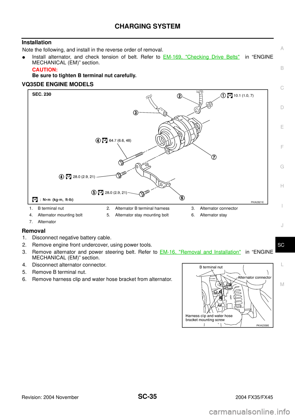
Installation
Note the following, and install in the reverse order of removal.
�Install alternator, and check tension of belt. Refer to EM-169, "Checking Drive Belts" in “ENGINE
MECHANICAL (EM)” section.
CAUTION:
Be sure to tighten B terminal nut carefully.
VQ35DE ENGINE MODELS
Removal
1. Disconnect negative battery cable.
2. Remove engine front undercover, using power tools.
3. Remove alternator and power steering belt. Refer to EM-16, "
Removal and Installation" in “ENGINE
MECHANICAL (EM)” section.
4. Disconnect alternator connector.
5. Remove B terminal nut.
6. Remove harness clip and water hose bracket from alternator.
1. B terminal nut 2. Alternator B terminal harness 3. Alternator connector
4. Alternator mounting bolt 5. Alternator stay mounting bolt 6. Alternator stay
7. Alternator
PKIA2821E
PKIA2358E
Page 4125 of 4449
SC-36
CHARGING SYSTEM
Revision: 2004 November 2004 FX35/FX45
7. Remove oil pressure switch harness clip from alternator stay.
(2WD)
8. Disconnect oil pressure switch connector. (2WD)
9. Remove alternator stay mounting bolts and alternator stay, using
power tools.
10. Remove alternator mounting bolt, using power tools.
11. Remove alternator assembly to the direction of under side the vehicle.
Installation
Note the following, and install in the reverse order of removal.
�Install alternator, and check tension of belt. Refer to EM-15, "Checking Drive Belts" in “ENGINE
MECHANICAL (EM)” section.
CAUTION:
Be sure to tighten B terminal nut carefully.
PKIA1923E
Page 4133 of 4449
SE-4
PREPARATION
Revision: 2004 November 2004 FX35/FX45
PREPARATIONPFP:00002
Special Service ToolsAIS002WV
The actual shapes of Kent-Moore tools may differ from those of special service tools illustrated here.
Commercial Service ToolsAIS002WW
Tool number
(Kent-Moore No.)
Tool nameDescription
(J-39570)
Chassis earLocating the noise
(J-43980)
NISSAN Squeak and Rattle
KitRepairing the cause of the noise
SIIA0993E
SIIA0994E
Tool nameDescription
Engine earLocating the noise
SIIA0995E

8. Disconnect oil pressure switch connector. (2WD)
9. Remove alterna")
