Page 3966 of 4449
. Refer to PS-41,
\"HYD")
POWER STEERING OIL PUMP
PS-33
C
D
E
F
H
I
J
K
L
MA
B
PS
Revision: 2004 November 2004 FX35/FX45
4. Remove piping of high pressure and low pressure (drain fluid from their pipings). Refer to PS-41,
"HYDRAULIC LINE" .
5. Remove mounting bolts, then remove power steering pump.
INSTALLATION
Refer to PS-41, "HYDRAULIC LINE" for tightening torque. Install in the reverse order removal.
�After installation, adjust belt tension. Refer to EM-15, "DRIVE BELTS" .
�After installation, bleed air. Refer to PS-8, "Air Bleeding Hydraulic System" .
Removal and Installation (VK45DE models)AGS000HJ
REMOVAL
1. Remove undercover from vehicle with power tool.
2. Remove power steering oil pump belt from auto tensioner. Refer to EM-169, "
DRIVE BELTS" .
3. Drain power steering fluid from reservoir tank.
4. Remove piping of high pressure and low pressure from power steering oil pump (drain fluid from their pip-
ings). Refer to PS-41, "
HYDRAULIC LINE" .
5. Remove mounting bolts, then remove power steering pump.
INSTALLATION
Refer to PS-41, "HYDRAULIC LINE" for tightening torque. Install in the reverse order removal.
After installation, bleed air. Refer to PS-8, "
Air Bleeding Hydraulic System" .
NOTE:
Adjustment of belt tension is no necessary because engine of this model equips auto tensioner.
Disassembly and Assembly (VQ35DE models)AGS000HE
INSPECTION BEFORE DISASSEMBLY
Disassemble power steering oil pump only if the following items are found.
�Oil leakage from oil pump
�Deformed or damaged pulley
1. Rear cover 2. Teflon ring 3. O-ring
4. Rear side plate 5. Rotor snap ring 6. Dowel pin
7. Cam ring 8. Rotor 9. Vane
10. Cartridge 11. Front side plate 12. O-ring
13. Flow control valve A 14. Spring 15. Flow control valve B assembly
16. Body assembly 17. Oil seal 18. Pulley
19. O-ring 20. Suction pipe 21. Bracket
SGIA0622E
Page 3967 of 4449

PS-34
POWER STEERING OIL PUMP
Revision: 2004 November 2004 FX35/FX45
�Poor performance
DISASSEMBLY
NOTE:
Fix oil pump in vise as the occasion demands.
CAUTION:
When retaining drive shaft in a vise, always use copper or aluminum plates between vise and shaft.
1. Unscrew four rear cover bolts and remove rear cover from body assembly.
2. Remove rear side plate from cartridge, then remove Teflon ring and O-ring from rear side plate.
3. Remove rotor snap ring with snap ring pliers, and remove pulley
from body assembly.
CAUTION:
When removing rotor snap ring, be careful not to damage
pulley shaft.
4. Remove oil seal from body assembly.
5. Remove cam ring, rotor, vane, front side plate, flow control valve
A, spring, flow control valve B assembly and O-ring from body
assembly.
CAUTION:
Be careful not to drop and deform flow control valve A and
flow control valve B assembly.
6. Remove suction pipe from body assembly.
7. Remove O-ring from suction pipe.
8. Remove bracket from body assembly.
INSPECTION AFTER DISASSEMBLY
Body Assembly and Rear Cover Inspection
Check body assembly and the inside of rear cover for damage. If any damage is found, replace with new part
for rear cover, and replace with new power steering pump assembly for body assembly.
Cartridge Assembly Inspection
Check cam ring, side plate, rotor and vane for damage. If any damage is found, replace cartridge assembly
with new one.
ASSEMBLY
NOTE:
Fix oil pump in vise as occasion demands.
CAUTION:
When retaining drive shaft in a vise, always use copper or aluminum plates between vise and shaft.
1. Apply Genuine Nissan PSF or equivalent to oil seal lip and to the
circumference of oil seal. Using a drift (SST), install oil seal to
body assembly.
NOTE:
Do not reuse oil seal.
2. If dowel pin has been removed, insert it into body assembly by
hand. If it cannot be inserted by hand, lightly tap with a hammer.
SGIA0059E
SGIA0526E
SGIA0527E
Page 3968 of 4449
POWER STEERING OIL PUMP
PS-35
C
D
E
F
H
I
J
K
L
MA
B
PS
Revision: 2004 November 2004 FX35/FX45
3. Install flow control valve A, flow control valve spring and flow
control valve B assembly to locations shown in the figure.
4. Match dowel pin A on flow control valve A, shown in the figure,
with cutout B of front side plate and then install front side plate to
body assembly.
5. Install cam ring onto front side plate with smaller slit of cam ring
facing body assembly.
6. Install pulley to body assembly.
CAUTION:
When installing pulley, be careful not to scratch oil seal.
7. Face the side of rotor with punch mark towards rear cover, and
attach rotor to pulley shaft.
SGIA0526E
SGIA0528E
SGIA0623E
SGIA0529E
Page 3969 of 4449
 box, install rotor snap
rin")
PS-36
POWER STEERING OIL PUMP
Revision: 2004 November 2004 FX35/FX45
8. Install vane to rotor with facing the round portion outside.
9. Using a hammer and a 10 mm (0.39 in) box, install rotor snap
ring to slot in pulley shaft.
NOTE:
Do not reuse snap ring.
CAUTION:
Be careful not to damage rotor and pulley shaft.
10. Match dowel pin A on flow control valve A, shown in the figure,
with cutout B of rear side plate and install rear side plate to car-
tridge.
11. Apply Genuine Nissan PSF or equivalent to O-ring and install O-
ring into rear side plate.
NOTE:
Do not reuse O-ring.
12. Apply Genuine Nissan PSF or equivalent to Teflon ring and
Install Teflon ring into rear side plate.
NOTE:
Do not reuse Teflon ring.
13. Position rear cover on body assembly and tighten mounting bolts to specified torque.
14. Apply Genuine Nissan PSF or equivalent to O-ring and install O-ring into suction pipe.
NOTE:
Do not reuse O-ring.
15. Install suction pipe into body assembly.
16. Install bracket to body assembly and tighten mounting bolts to specified torque.
SST843A
SGIA0063E
SGIA0530E
Page 3970 of 4449
AGS000H4
INSPECTION BEFORE DISASSEMBLY
Disassemble power steering")
POWER STEERING OIL PUMP
PS-37
C
D
E
F
H
I
J
K
L
MA
B
PS
Revision: 2004 November 2004 FX35/FX45
Disassembly and Assembly (VK45DE models)AGS000H4
INSPECTION BEFORE DISASSEMBLY
Disassemble power steering oil pump only if the following items are found.
�Oil leakage from oil pump.
�Deformed or damaged pulley
�Poor performance
DISASSEMBLY
NOTE:
Fix oil pump in vise as the occasion demands.
CAUTION:
When retaining drive shaft in a vise, always use copper or aluminum plates between vise and shaft.
1. Unscrew three bracket bolts and remove bracket from rear cover.
2. Unscrew four rear cover bolts and remove rear cover from body assembly.
3. Remove gasket from body assembly.
4. Remove lock pin, cartridge and side plate from body assembly.
5. Remove pulley from drive shaft assembly.
1. Bracket 2. Rear cover 3. Gasket
4. Lock pin 5. Cam ring 6. Rotor
7. Vane 8. Cartridge 9. Side plate
10. O-ring 11. Body assembly 12. Oil seal
13. Drive shaft assembly 14. Snap ring 15. Pulley
16. Spring washer 17. Spring 18. Flow control valve
19. O-ring 20. Connector bolt 21. Joint
22. Washer 23. Suction pipe 24. O-ring
SGIA0523E
Page 3971 of 4449

PS-38
POWER STEERING OIL PUMP
Revision: 2004 November 2004 FX35/FX45
6. Remove snap ring from drive shaft assembly and press out it.
CAUTION:
When removing snap ring, be careful not to damage drive
shaft assembly.
7. Using a screwdriver, remove oil seal for body assembly.
8. Remove O-ring from body assembly.
9. Loosen lock nut and remove washer, O-ring, joint then remove
connector bolt, O-ring and pull out flow control valve and spring
from body assembly.
CAUTION:
Be careful not to drop and deform the flow control valve.
10. Remove suction pipe from body assembly.
11. Remove O-ring for suction pipe.
INSPECTION AFTER DISASSEMBLY
Body Assembly and Rear Cover Inspection
Check body assembly and the inside of rear cover for damage. If any damage is found, replace with new part
for rear cover and replace with new power steering pump assembly for body assembly.
Cartridge Assembly Inspection
Check cam ring, side plate, rotor and vane for damage. If any damage is found, replace cartridge assembly
with new one.
ASSEMBLY
NOTE:
Fix oil pump in vise as vise occasion demands.
CAUTION:
When retaining drive shaft assembly in a vise, always use copper or aluminum plates between vise
and shaft.
SST010B
SST034A
SGIA0524E
Page 3973 of 4449
PS-40
POWER STEERING OIL PUMP
Revision: 2004 November 2004 FX35/FX45
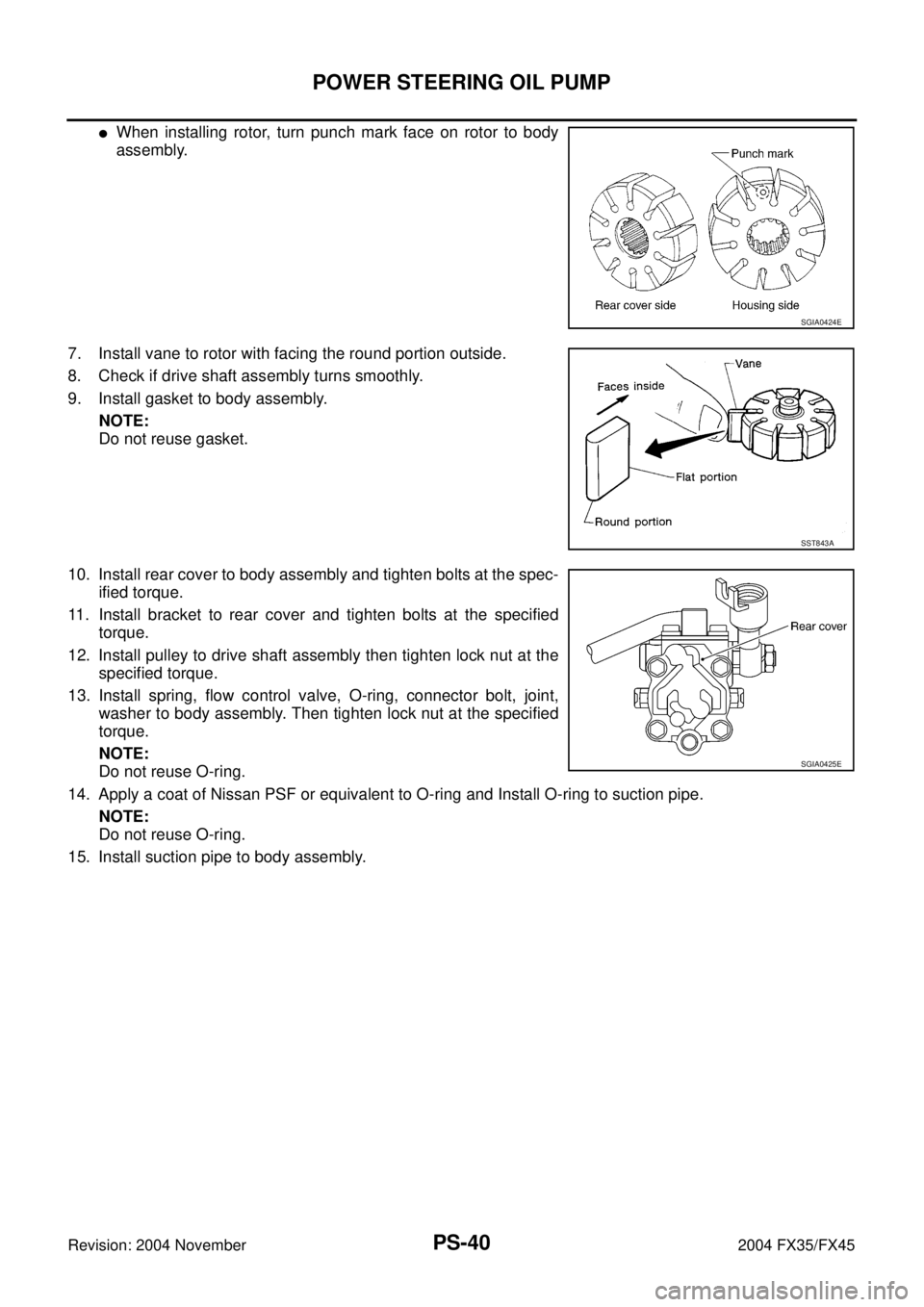
�When installing rotor, turn punch mark face on rotor to body
assembly.
7. Install vane to rotor with facing the round portion outside.
8. Check if drive shaft assembly turns smoothly.
9. Install gasket to body assembly.
NOTE:
Do not reuse gasket.
10. Install rear cover to body assembly and tighten bolts at the spec-
ified torque.
11. Install bracket to rear cover and tighten bolts at the specified
torque.
12. Install pulley to drive shaft assembly then tighten lock nut at the
specified torque.
13. Install spring, flow control valve, O-ring, connector bolt, joint,
washer to body assembly. Then tighten lock nut at the specified
torque.
NOTE:
Do not reuse O-ring.
14. Apply a coat of Nissan PSF or equivalent to O-ring and Install O-ring to suction pipe.
NOTE:
Do not reuse O-ring.
15. Install suction pipe to body assembly.
SGIA0424E
SST843A
SGIA0425E
Page 3986 of 4449
")
WHEEL HUB
RAX-5
C
E
F
G
H
I
J
K
L
MA
B
RAX
Revision: 2004 November 2004 FX35/FX45
WHEEL HUBPFP:43202
On-Vehicle Inspection and ServiceADS000C4
Make sure the mounting conditions (looseness, back lash) of each component and component status (wear,
damage) are normal.
WHEEL BEARING INSPECTION
�Move wheel hub in the axial direction by hand. Make sure there is no looseness of wheel bearing.
�Rotate wheel hub and make sure there is no unusual noise or other irregular conditions. If there are any
irregular conditions, replace wheel bearings.
Removal and InstallationADS000C5
REMOVAL
1. Remove tire with power tool.
2. Remove brake caliper with power tool. Hang it in a place where it will not interfere with work. Refer to BR-
26, "Removal and Installation of Brake Caliper Assembly" .
NOTE:
�Avoid depressing brake pedal while brake caliper is removed.
3. Remove disc rotor.
4. Remove wheel sensor from axle. Refer to BRC-57, "
WHEEL SENSORS" .
CAUTION:
Do not pull on wheel sensor harness.
5. Remove cotter pin. Then remove lock nut from drive shaft.
6. Separate drive shaft from wheel hub and bearing assembly by lightly tapping the end with a suitable ham-
mer and wood block. If it is hard to separate, use a suitable puller.
7. Remove fixing bolts of wheel hub and bearing assembly with power tool, then remove wheel hub and
bearing assembly from axle.
8. Remove parking brake cable and parking brake shoe from back plate. Refer to PB-5, "
PARKING BRAKE
SHOE" and PB-3, "PARKING BRAKE CONTROL" .
9. Remove fixing nuts of anchor block with power tool, then remove anchor block and back plate from axle.Axial end play : 0 mm (0 in)
1. Drive shaft 2. Bushing 3. Axle
4. Back plate 5. Anchor block 6. Wheel bearing
7. Wheel hub 8. Cotter pin
SDIA1481E