Page 3108 of 4449
PRECAUTIONS
GI-5
C
D
E
F
G
H
I
J
K
L
MB
GI
Revision: 2004 November 2004 FX35/FX45
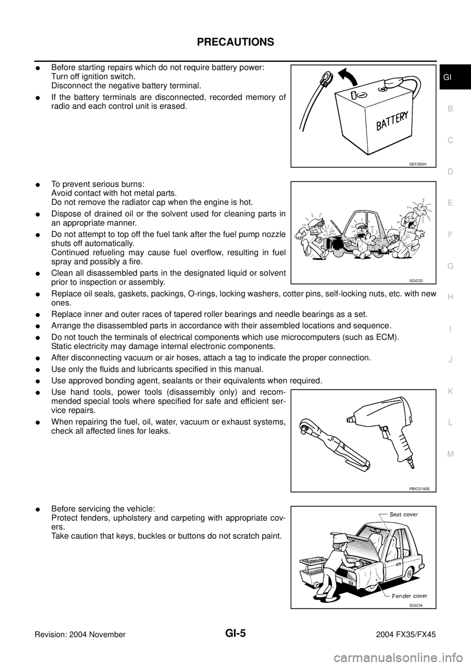
�Before starting repairs which do not require battery power:
Turn off ignition switch.
Disconnect the negative battery terminal.
�If the battery terminals are disconnected, recorded memory of
radio and each control unit is erased.
�To prevent serious burns:
Avoid contact with hot metal parts.
Do not remove the radiator cap when the engine is hot.
�Dispose of drained oil or the solvent used for cleaning parts in
an appropriate manner.
�Do not attempt to top off the fuel tank after the fuel pump nozzle
shuts off automatically.
Continued refueling may cause fuel overflow, resulting in fuel
spray and possibly a fire.
�Clean all disassembled parts in the designated liquid or solvent
prior to inspection or assembly.
�Replace oil seals, gaskets, packings, O-rings, locking washers, cotter pins, self-locking nuts, etc. with new
ones.
�Replace inner and outer races of tapered roller bearings and needle bearings as a set.
�Arrange the disassembled parts in accordance with their assembled locations and sequence.
�Do not touch the terminals of electrical components which use microcomputers (such as ECM).
Static electricity may damage internal electronic components.
�After disconnecting vacuum or air hoses, attach a tag to indicate the proper connection.
�Use only the fluids and lubricants specified in this manual.
�Use approved bonding agent, sealants or their equivalents when required.
�Use hand tools, power tools (disassembly only) and recom-
mended special tools where specified for safe and efficient ser-
vice repairs.
�When repairing the fuel, oil, water, vacuum or exhaust systems,
check all affected lines for leaks.
�Before servicing the vehicle:
Protect fenders, upholstery and carpeting with appropriate cov-
ers.
Take caution that keys, buckles or buttons do not scratch paint.
SEF289H
SGI233
PBIC0190E
SGI234
Page 3114 of 4449
HOW TO USE THIS MANUAL
GI-11
C
D
E
F
G
H
I
J
K
L
MB
GI
Revision: 2004 November 2004 FX35/FX45
How to Follow Trouble DiagnosesAAS000E1
DESCRIPTION
NOTICE:
Trouble diagnoses indicate work procedures required to diagnose problems effectively. Observe the following
instructions before diagnosing.
1.Before performing trouble diagnoses, read the “Preliminary Check”, the “Symptom Chart” or the
“Work Flow”.
2.After repairs, re-check that the problem has been completely eliminated.
3.Refer to Component Parts and Harness Connector Location for the Systems described in each
section for identification/location of components and harness connectors.
4.Refer to the Circuit Diagram for quick pinpoint check.
If you need to check circuit continuity between harness connectors in more detail, such as when a
sub-harness is used, refer to Wiring Diagram in each individual section and Harness Layout in PG
section for identification of harness connectors.
5.When checking circuit continuity, ignition switch should be OFF.
6.Before checking voltage at connectors, check battery voltage.
7.After accomplishing the Diagnostic Procedures and Electrical Components Inspection, make sure
that all harness connectors are reconnected as they were.
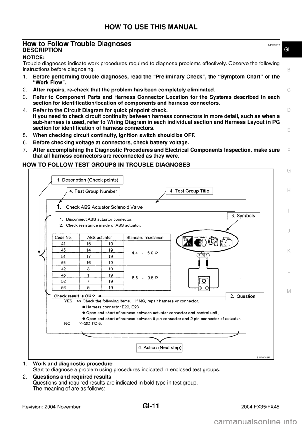
HOW TO FOLLOW TEST GROUPS IN TROUBLE DIAGNOSES
1.Work and diagnostic procedure
Start to diagnose a problem using procedures indicated in enclosed test groups.
2.Questions and required results
Questions and required results are indicated in bold type in test group.
The meaning of are as follows:
SAIA0256E
Page 3117 of 4449
GI-14
HOW TO USE THIS MANUAL
Revision: 2004 November 2004 FX35/FX45
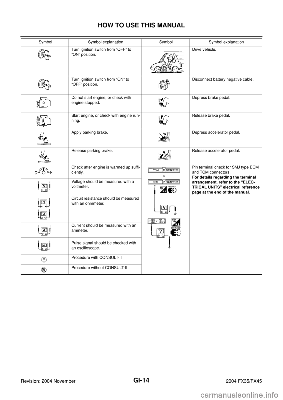
Turn ignition switch from “OFF” to
“ON” position.Drive vehicle.
Turn ignition switch from “ON” to
“OFF” position.Disconnect battery negative cable.
Do not start engine, or check with
engine stopped.Depress brake pedal.
Start engine, or check with engine run-
ning.Release brake pedal.
Apply parking brake. Depress accelerator pedal.
Release parking brake. Release accelerator pedal.
Check after engine is warmed up suffi-
ciently.Pin terminal check for SMJ type ECM
and TCM connectors.
For details regarding the terminal
arrangement, refer to the “ELEC-
TRICAL UNITS” electrical reference
page at the end of the manual. Voltage should be measured with a
voltmeter.
Circuit resistance should be measured
with an ohmmeter.
Current should be measured with an
ammeter.
Pulse signal should be checked with
an oscilloscope.
Procedure with CONSULT-II
Procedure without CONSULT-II Symbol Symbol explanation Symbol Symbol explanation
Page 3125 of 4449
GI-22
HOW TO USE THIS MANUAL
Revision: 2004 November 2004 FX35/FX45
Reference Area
The Reference Area of the wiring diagram contains references to additional electrical reference pages at the
end of the manual. If connector numbers and titles are shown in the Reference Area of the wiring diagram,
these connector symbols are not shown in the Connector Area.
SGI092A
Page 3127 of 4449
GI-24
SERVICE INFORMATION FOR ELECTRICAL INCIDENT
Revision: 2004 November 2004 FX35/FX45
SERVICE INFORMATION FOR ELECTRICAL INCIDENTPFP:00000
How to Check Terminal AAS000E4
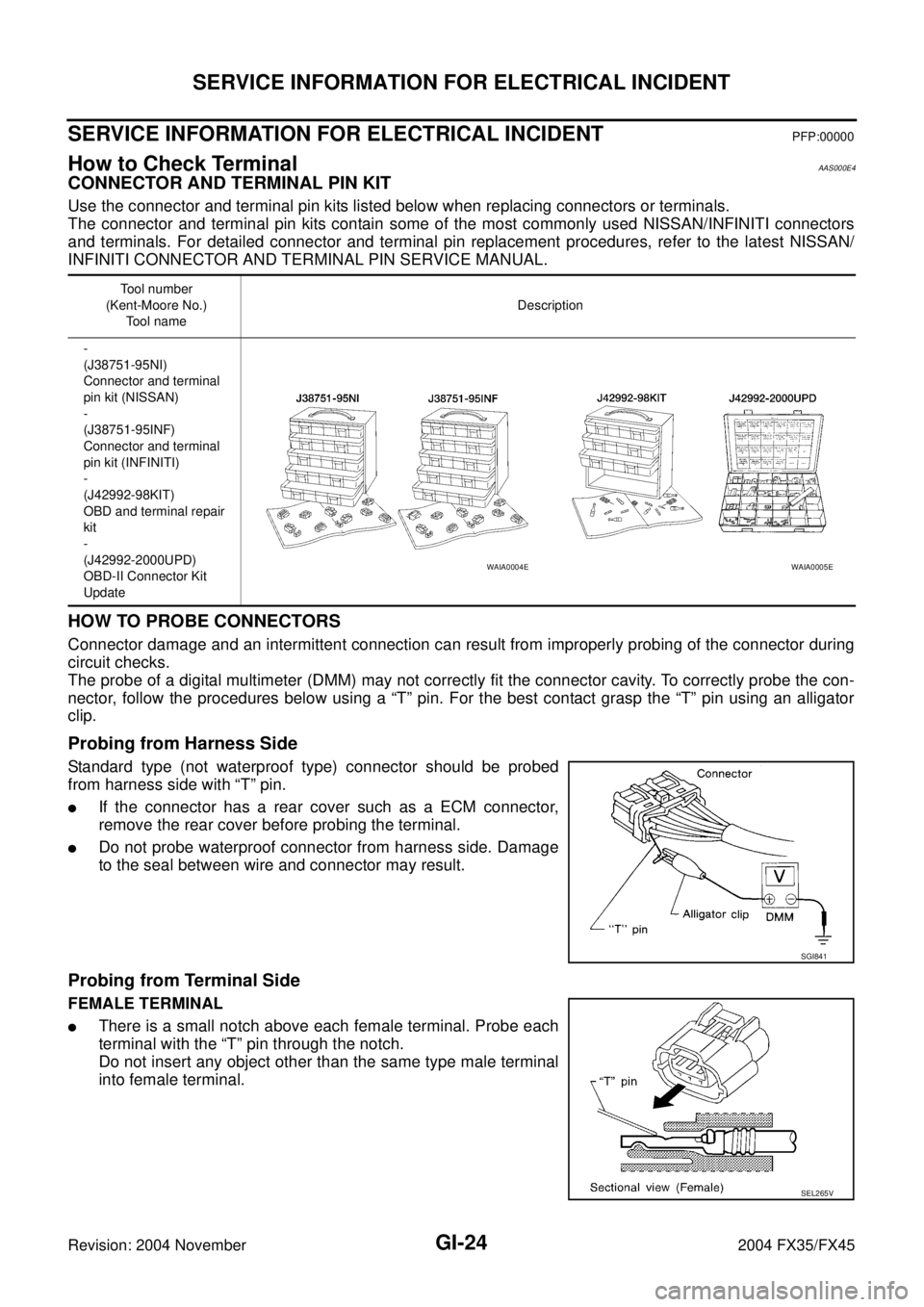
CONNECTOR AND TERMINAL PIN KIT
Use the connector and terminal pin kits listed below when replacing connectors or terminals.
The connector and terminal pin kits contain some of the most commonly used NISSAN/INFINITI connectors
and terminals. For detailed connector and terminal pin replacement procedures, refer to the latest NISSAN/
INFINITI CONNECTOR AND TERMINAL PIN SERVICE MANUAL.
HOW TO PROBE CONNECTORS
Connector damage and an intermittent connection can result from improperly probing of the connector during
circuit checks.
The probe of a digital multimeter (DMM) may not correctly fit the connector cavity. To correctly probe the con-
nector, follow the procedures below using a “T” pin. For the best contact grasp the “T” pin using an alligator
clip.
Probing from Harness Side
Standard type (not waterproof type) connector should be probed
from harness side with “T” pin.
�If the connector has a rear cover such as a ECM connector,
remove the rear cover before probing the terminal.
�Do not probe waterproof connector from harness side. Damage
to the seal between wire and connector may result.
Probing from Terminal Side
FEMALE TERMINAL
�There is a small notch above each female terminal. Probe each
terminal with the “T” pin through the notch.
Do not insert any object other than the same type male terminal
into female terminal.
Tool number
(Kent-Moore No.)
Tool nameDescription
-
(J38751-95NI)
Connector and terminal
pin kit (NISSAN)
-
(J38751-95INF)
Connector and terminal
pin kit (INFINITI)
-
(J42992-98KIT)
OBD and terminal repair
kit
-
(J42992-2000UPD)
OBD-II Connector Kit
Update
WAIA0004EWAIA0005E
SGI841
SEL265V
Page 3128 of 4449
SERVICE INFORMATION FOR ELECTRICAL INCIDENT
GI-25
C
D
E
F
G
H
I
J
K
L
MB
GI
Revision: 2004 November 2004 FX35/FX45
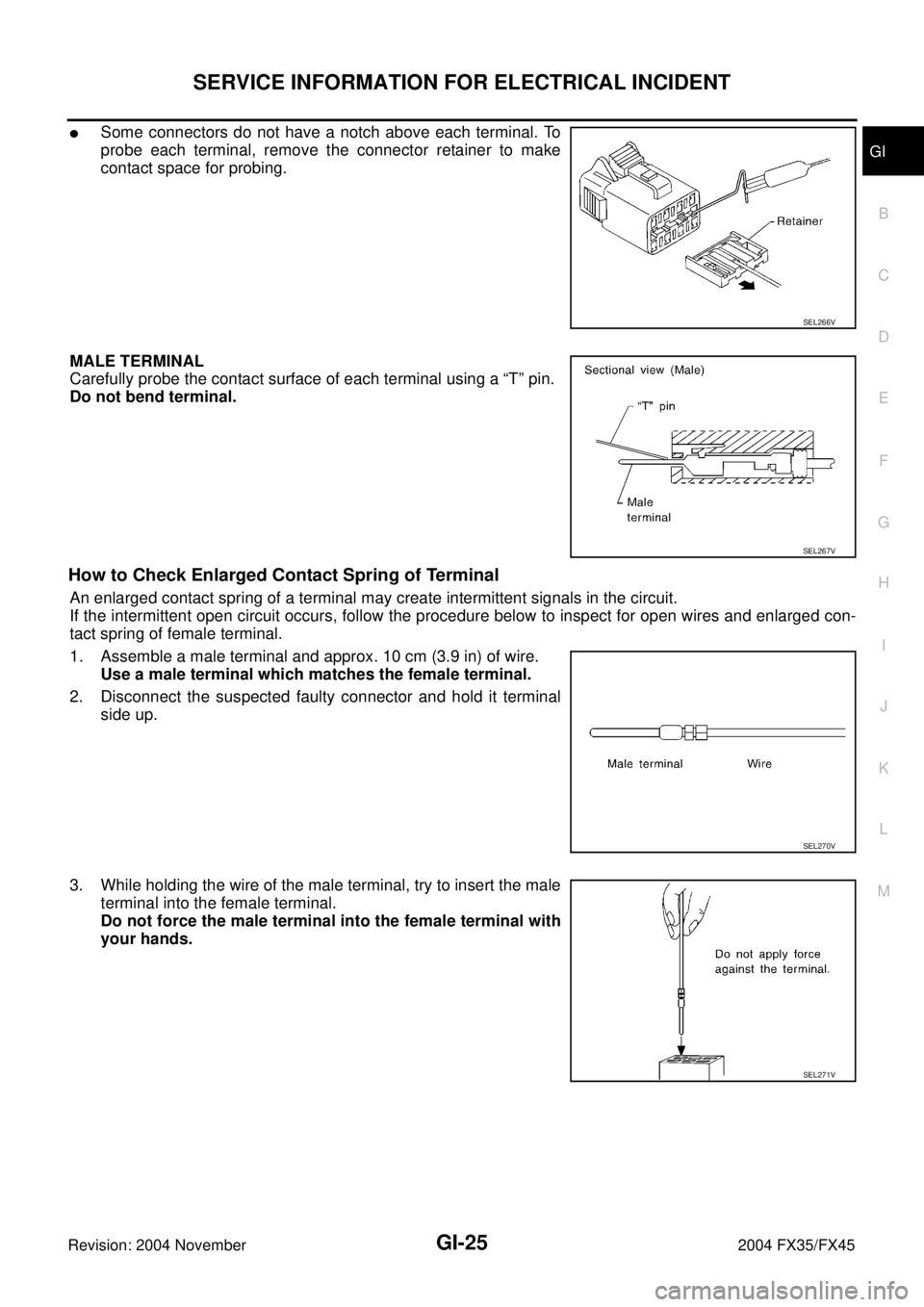
�Some connectors do not have a notch above each terminal. To
probe each terminal, remove the connector retainer to make
contact space for probing.
MALE TERMINAL
Carefully probe the contact surface of each terminal using a “T” pin.
Do not bend terminal.
How to Check Enlarged Contact Spring of Terminal
An enlarged contact spring of a terminal may create intermittent signals in the circuit.
If the intermittent open circuit occurs, follow the procedure below to inspect for open wires and enlarged con-
tact spring of female terminal.
1. Assemble a male terminal and approx. 10 cm (3.9 in) of wire.
Use a male terminal which matches the female terminal.
2. Disconnect the suspected faulty connector and hold it terminal
side up.
3. While holding the wire of the male terminal, try to insert the male
terminal into the female terminal.
Do not force the male terminal into the female terminal with
your hands.
SEL266V
SEL267V
SEL270V
SEL271V
Page 3129 of 4449
GI-26
SERVICE INFORMATION FOR ELECTRICAL INCIDENT
Revision: 2004 November 2004 FX35/FX45
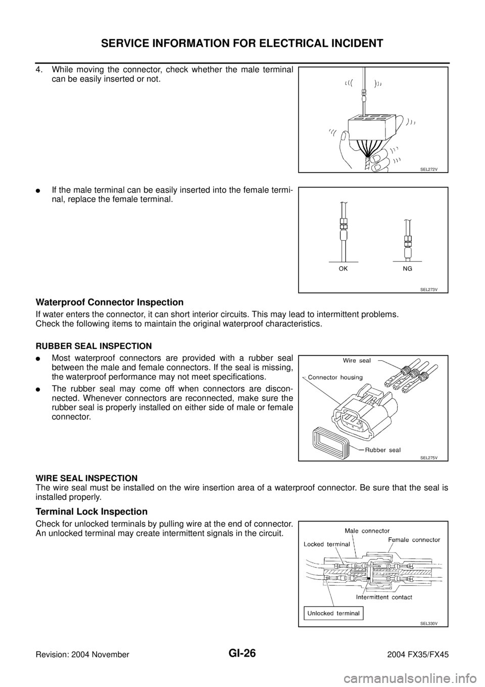
4. While moving the connector, check whether the male terminal
can be easily inserted or not.
�If the male terminal can be easily inserted into the female termi-
nal, replace the female terminal.
Waterproof Connector Inspection
If water enters the connector, it can short interior circuits. This may lead to intermittent problems.
Check the following items to maintain the original waterproof characteristics.
RUBBER SEAL INSPECTION
�Most waterproof connectors are provided with a rubber seal
between the male and female connectors. If the seal is missing,
the waterproof performance may not meet specifications.
�The rubber seal may come off when connectors are discon-
nected. Whenever connectors are reconnected, make sure the
rubber seal is properly installed on either side of male or female
connector.
WIRE SEAL INSPECTION
The wire seal must be installed on the wire insertion area of a waterproof connector. Be sure that the seal is
installed properly.
Terminal Lock Inspection
Check for unlocked terminals by pulling wire at the end of connector.
An unlocked terminal may create intermittent signals in the circuit.
SEL272V
SEL273V
SEL275V
SEL330V
Page 3130 of 4449
SERVICE INFORMATION FOR ELECTRICAL INCIDENT
GI-27
C
D
E
F
G
H
I
J
K
L
MB
GI
Revision: 2004 November 2004 FX35/FX45
How to Perform Efficient Diagnosis for an Electrical IncidentAAS000E5
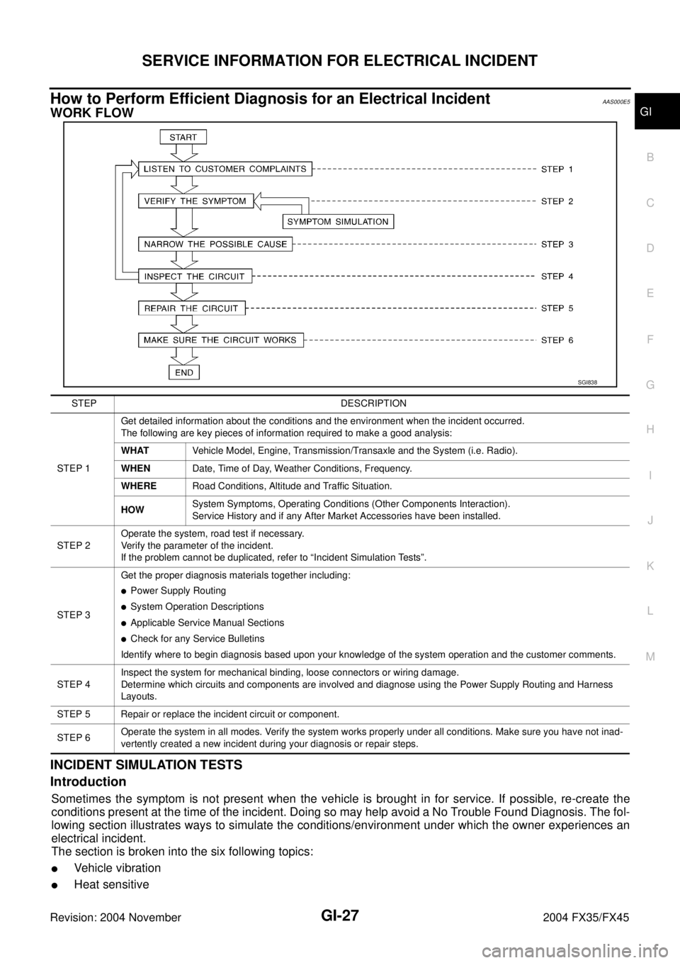
WORK FLOW
INCIDENT SIMULATION TESTS
Introduction
Sometimes the symptom is not present when the vehicle is brought in for service. If possible, re-create the
conditions present at the time of the incident. Doing so may help avoid a No Trouble Found Diagnosis. The fol-
lowing section illustrates ways to simulate the conditions/environment under which the owner experiences an
electrical incident.
The section is broken into the six following topics:
�Vehicle vibration
�Heat sensitive
SGI838
STEP DESCRIPTION
STEP 1Get detailed information about the conditions and the environment when the incident occurred.
The following are key pieces of information required to make a good analysis:
WHATVehicle Model, Engine, Transmission/Transaxle and the System (i.e. Radio).
WHENDate, Time of Day, Weather Conditions, Frequency.
WHERERoad Conditions, Altitude and Traffic Situation.
HOWSystem Symptoms, Operating Conditions (Other Components Interaction).
Service History and if any After Market Accessories have been installed.
STEP 2Operate the system, road test if necessary.
Verify the parameter of the incident.
If the problem cannot be duplicated, refer to “Incident Simulation Tests”.
STEP 3Get the proper diagnosis materials together including:
�Power Supply Routing
�System Operation Descriptions
�Applicable Service Manual Sections
�Check for any Service Bulletins
Identify where to begin diagnosis based upon your knowledge of the system operation and the customer comments.
STEP 4Inspect the system for mechanical binding, loose connectors or wiring damage.
Determine which circuits and components are involved and diagnose using the Power Supply Routing and Harness
Layouts.
STEP 5 Repair or replace the incident circuit or component.
STEP 6Operate the system in all modes. Verify the system works properly under all conditions. Make sure you have not inad-
vertently created a new incident during your diagnosis or repair steps.