Page 272 of 4449

TROUBLE DIAGNOSIS FOR SYMPTOMS
AT-195
D
E
F
G
H
I
J
K
L
MA
B
AT
Revision: 2004 November 2004 FX35/FX45
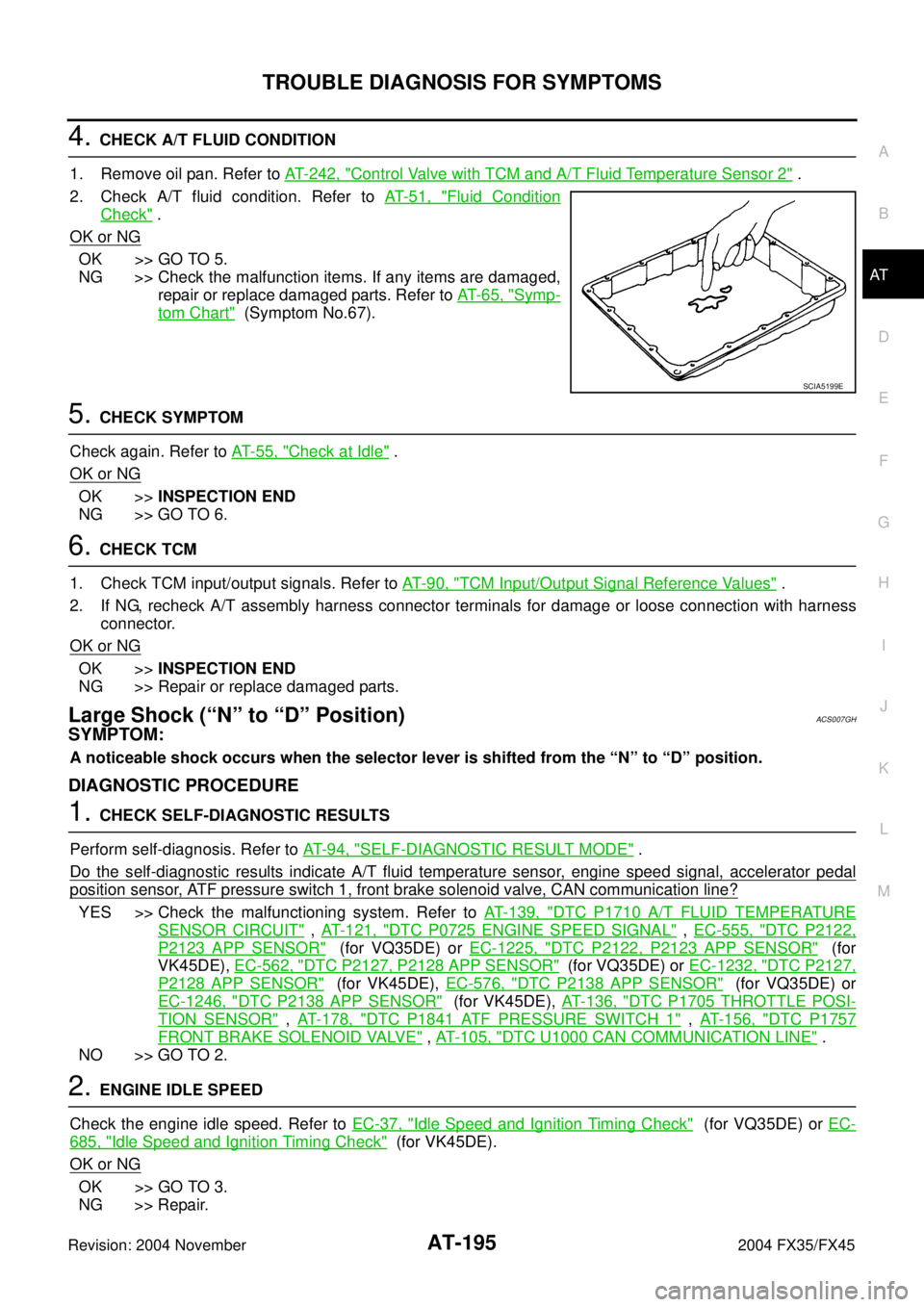
4. CHECK A/T FLUID CONDITION
1. Remove oil pan. Refer to AT- 2 4 2 , "
Control Valve with TCM and A/T Fluid Temperature Sensor 2" .
2. Check A/T fluid condition. Refer to AT- 5 1 , "
Fluid Condition
Check" .
OK or NG
OK >> GO TO 5.
NG >> Check the malfunction items. If any items are damaged,
repair or replace damaged parts. Refer to AT- 6 5 , "
Symp-
tom Chart" (Symptom No.67).
5. CHECK SYMPTOM
Check again. Refer to AT- 5 5 , "
Check at Idle" .
OK or NG
OK >>INSPECTION END
NG >> GO TO 6.
6. CHECK TCM
1. Check TCM input/output signals. Refer to AT- 9 0 , "
TCM Input/Output Signal Reference Values" .
2. If NG, recheck A/T assembly harness connector terminals for damage or loose connection with harness
connector.
OK or NG
OK >>INSPECTION END
NG >> Repair or replace damaged parts.
Large Shock (“N” to “D” Position)ACS007GH
SYMPTOM:
A noticeable shock occurs when the selector lever is shifted from the “N” to “D” position.
DIAGNOSTIC PROCEDURE
1. CHECK SELF-DIAGNOSTIC RESULTS
Perform self-diagnosis. Refer to AT- 9 4 , "
SELF-DIAGNOSTIC RESULT MODE" .
Do the self-diagnostic results indicate A/T fluid temperature sensor, engine speed signal, accelerator pedal
position sensor, ATF pressure switch 1, front brake solenoid valve, CAN communication line?
YES >> Check the malfunctioning system. Refer to AT- 1 3 9 , "DTC P1710 A/T FLUID TEMPERATURE
SENSOR CIRCUIT" , AT- 1 2 1 , "DTC P0725 ENGINE SPEED SIGNAL" , EC-555, "DTC P2122,
P2123 APP SENSOR" (for VQ35DE) or EC-1225, "DTC P2122, P2123 APP SENSOR" (for
VK45DE), EC-562, "
DTC P2127, P2128 APP SENSOR" (for VQ35DE) or EC-1232, "DTC P2127,
P2128 APP SENSOR" (for VK45DE), EC-576, "DTC P2138 APP SENSOR" (for VQ35DE) or
EC-1246, "
DTC P2138 APP SENSOR" (for VK45DE), AT- 1 3 6 , "DTC P1705 THROTTLE POSI-
TION SENSOR" , AT- 1 7 8 , "DTC P1841 ATF PRESSURE SWITCH 1" , AT- 1 5 6 , "DTC P1757
FRONT BRAKE SOLENOID VALVE" , AT- 1 0 5 , "DTC U1000 CAN COMMUNICATION LINE" .
NO >> GO TO 2.
2. ENGINE IDLE SPEED
Check the engine idle speed. Refer to EC-37, "
Idle Speed and Ignition Timing Check" (for VQ35DE) or EC-
685, "Idle Speed and Ignition Timing Check" (for VK45DE).
OK or NG
OK >> GO TO 3.
NG >> Repair.
SCIA5199E
Page 311 of 4449

AT-234
SHIFT CONTROL SYSTEM
Revision: 2004 November 2004 FX35/FX45
REMOVAL
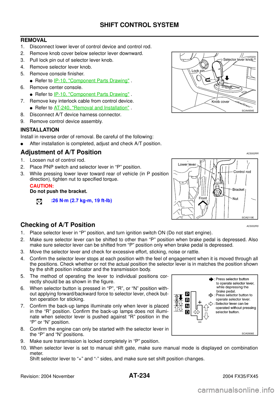
1. Disconnect lower lever of control device and control rod.
2. Remove knob cover below selector lever downward.
3. Pull lock pin out of selector lever knob.
4. Remove selector lever knob.
5. Remove console finisher.
�Refer to IP-10, "Component Parts Drawing" .
6. Remove center console.
�Refer to IP-10, "Component Parts Drawing" .
7. Remove key interlock cable from control device.
�Refer to AT- 2 4 0 , "Removal and Installation" .
8. Disconnect A/T device harness connector.
9. Remove control device assembly.
INSTALLATION
Install in reverse order of removal. Be careful of the following:
�After installation is completed, adjust and check A/T position.
Adjustment of A/T PositionACS002RR
1. Loosen nut of control rod.
2. Place PNP switch and selector lever in “P” position.
3. While pressing lower lever toward rear of vehicle (in P position
direction), tighten nut to specified torque.
CAUTION:
Do not push the bracket.
Checking of A/T PositionACS002RS
1. Place selector lever in “P” position, and turn ignition switch ON (Do not start engine).
2. Make sure selector lever can be shifted to other than “P” position when brake pedal is depressed. Also
make sure selector lever can be shifted from “P” position only when brake pedal is depressed.
3. Move the selector lever and check for excessive effort, sticking, noise or rattle.
4. Confirm the selector lever stops at each position with the feel of engagement when it is moved through all
the positions. Check whether or not the actual position the selector lever is in matches the position shown
by the shift position indicator and the transmission body.
5. The method of operating the lever to individual positions cor-
rectly should be as shown in the figure.
6. When selector button is pressed in “P”, “R”, or “N” position with-
out applying forward/backward force to selector lever, check but-
ton operation for sticking.
7. Confirm the back-up lamps illuminate only when lever is placed
in the “R” position. Confirm the back-up lamps does not illumi-
nate when selector lever is pushed against “R” position in the
“P” or “N” position.
8. Confirm the engine can only be started with the selector lever in
the “P” and “N” positions.
9. Make sure transmission is locked completely in “P” position.
10. When selector lever is set to manual shift gate, make sure manual mode is displayed on combination
meter.
Shift selector lever to “+” and “-” sides, and make sure set shift position changes.
SCIA4954E
:26 N·m (2.7 kg-m, 19 ft-lb)
SCIA2119E
SCIA3906E
Page 312 of 4449
A/T SHIFT LOCK SYSTEM
AT-235
D
E
F
G
H
I
J
K
L
MA
B
AT
Revision: 2004 November 2004 FX35/FX45
A/T SHIFT LOCK SYSTEMPFP:34950
DescriptionACS002RT
�The mechanical key interlock mechanism also operates as a shift lock:
With the ignition switch turned to ON, the selector lever cannot be shifted from “P” position to any other
position unless the brake pedal is depressed.
With the key removed, the selector lever cannot be shifted from “P” position to any other position.
The key cannot be removed unless the selector lever is placed in “P” position.
�The shift lock and key interlock mechanisms are controlled by the ON-OFF operation of the shift lock sole-
noid and by the operation of the rotator and slider located inside the key cylinder.
Shift Lock System Electrical Parts LocationACS002RU
SCIA2149E
Page 314 of 4449

A/T SHIFT LOCK SYSTEM
AT-237
D
E
F
G
H
I
J
K
L
MA
B
AT
Revision: 2004 November 2004 FX35/FX45
Diagnostic ProcedureACS002RW
SYMPTOM 1:
�Selector lever cannot be moved from “P” position with key in ON position and brake pedal
applied.
�Selector lever can be moved from “P” position with key in ON position and brake pedal released.
�Selector lever can be moved from “P” position when key is removed from key cylinder.
SYMPTOM 2:
�Ignition key cannot be removed when selector lever is set to “P” position.
�Ignition key can be removed when selector lever is set to any position except “P” position.
1. CHECK KEY INTERLOCK CABLE
Check the key interlock cable for damage.
OK or NG
OK >> GO TO 2.
NG >> Repair key interlock cable. Refer to AT- 2 3 9 , "
KEY INTERLOCK CABLE" .
2. CHECK SELECTOR LEVER POSITION
Check the selector lever position for damage.
OK or NG
OK >> GO TO 3.
NG >> Adjustment control linkage. Refer to AT- 2 3 4 , "
Adjustment of A/T Position" .
3. CHECK SHIFT LOCK SOLENOID AND PARK POSITION SWITCH
1. Connect A/T device harness connector.
2. Turn ignition switch “ON”.
3. Selector lever is set in “P” position.
4. Check operation sound.
OK or NG
OK >>INSPECTION END
NG >> GO TO 4.
4. CHECK POWER SOURCE
1. Turn ignition switch “ON”. (Do not start engine.)
2. Check the voltage between A/T device harness connector M67
terminal 1(G/R) and ground. Refer to AT- 2 3 6 , "
Wiring Diagram
— AT — SHIFT" .
OK or NG
OK >> GO TO 7.
NG >> GO TO 5.
Condition Brake pedal Operation sound
When ignition switch is turned to
“ON” position and selector lever
is set in “P” position.Depressed Yes
Released No
Condition Brake pedal Data (Approx.)
When ignition switch is turned to
“ON” position.Depressed Battery voltage
Released 0V
SCIA2122E
Page 315 of 4449

AT-238
A/T SHIFT LOCK SYSTEM
Revision: 2004 November 2004 FX35/FX45
5. CHECK STOP LAMP SWITCH
1. Turn ignition switch “OFF”.
2. Disconnect stop lamp switch harness connector.
3. Check continuity between stop lamp switch harness connector
E210 terminals 3(G) and 4(OR). Refer to AT- 2 3 6 , "
Wiring Dia-
gram — AT — SHIFT" .
Check stop lamp switch after adjusting brake pedal — refer to
BR-6, "
BRAKE PEDAL" .
OK or NG
OK >> GO TO 6.
NG >> Repair or replace damaged parts.
6. DETECT MALFUNCTIONING ITEM
Check the following items. If any items are damaged, repair or replace damaged parts.
�Harness for short or open between ignition switch and stop lamp switch harness terminal 3(G).
�Harness for short or open between stop lamp switch harness terminal 4(O/R) and A/T device harness ter-
minal 1(G/R).
�10A fuse [No.12, located in the fuse block (J/B)].
�Ignition switch. Refer to PG-3, "POWER SUPPLY ROUTING CIRCUIT" .
OK or NG
OK >>INSPECTION END
NG >> Repair or replace damaged parts.
7. CHECK GROUND CIRCUIT
1. Turn ignition switch “OFF”.
2. Disconnect A/T device harness connector.
3. Check continuity between A/T device harness connector M67
terminal 2(B) and ground.
4. Connect A/T device harness connector.
OK or NG
OK >> Replace shift lock solenoid or park position switch
assembly.
NG >> Repair open circuit or short to ground or short to power
in harness or connectors.
Condition Continuity
When brake pedal is depressed Yes
When brake pedal is released No
SCIA2126E
Continuity should exist.
SCIA2125E
Page 318 of 4449
KEY INTERLOCK CABLE
AT-241
D
E
F
G
H
I
J
K
L
MA
B
AT
Revision: 2004 November 2004 FX35/FX45
INSTALLATION
1. Set key interlock cable to key cylinder and install holder.
2. Clamp key interlock cable and fix to key interlock cable with
band.
3. Turn ignition key to lock position.
4. Set selector lever to P position.
5. Insert interlock rod into adjuster holder.
6. Install casing cap to bracket.
7. Move slider in order to fix adjuster holder to interlock rod.
SCIA2258E
SCIA1232E
Page 451 of 4449

ATC-22
REFRIGERATION SYSTEM
Revision: 2004 November 2004 FX35/FX45
V-6 Variable Displacement CompressorAJS001BE
GENERAL INFORMATION
1. The V-6 variable compressor differs from previous units. The vent temperatures of the V-6 variable com-
pressor do not drop too far below 5°C (41°F) when:
Evaporator intake air temperature is less than 20°C (68°F).
Engine is running at speeds less than 1,500 rpm.
This is because the V-6 compressor provides a means of “capacity” control.
2. The V-6 variable compressor provides refrigerant control under varying conditions. During cold winters, it
may not produce high refrigerant pressure discharge (compared to previous units) when used with air
conditioning systems.
3. A “clanking” sound may occasionally be heard during refrigerant charge. The sound indicates that the tilt
angle of the wobble (swash) plate has changed and is not a malfunction.
4. For air conditioning systems with the V-6 compressor, the clutch remains engaged unless: the system
main switch, fan switch or ignition switch is turned OFF. When ambient (outside) temperatures are low or
when the amount of refrigerant is insufficient, the clutch is disengaged to protect the compressor.
Page 469 of 4449
ATC-40
TROUBLE DIAGNOSIS
Revision: 2004 November 2004 FX35/FX45
TROUBLE DIAGNOSISPFP:00004
CONSULT-IIAJS0014J
CONSULT-II performs the following functions communicating with BCM.
CONSULT-II BASIC OPERATION
CAUTION:
If CONSULT-II is used with no connection of CONSULT-II CONVERTER, malfunctions might be
detected in self-diagnosis depending on control unit which carry out CAN communication.
1. With the ignition switch OFF, connect CONSULT-II and CON-
SULT-II CONVERTER to the data link connector, then turn the
ignition switch ON.
2. Touch “START (NISSAN BASED VHCL)”.
3. Touch “BCM” on “SELECT SYSTEM” screen. If “BCM” is not
indicated, go to GI-40, "
CONSULT-II Data Link Connector (DLC)
Circuit" .
System part Check item, diagnosis mode Description
BCM Data monitor Displays BCM input data in real time.
PBIB1503E
SKIA3098E
SKIA5036E