Page 1607 of 4449
![INFINITI FX35 2004 Service Manual EC-266
[VQ35DE]
DTC P0172, P0175 FUEL INJECTION SYSTEM FUNCTION
Revision: 2004 November 2004 FX35/FX45
WITH GST
1. Start engine and warm it up to normal operating temperature.
2. Turn ignition switch](/manual-img/42/57021/w960_57021-1606.png "INFINITI FX35 2004 Service Manual EC-266
[VQ35DE]
DTC P0172, P0175 FUEL INJECTION SYSTEM FUNCTION
Revision: 2004 November 2004 FX35/FX45
WITH GST
1. Start engine and warm it up to normal operating temperature.
2. Turn ignition switch")
EC-266
[VQ35DE]
DTC P0172, P0175 FUEL INJECTION SYSTEM FUNCTION
Revision: 2004 November 2004 FX35/FX45
WITH GST
1. Start engine and warm it up to normal operating temperature.
2. Turn ignition switch OFF and wait at least 10 seconds.
3. Disconnect mass air flow sensor harness connector. Then
restart and run engine for at least 5 seconds at idle speed.
4. Stop engine and reconnect mass air flow sensor harness con-
nector.
5. Select MODE 3 with GST. Make sure DTC P0102 is detected.
6. Select MODE 4 with GST and erase the DTC P0102.
7. Start engine again and let it idle for at least 10 minutes.
8. Select MODE 7 with GST. The 1st trip DTC P0172 or P0175
should be detected at this stage, if a malfunction exists. If so, go
to EC-269, "
Diagnostic Procedure" .
9. If it is difficult to start engine at step 7, the fuel injection system
has a malfunction.
10. Crank engine while depressing accelerator pedal.
If engine starts, go to EC-269, "
Diagnostic Procedure" . If engine does not start, remove spark plugs and
check for fouling, etc.
PBIB1565E
Page 1608 of 4449
DTC P0172, P0175 FUEL INJECTION SYSTEM FUNCTION
EC-267
[VQ35DE]
C
D
E
F
G
H
I
J
K
L
MA
EC
Revision: 2004 November 2004 FX35/FX45
Wiring DiagramABS006P4
BANK 1
TBWM0294E
Page 1609 of 4449
EC-268
[VQ35DE]
DTC P0172, P0175 FUEL INJECTION SYSTEM FUNCTION
Revision: 2004 November 2004 FX35/FX45
BANK 2
TBWM0295E
Page 1610 of 4449
DTC P0172, P0175 FUEL INJECTION SYSTEM FUNCTION
EC-269
[VQ35DE]
C
D
E
F
G
H
I
J
K
L
MA
EC
Revision: 2004 November 2004 FX35/FX45
Diagnostic ProcedureABS006P5
1. CHECK EXHAUST GAS LEAK
1. Start engine and run it at idle.
2. Listen for an exhaust gas leak before three way catalyst 1.
OK or NG
OK >> GO TO 2.
NG >> Repair or replace.
2. CHECK FOR INTAKE AIR LEAK
Listen for an intake air leak after the mass air flow sensor.
OK or NG
OK >> GO TO 3.
NG >> Repair or replace.
PBIB1165E
Page 1611 of 4449
![INFINITI FX35 2004 Service Manual EC-270
[VQ35DE]
DTC P0172, P0175 FUEL INJECTION SYSTEM FUNCTION
Revision: 2004 November 2004 FX35/FX45
3. CHECK HEATED OXYGEN SENSOR 1 CIRCUIT FOR OPEN AND SHORT
1. Turn ignition switch OFF.
2. Discon](/manual-img/42/57021/w960_57021-1610.png "INFINITI FX35 2004 Service Manual EC-270
[VQ35DE]
DTC P0172, P0175 FUEL INJECTION SYSTEM FUNCTION
Revision: 2004 November 2004 FX35/FX45
3. CHECK HEATED OXYGEN SENSOR 1 CIRCUIT FOR OPEN AND SHORT
1. Turn ignition switch OFF.
2. Discon")
EC-270
[VQ35DE]
DTC P0172, P0175 FUEL INJECTION SYSTEM FUNCTION
Revision: 2004 November 2004 FX35/FX45
3. CHECK HEATED OXYGEN SENSOR 1 CIRCUIT FOR OPEN AND SHORT
1. Turn ignition switch OFF.
2. Disconnect corresponding heated oxygen sensor 1 (HO2S1) harness connector.
3. Disconnect ECM harness connector.
4. Check harness continuity between ECM terminal and HO2S1 terminal as follows.
Refer to Wiring Diagram.
5. Check harness continuity between the following terminals and ground.
Refer to Wiring Diagram.
6. Check harness continuity between HO2S1 terminal 4 and ground.
7. Also check harness for short to ground to short to power.
OK or NG
OK >> GO TO 4.
NG >> Repair open circuit or short to ground or short to power in harness or connectors.
4. CHECK FUEL PRESSURE
1. Release fuel pressure to zero. Refer to EC-51, "
FUEL PRESSURE RELEASE" .
2. Install fuel pressure gauge and check fuel pressure. Refer to EC-52, "
FUEL PRESSURE CHECK" .
OK or NG
OK >> GO TO 6.
NG >> GO TO 5.
DTCTerminals
Bank
ECM Sensor
P0172 35 1 1
P0175 16 1 2
Continuity should exist.
PBIB1559E
DTCTerminals
Bank
ECM Sensor
P0172 35 1 1
P0175 16 1 2
Continuity should not exist.
Continuity should exist.
At idling: 350 kPa (3.57 kg/cm2 , 51 psi)
Page 1612 of 4449
DTC P0172, P0175 FUEL INJECTION SYSTEM FUNCTION
EC-271
[VQ35DE]
C
D
E
F
G
H
I
J
K
L
MA
EC
Revision: 2004 November 2004 FX35/FX45
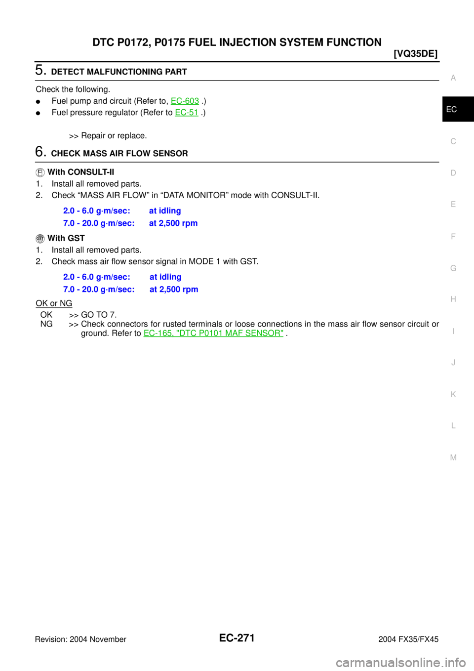
5. DETECT MALFUNCTIONING PART
Check the following.
�Fuel pump and circuit (Refer to, EC-603 .)
�Fuel pressure regulator (Refer to EC-51 .)
>> Repair or replace.
6. CHECK MASS AIR FLOW SENSOR
With CONSULT-II
1. Install all removed parts.
2. Check “MASS AIR FLOW” in “DATA MONITOR” mode with CONSULT-II.
With GST
1. Install all removed parts.
2. Check mass air flow sensor signal in MODE 1 with GST.
OK or NG
OK >> GO TO 7.
NG >> Check connectors for rusted terminals or loose connections in the mass air flow sensor circuit or
ground. Refer to EC-165, "
DTC P0101 MAF SENSOR" . 2.0 - 6.0 g·m/sec: at idling
7.0 - 20.0 g·m/sec: at 2,500 rpm
2.0 - 6.0 g·m/sec: at idling
7.0 - 20.0 g·m/sec: at 2,500 rpm
Page 1613 of 4449
![INFINITI FX35 2004 Service Manual EC-272
[VQ35DE]
DTC P0172, P0175 FUEL INJECTION SYSTEM FUNCTION
Revision: 2004 November 2004 FX35/FX45
7. CHECK FUNCTION OF INJECTORS
With CONSULT-II
1. Start engine.
2. Perform “POWER BALANCE” i](/manual-img/42/57021/w960_57021-1612.png "INFINITI FX35 2004 Service Manual EC-272
[VQ35DE]
DTC P0172, P0175 FUEL INJECTION SYSTEM FUNCTION
Revision: 2004 November 2004 FX35/FX45
7. CHECK FUNCTION OF INJECTORS
With CONSULT-II
1. Start engine.
2. Perform “POWER BALANCE” i")
EC-272
[VQ35DE]
DTC P0172, P0175 FUEL INJECTION SYSTEM FUNCTION
Revision: 2004 November 2004 FX35/FX45
7. CHECK FUNCTION OF INJECTORS
With CONSULT-II
1. Start engine.
2. Perform “POWER BALANCE” in “ACTIVE TEST” mode with
CONSULT-II.
3. Make sure that each circuit produces a momentary engine
speed drop.
Without CONSULT-II
1. Start engine.
2. Listen to each injector operating sound.
OK or NG
OK >> GO TO 8.
NG >> Perform trouble diagnosis for INJECTORS, EC-597
.
8. CHECK INJECTOR
1. Remove injector assembly. Refer to EM-45, "
FUEL INJECTOR AND FUEL TUBE" .
Keep fuel hose and all injectors connected to injector gallery.
2. Confirm that the engine is cooled down and there are no fire hazards near the vehicle.
3. Disconnect all injector harness connectors.
4. Disconnect all ignition coil harness connectors.
5. Prepare pans or saucers under each injectors.
6. Crank engine for about 3 seconds.
Make sure fuel does not drip from injector.
OK or NG
OK (Does not drip.)>>GO TO 9.
NG (Drips.)>>Replace the injectors from which fuel is dripping. Always replace O-ring with new one.
9. CHECK INTERMITTENT INCIDENT
Refer to EC-135, "
TROUBLE DIAGNOSIS FOR INTERMITTENT INCIDENT" .
>>INSPECTION END
PBIB0133E
Clicking noise should be heard.
PBIB1986E
Page 1657 of 4449
![INFINITI FX35 2004 Service Manual EC-316
[VQ35DE]
DTC P0420, P0430 THREE WAY CATALYST FUNCTION
Revision: 2004 November 2004 FX35/FX45
DTC P0420, P0430 THREE WAY CATALYST FUNCTIONPFP:20905
On Board Diagnosis LogicABS006QH
The ECM monit](/manual-img/42/57021/w960_57021-1656.png "INFINITI FX35 2004 Service Manual EC-316
[VQ35DE]
DTC P0420, P0430 THREE WAY CATALYST FUNCTION
Revision: 2004 November 2004 FX35/FX45
DTC P0420, P0430 THREE WAY CATALYST FUNCTIONPFP:20905
On Board Diagnosis LogicABS006QH
The ECM monit")
EC-316
[VQ35DE]
DTC P0420, P0430 THREE WAY CATALYST FUNCTION
Revision: 2004 November 2004 FX35/FX45
DTC P0420, P0430 THREE WAY CATALYST FUNCTIONPFP:20905
On Board Diagnosis LogicABS006QH
The ECM monitors the switching frequency ratio of heated oxygen sensors 1 and 2.
A three way catalyst 1 with high oxygen storage capacity will indicate a low switching frequency of heated oxy-
gen sensor 2. As oxygen storage capacity decreases, the heated oxygen sensor 2 switching frequency will
increase.
When the frequency ratio of heated oxygen sensors 1 and 2 approaches a specified limit value, the three way
catalyst 1 malfunction is diagnosed.
DTC Confirmation ProcedureABS006QI
NOTE:
If DTC Confirmation Procedure has been previously conducted, always turn ignition switch OFF and wait at
least 10 seconds before conducting the next test.
WITH CONSULT-II
TESTING CONDITION:
Do not hold engine speed for more than the specified minutes below.
1. Turn ignition switch ON and select “DATA MONITOR” mode with
CONSULT-II.
2. Start engine and warm it up to the normal operating tempera-
ture.
3. Turn ignition switch OFF and wait at least 10 seconds.
4. Start engine and keep the engine speed between 3,500 and
4,000 rpm for at least 1 minute under no load.
5. Let engine idle for 1 minute.
6. Make sure that “COOLAN TEMP/S” indicates more than 70°C
(158°F).
If not, warm up engine and go to next step when “COOLAN
TEMP/S” indication reaches to 70°C (158°F).
7. Open engine hood.
PBIB1166E
DTC No. Trouble diagnosis name DTC detecting condition Possible cause
P0420
0420
(Bank 1)
Catalyst system effi-
ciency below threshold
�Three way catalyst 1 does not operate prop-
erly.
�Three way catalyst 1 does not have enough
oxygen storage capacity.
�Three way catalyst 1
�Exhaust tube
�Intake air leaks
�Fuel injector
�Fuel injector leaks
�Spark plug
�Improper ignition timing P0430
0430
(Bank 2)
SEF189Y
![INFINITI FX35 2004 Service Manual DTC P0172, P0175 FUEL INJECTION SYSTEM FUNCTION
EC-267
[VQ35DE]
C
D
E
F
G
H
I
J
K
L
MA
EC
Revision: 2004 November 2004 FX35/FX45
Wiring DiagramABS006P4
BANK 1
TBWM0294E](/manual-img/42/57021/w960_57021-1607.png "INFINITI FX35 2004 Service Manual DTC P0172, P0175 FUEL INJECTION SYSTEM FUNCTION
EC-267
[VQ35DE]
C
D
E
F
G
H
I
J
K
L
MA
EC
Revision: 2004 November 2004 FX35/FX45
Wiring DiagramABS006P4
BANK 1
TBWM0294E")
![INFINITI FX35 2004 Service Manual EC-268
[VQ35DE]
DTC P0172, P0175 FUEL INJECTION SYSTEM FUNCTION
Revision: 2004 November 2004 FX35/FX45
BANK 2
TBWM0295E](/manual-img/42/57021/w960_57021-1608.png "INFINITI FX35 2004 Service Manual EC-268
[VQ35DE]
DTC P0172, P0175 FUEL INJECTION SYSTEM FUNCTION
Revision: 2004 November 2004 FX35/FX45
BANK 2
TBWM0295E")
![INFINITI FX35 2004 Service Manual DTC P0172, P0175 FUEL INJECTION SYSTEM FUNCTION
EC-269
[VQ35DE]
C
D
E
F
G
H
I
J
K
L
MA
EC
Revision: 2004 November 2004 FX35/FX45
Diagnostic ProcedureABS006P5
1. CHECK EXHAUST GAS LEAK
1. Start engine](/manual-img/42/57021/w960_57021-1609.png "INFINITI FX35 2004 Service Manual DTC P0172, P0175 FUEL INJECTION SYSTEM FUNCTION
EC-269
[VQ35DE]
C
D
E
F
G
H
I
J
K
L
MA
EC
Revision: 2004 November 2004 FX35/FX45
Diagnostic ProcedureABS006P5
1. CHECK EXHAUST GAS LEAK
1. Start engine")