Page 4394 of 4449

PRECAUTION
WW-3
C
D
E
F
G
H
I
J
L
MA
B
WW
Revision: 2004 November 2004 FX35/FX45
PRECAUTIONPFP:00011
Precautions for Supplemental Restraint System (SRS) “AIR BAG” and “SEAT
BELT PRE-TENSIONER”
AKS007KQ
The Supplemental Restraint System such as “AIR BAG” and “SEAT BELT PRE-TENSIONER”, used along
with a front seat belt, helps to reduce the risk or severity of injury to the driver and front passenger for certain
types of collision. This system includes seat belt switch inputs and dual stage front air bag modules. The SRS
system uses the seat belt switches to determine the front air bag deployment, and may only deploy one front
air bag, depending on the severity of a collision and whether the front occupants are belted or unbelted.
Information necessary to service the system safely is included in the SRS and SB section of this Service Man-
ual.
WARNING:
�To avoid rendering the SRS inoperative, which could increase the risk of personal injury or death
in the event of a collision which would result in air bag inflation, all maintenance must be per-
formed by an authorized NISSAN/INFINITI dealer.
�Improper maintenance, including incorrect removal and installation of the SRS, can lead to per-
sonal injury caused by unintentional activation of the system. For removal of Spiral Cable and Air
Bag Module, see the SRS section.
�Do not use electrical test equipment on any circuit related to the SRS unless instructed to in this
Service Manual. SRS wiring harnesses can be identified by yellow and/or orange harnesses or
harness connectors.
Wiring Diagrams and Trouble DiagnosisAKS0056N
When you read Wiring diagrams, refer to the following:
�Refer to GI-15, "How to Read Wiring Diagrams" .
�Refer to PG-3, "POWER SUPPLY ROUTING CIRCUIT" for power distribution circuit.
When you perform trouble diagnosis, refer to the following:
�Refer to GI-11, "How to Follow Trouble Diagnoses" .
�Refer to GI-27, "How to Perform Efficient Diagnosis for an Electrical Incident" .
Page 4408 of 4449

FRONT WIPER AND WASHER SYSTEM
WW-17
C
D
E
F
G
H
I
J
L
MA
B
WW
Revision: 2004 November 2004 FX35/FX45
CONSULT-II Functions (BCM)AKS007AD
CONSULT-II can display each diagnostic item using the following diagnostic test modes: work support, self-
diagnostic results, data monitor and active test through data reception and command transmission via the
BCM CAN communication line.
CONSULT-II OPERATION
CAUTION:
If CONSULT-II is used with no connection of CONSULT-II CONVERTER, malfunctions might be
detected in self-diagnosis depending on control unit which carry out CAN communication.
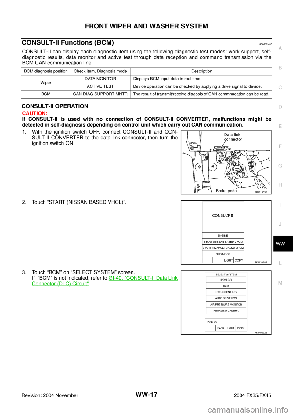
1. With the ignition switch OFF, connect CONSULT-II and CON-
SULT-II CONVERTER to the data link connector, then turn the
ignition switch ON.
2. Touch “START (NISSAN BASED VHCL)”.
3. Touch “BCM” on “SELECT SYSTEM” screen.
If “BCM” is not indicated, refer to GI-40, "
CONSULT-II Data Link
Connector (DLC) Circuit" .
BCM diagnosis position Check item, Diagnosis mode Description
WiperDATA MONITOR Displays BCM input data in real time.
ACTIVE TEST Device operation can be checked by applying a drive signal to device.
BCM CAN DIAG SUPPORT MNTR The result of transmit/receive diagosis of CAN commnucation can be read.
PBIB1503E
SKIA3098E
PKIA5222E
Page 4410 of 4449

FRONT WIPER AND WASHER SYSTEM
WW-19
C
D
E
F
G
H
I
J
L
MA
B
WW
Revision: 2004 November 2004 FX35/FX45
ACTIVE TEST
Operation Procedure
1. Touch “WIPER” on the “SELECT TEST ITEM” screen.
2. Touch “ACTIVE TEST” on “SELECT DIAG MODE” screen.
3. Touch items to be tested, and check operation.
4. During operation check, touching “STOP” deactivates operation.
Display Item List
CONSULT-II Functions (IPDM E/R)AKS007AE
CONSULT-II can display each diagnostic item using the following diagnostic test modes: work support, self-
diagnostic results, data monitor and active test through data reception and command transmission via the
IPDM E/R CAN communication line.
CONSULT-II OPERATION
CAUTION:
If CONSULT-II is used with no connection of CONSULT-II CONVERTER, malfunctions might be
detected in self-diagnosis depending on control unit which carry out CAN communication.
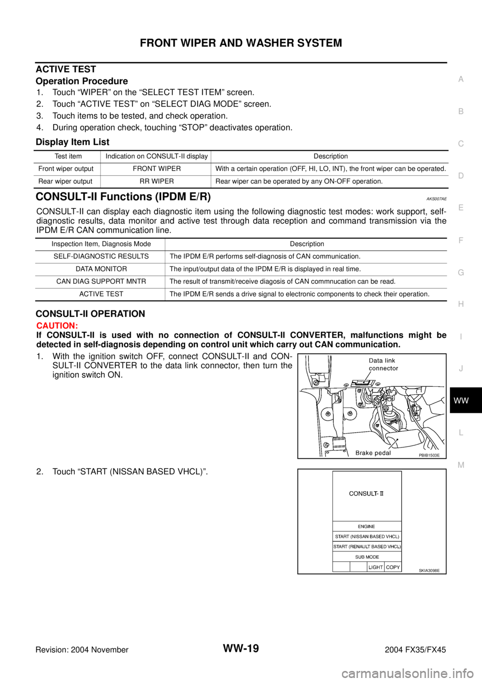
1. With the ignition switch OFF, connect CONSULT-II and CON-
SULT-II CONVERTER to the data link connector, then turn the
ignition switch ON.
2. Touch “START (NISSAN BASED VHCL)”.
Test item Indication on CONSULT-II display Description
Front wiper output FRONT WIPER With a certain operation (OFF, HI, LO, INT), the front wiper can be operated.
Rear wiper output RR WIPER Rear wiper can be operated by any ON-OFF operation.
Inspection Item, Diagnosis Mode Description
SELF-DIAGNOSTIC RESULTS The IPDM E/R performs self-diagnosis of CAN communication.
DATA MONITOR The input/output data of the IPDM E/R is displayed in real time.
CAN DIAG SUPPORT MNTR The result of transmit/receive diagosis of CAN commnucation can be read.
ACTIVE TEST The IPDM E/R sends a drive signal to electronic components to check their operation.
PBIB1503E
SKIA3098E
Page 4432 of 4449

REAR WIPER AND WASHER SYSTEM
WW-41
C
D
E
F
G
H
I
J
L
MA
B
WW
Revision: 2004 November 2004 FX35/FX45
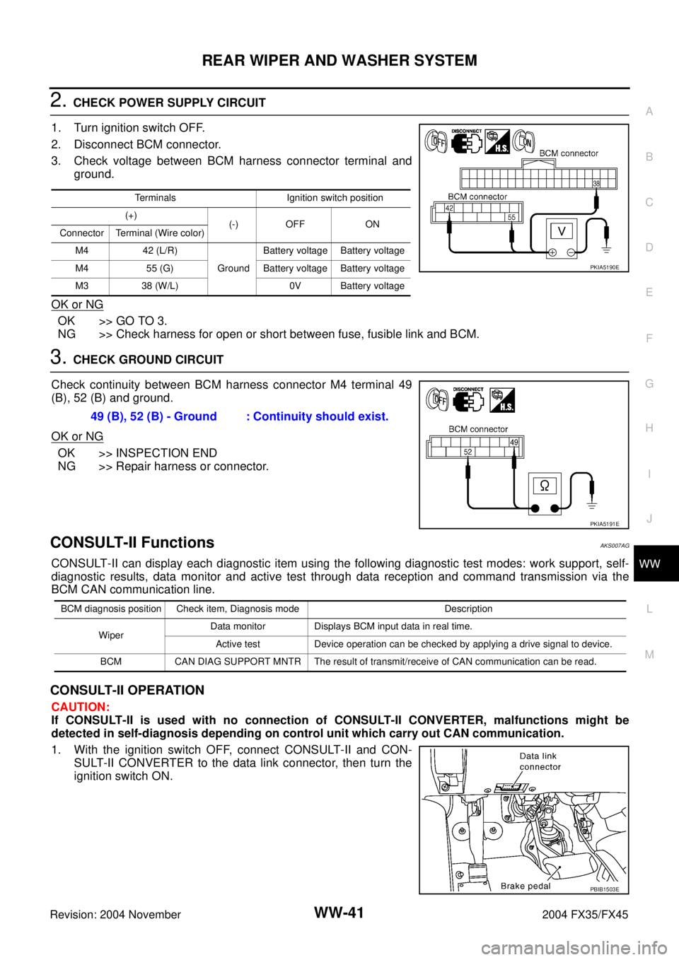
2. CHECK POWER SUPPLY CIRCUIT
1. Turn ignition switch OFF.
2. Disconnect BCM connector.
3. Check voltage between BCM harness connector terminal and
ground.
OK or NG
OK >> GO TO 3.
NG >> Check harness for open or short between fuse, fusible link and BCM.
3. CHECK GROUND CIRCUIT
Check continuity between BCM harness connector M4 terminal 49
(B), 52 (B) and ground.
OK or NG
OK >> INSPECTION END
NG >> Repair harness or connector.
CONSULT-II FunctionsAKS007AG
CONSULT-II can display each diagnostic item using the following diagnostic test modes: work support, self-
diagnostic results, data monitor and active test through data reception and command transmission via the
BCM CAN communication line.
CONSULT-II OPERATION
CAUTION:
If CONSULT-II is used with no connection of CONSULT-II CONVERTER, malfunctions might be
detected in self-diagnosis depending on control unit which carry out CAN communication.
1. With the ignition switch OFF, connect CONSULT-II and CON-
SULT-II CONVERTER to the data link connector, then turn the
ignition switch ON.
Terminals Ignition switch position
(+)
(-) OFF ON
Connector Terminal (Wire color)
M4 42 (L/R)
GroundBattery voltage Battery voltage
M4 55 (G) Battery voltage Battery voltage
M3 38 (W/L) 0V Battery voltage
PKIA5190E
49 (B), 52 (B) - Ground : Continuity should exist.
PKIA5191E
BCM diagnosis position Check item, Diagnosis mode Description
WiperData monitor Displays BCM input data in real time.
Active test Device operation can be checked by applying a drive signal to device.
BCM CAN DIAG SUPPORT MNTR The result of transmit/receive of CAN communication can be read.
PBIB1503E
Page 4444 of 4449
CIGARETTE LIGHTER
WW-53
C
D
E
F
G
H
I
J
L
MA
B
WW
Revision: 2004 November 2004 FX35/FX45
Removal and Installation of Cigarette LighterAKS007AB
REMOVAL
1. Remove A/T console finisher. Refer to IP-12, "(F) A/T Console
Finisher" in “IP” section.
2. Remove instrument ashtray and hazard switch. Refer to IP-17,
"A/T CONSOLE FINISHER" in “IP” section.
3. Pull out the cigarette lighter.
4. Use a screwdriver to undo ashtray finisher hooks.
5. Remove screws and remove socket.
INSTALLATION
Install in the reverse order of removal.
SKIA5092E
SKIA5091E