Page 2604 of 4449
IGNITION SIGNAL
EC-1263
[VK45DE]
C
D
E
F
G
H
I
J
K
L
MA
EC
Revision: 2004 November 2004 FX35/FX45
Wiring DiagramABS00CEK
TBWM0261E
Page 2609 of 4449
![INFINITI FX35 2004 Service Manual EC-1268
[VK45DE]
IGNITION SIGNAL
Revision: 2004 November 2004 FX35/FX45
Specification data are reference values and are measured between each terminal and ground.
Pulse signal is measured by CONSULT-I](/manual-img/42/57021/w960_57021-2608.png "INFINITI FX35 2004 Service Manual EC-1268
[VK45DE]
IGNITION SIGNAL
Revision: 2004 November 2004 FX35/FX45
Specification data are reference values and are measured between each terminal and ground.
Pulse signal is measured by CONSULT-I")
EC-1268
[VK45DE]
IGNITION SIGNAL
Revision: 2004 November 2004 FX35/FX45
Specification data are reference values and are measured between each terminal and ground.
Pulse signal is measured by CONSULT-II.
CAUTION:
Do not use ECM ground terminals when measuring input/output voltage. Doing so may result in dam-
age to the ECM's transistor. Use a ground other than ECM terminals, such as the ground.
: Average voltage for pulse signal (Actual pulse signal can be confirmed by oscilloscope.)
Diagnostic ProcedureABS00CEL
1. CHECK ENGINE START
Turn ignition switch OFF, and restart engine.
Is engine running?
Ye s o r N o
Yes (With CONSULT-II)>>GO TO 2.
Yes (Without CONSULT-II)>>GO TO 3.
No >> GO TO 4.
2. CHECK OVERALL FUNCTION
With CONSULT-II
1. Perform “POWER BALANCE” in “ACTIVE TEST” mode with
CONSULT-II.
2. Make sure that each circuit produces a momentary engine
speed drop.
OK or NG
OK >>INSPECTION END
NG >> GO TO 10.
TER-
MINAL
NO.WIRE
COLORITEM CONDITION DATA (DC Voltage)
65
79
80
81Y
LG
GY
GIgnition signal No. 8
Ignition signal No. 6
Ignition signal No. 4
Ignition signal No. 2[Engine is running]
�Warm-up condition
�Idle speed
NOTE:
The pulse cycle changes depending on rpm at
idle0 - 0.2V
[Engine is running]
�Warm-up condition
�Engine speed is 2,000 rpm0.1 - 0.4V
PBIB0044E
PBIB0045E
PBIB0133E
Page 2613 of 4449
![INFINITI FX35 2004 Service Manual EC-1272
[VK45DE]
IGNITION SIGNAL
Revision: 2004 November 2004 FX35/FX45
12. CHECK IGNITION COIL GROUND CIRCUIT FOR OPEN AND SHORT
1. Turn ignition switch OFF.
2. Check harness continuity between ignit](/manual-img/42/57021/w960_57021-2612.png "INFINITI FX35 2004 Service Manual EC-1272
[VK45DE]
IGNITION SIGNAL
Revision: 2004 November 2004 FX35/FX45
12. CHECK IGNITION COIL GROUND CIRCUIT FOR OPEN AND SHORT
1. Turn ignition switch OFF.
2. Check harness continuity between ignit")
EC-1272
[VK45DE]
IGNITION SIGNAL
Revision: 2004 November 2004 FX35/FX45
12. CHECK IGNITION COIL GROUND CIRCUIT FOR OPEN AND SHORT
1. Turn ignition switch OFF.
2. Check harness continuity between ignition coil terminal 2 and ground.
Refer to Wiring Diagram.
3. Also check harness for short to power.
OK or NG
OK >> GO TO 13.
NG >> Repair open circuit or short to power in harness or connectors.
13. CHECK IGNITION COIL OUTPUT SIGNAL CIRCUIT FOR OPEN AND SHORT
1. Disconnect ECM harness connector.
2. Check harness continuity between ECM terminals 46, 60, 61, 62, 65, 79, 80, 81 and ignition coil terminal
1.
Refer to Wiring Diagram.
3. Also check harness for short to ground and short to power.
OK or NG
OK >> GO TO 14.
NG >> Repair open circuit or short to ground or short to power in harness or connectors.
14. CHECK IGNITION COIL WITH POWER TRANSISTOR
Refer to EC-1272, "
Component Inspection" .
OK or NG
OK >> GO TO 15.
NG >> Replace ignition coil with power transistor.
15. CHECK INTERMITTENT INCIDENT
Refer to EC-784, "
TROUBLE DIAGNOSIS FOR INTERMITTENT INCIDENT" .
>>INSPECTION END
Component InspectionABS00CEM
IGNITION COIL WITH POWER TRANSISTOR
1. Turn ignition switch OFF.
2. Disconnect ignition coil harness connector.
3. Check resistance between ignition coil terminals as follows.
CONDENSER
1. Turn ignition switch OFF.
2. Disconnect condenser harness connector.Continuity should exist.
Continuity should exist.
Terminal No. (Polarity) Resistance Ω [at 25°C (77°F)]
1 and 2 Except 0 or ∞
1 and 3
Except 0
2 and 3
PBIB0847E
Page 2614 of 4449
IGNITION SIGNAL
EC-1273
[VK45DE]
C
D
E
F
G
H
I
J
K
L
MA
EC
Revision: 2004 November 2004 FX35/FX45
3. Check resistance between condenser terminals 1 and 2.
Removal and InstallationABS00CEN
IGNITION COIL WITH POWER TRANSISTOR
Refer to EM-185, "IGNITION COIL" .
Resistance Above 1 MΩ at 25°C (77°F)
PBIB0794E
Page 2615 of 4449
EC-1274
[VK45DE]
INJECTOR CIRCUIT
Revision: 2004 November 2004 FX35/FX45
INJECTOR CIRCUITPFP:16600
Component DescriptionABS00CEO
The fuel injector is a small, precise solenoid valve. When the ECM
supplies a ground to the injector circuit, the coil in the injector is
energized. The energized coil pulls the ball valve back and allows
fuel to flow through the injector into the intake manifold. The amount
of fuel injected depends upon the injection pulse duration. Pulse
duration is the length of time the injector remains open. The ECM
controls the injection pulse duration based on engine fuel needs.
CONSULT-II Reference Value in Data Monitor ModeABS00CEP
Specification data are reference values.
SEF375Z
MONITOR ITEM CONDITION SPECIFICATION
B/FUEL SCHDL See EC-780, "
TROUBLE DIAGNOSIS - SPECIFICATION VALUE" .
INJ PULSE-B1
INJ PULSE-B2
�Engine: After warming up
�Air conditioner switch: OFF
�Shift lever: N
�No loadIdle 2.3 - 2.9 msec
2,000 rpm 2.3 - 2.9 msec
Page 2616 of 4449
INJECTOR CIRCUIT
EC-1275
[VK45DE]
C
D
E
F
G
H
I
J
K
L
MA
EC
Revision: 2004 November 2004 FX35/FX45
Wiring DiagramABS00CEQ
TBWM0264E
Page 2617 of 4449
![INFINITI FX35 2004 Service Manual EC-1276
[VK45DE]
INJECTOR CIRCUIT
Revision: 2004 November 2004 FX35/FX45
Specification data are reference values and are measured between each terminal and ground.
Pulse signal is measured by CONSULT-](/manual-img/42/57021/w960_57021-2616.png "INFINITI FX35 2004 Service Manual EC-1276
[VK45DE]
INJECTOR CIRCUIT
Revision: 2004 November 2004 FX35/FX45
Specification data are reference values and are measured between each terminal and ground.
Pulse signal is measured by CONSULT-")
EC-1276
[VK45DE]
INJECTOR CIRCUIT
Revision: 2004 November 2004 FX35/FX45
Specification data are reference values and are measured between each terminal and ground.
Pulse signal is measured by CONSULT-II.
CAUTION:
Do not use ECM ground terminals when measuring input/output voltage. Doing so may result in dam-
age to the ECM's transistor. Use a ground other than ECM terminals, such as the ground.
: Average voltage for pulse signal (Actual pulse signal can be confirmed by oscilloscope.)
Diagnostic ProcedureABS00CER
1. INSPECTION START
Turn ignition switch to START.
Is any cylinder ignited?
Ye s o r N o
Yes >> GO TO 2.
No >> GO TO 3.
TER-
MINAL
NO.WIRE
COLORITEM CONDITION DATA (DC Voltage)
21
22
23
40
41
42
44
63W
R
P
PU
BR
B
OR
GInjector No. 5
Injector No. 3
Injector No. 1
Injector No. 6
Injector No. 4
Injector No. 2
Injector No. 7
Injector No. 8[Engine is running]
�Warm-up condition
�Idle speed
NOTE:
The pulse cycle changes depending on rpm at idleBATTERY VOLTAGE
(11 - 14V)
[Engine is running]
�Warm-up condition
�Engine speed is 2,000 rpmBATTERY VOLTAGE
(11 - 14V)
PBIB0042E
PBIB0043E
Page 2620 of 4449
INJECTOR CIRCUIT
EC-1279
[VK45DE]
C
D
E
F
G
H
I
J
K
L
MA
EC
Revision: 2004 November 2004 FX35/FX45
6. DETECT MALFUNCTIONING PART
Check the following.
�Harness connectors F21, F201
�Harness connectors F41, F221
�Harness for open or short between injector and ECM
>> Repair open circuit or short to ground or short to power in harness or connectors.
7. CHECK INJECTOR
Refer to EC-1279, "
Component Inspection" .
OK or NG
OK >> GO TO 8.
NG >> Replace injector.
8. CHECK INTERMITTENT INCIDENT
Refer to EC-784, "
TROUBLE DIAGNOSIS FOR INTERMITTENT INCIDENT" .
>>INSPECTION END
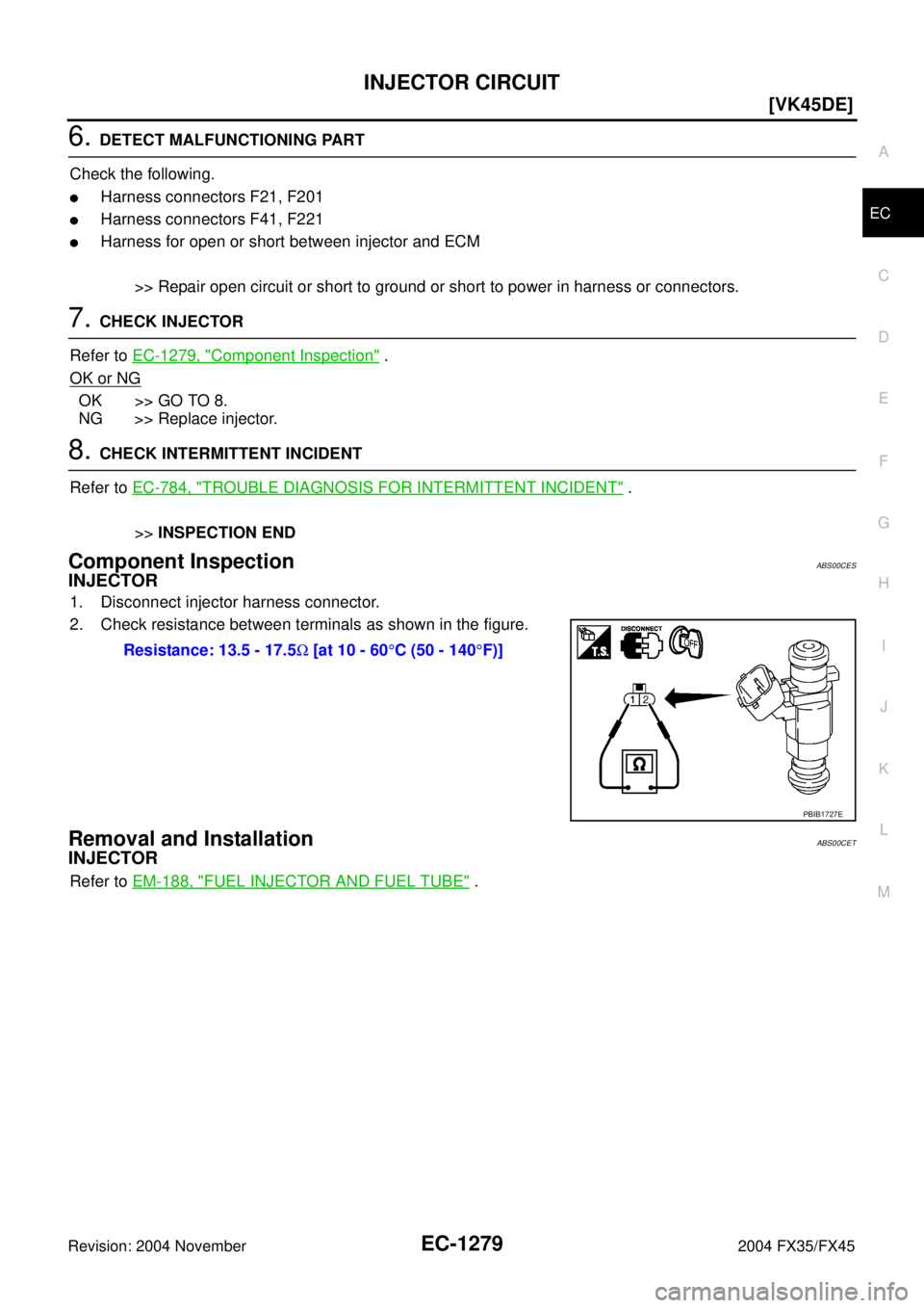
Component InspectionABS00CES
INJECTOR
1. Disconnect injector harness connector.
2. Check resistance between terminals as shown in the figure.
Removal and InstallationABS00CET
INJECTOR
Refer to EM-188, "FUEL INJECTOR AND FUEL TUBE" . Resistance: 13.5 - 17.5Ω [at 10 - 60°C (50 - 140°F)]
PBIB1727E
![INFINITI FX35 2004 Service Manual IGNITION SIGNAL
EC-1263
[VK45DE]
C
D
E
F
G
H
I
J
K
L
MA
EC
Revision: 2004 November 2004 FX35/FX45
Wiring DiagramABS00CEK
TBWM0261E](/manual-img/42/57021/w960_57021-2603.png "INFINITI FX35 2004 Service Manual IGNITION SIGNAL
EC-1263
[VK45DE]
C
D
E
F
G
H
I
J
K
L
MA
EC
Revision: 2004 November 2004 FX35/FX45
Wiring DiagramABS00CEK
TBWM0261E")
![INFINITI FX35 2004 Service Manual IGNITION SIGNAL
EC-1273
[VK45DE]
C
D
E
F
G
H
I
J
K
L
MA
EC
Revision: 2004 November 2004 FX35/FX45
3. Check resistance between condenser terminals 1 and 2.
Removal and InstallationABS00CEN
IGNITION COI](/manual-img/42/57021/w960_57021-2613.png "INFINITI FX35 2004 Service Manual IGNITION SIGNAL
EC-1273
[VK45DE]
C
D
E
F
G
H
I
J
K
L
MA
EC
Revision: 2004 November 2004 FX35/FX45
3. Check resistance between condenser terminals 1 and 2.
Removal and InstallationABS00CEN
IGNITION COI")
![INFINITI FX35 2004 Service Manual EC-1274
[VK45DE]
INJECTOR CIRCUIT
Revision: 2004 November 2004 FX35/FX45
INJECTOR CIRCUITPFP:16600
Component DescriptionABS00CEO
The fuel injector is a small, precise solenoid valve. When the ECM
supp](/manual-img/42/57021/w960_57021-2614.png "INFINITI FX35 2004 Service Manual EC-1274
[VK45DE]
INJECTOR CIRCUIT
Revision: 2004 November 2004 FX35/FX45
INJECTOR CIRCUITPFP:16600
Component DescriptionABS00CEO
The fuel injector is a small, precise solenoid valve. When the ECM
supp")
![INFINITI FX35 2004 Service Manual INJECTOR CIRCUIT
EC-1275
[VK45DE]
C
D
E
F
G
H
I
J
K
L
MA
EC
Revision: 2004 November 2004 FX35/FX45
Wiring DiagramABS00CEQ
TBWM0264E](/manual-img/42/57021/w960_57021-2615.png "INFINITI FX35 2004 Service Manual INJECTOR CIRCUIT
EC-1275
[VK45DE]
C
D
E
F
G
H
I
J
K
L
MA
EC
Revision: 2004 November 2004 FX35/FX45
Wiring DiagramABS00CEQ
TBWM0264E")