2004 Hyundai Terracan fuel
[x] Cancel search: fuelPage 165 of 361

DO-IT-YOURSELF MAINTENANCE 6-13
G110D03Y
Fluid level should be within "HOT" range
WARNING: The cooling fan is controlled by engine cool-ant temperature and may sometimes oper- ate even when the engine is not running. Use extreme caution when working near the blades of the cooling fan, so that you are not injured by a rotating fan blade. As the en- gine coolant temperature decreases, the fan will automatically shut off. This is a normal condition. WARNING (Diesel only): Never work on injection system with enginerunning or within 30 seconds after shutting off engine. High pressure pump, rail, injec- tors and high pressure pipes are subjected to high pressure even after the engine has been switched off. The fuel jet produced by fuel leaks may cause serious injury, if it contacts with the body. People using pace- makers should not move closer than 30cm to the ECU or wiring harness within the
Park the car on level ground with the parking brake engaged. When the transmission fluid level is checked, the transmission fluid should be at normal operating temperature and the engine idling.
While the engine is idling, apply the brakes and move the gear selector lever from "P" to each of its other positions — "R", "N", "D", "2", "L" — and then return to "N" or "P". With the engine still idling:
1. Open the hood, being careful to keep hands,
long hair and clothing clear of any moving parts.
2. Remove the transmission dipstick, wipe it clean, reinsert the dipstick as far as it will go,then remove it again. Now check the fluid level on the dipstick. It should be in the "HOT" range on the dipstick.
3. If the transmission fluid level is low, use a funnel to add transmission fluid through thedipstick tube until the level reaches the "HOT" range. Do not overfill.
G110D01HP-D
Gasoline
Diesel (2.9 CRDi)
Diesel (2.5 TCI)
G110D02HP
Page 173 of 361
DO-IT-YOURSELF MAINTENANCE 6-21
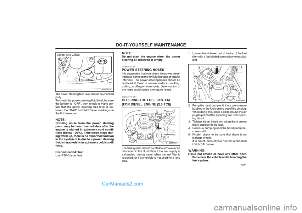
G350A01HP-GAT BLEEDING THE FUEL SYSTEM
(FOR DIESEL ENGINE (2.5 TCI))
E090A01HP
The fuel system should be bled to remove air as described in the illustration if the fuel supply is exhausted during travel, when the fuel filter is replaced, or if the vehicle is not used for a long time.
G240A01A-AAT POWER STEERING HOSESIt is suggested that you check the power steer- ing hose connections for fluid leakage at regular intervals. The power steering hoses should be replaced if there is severe surface cracking, pulling, scuffing or worn spots. Deterioration of the hose could cause premature failure.
NOTE: Do not start the engine when the powersteering oil reservoir is empty.
2. Pump the hand pump until there are no more
bubbles in the fuel coming out of the air plug. When doing this, place a cloth around the air plug to prevent the escaping fuel from spew- ing about.
3. Tighten the air bleed bolt when there are no more bubbles in the fuel.
4. Continue pumping until the hand pump be- comes stiff.
5. Finally, check to be sure that there is no leakage of fuel.If in doubt, consult your nearest authorizedHYUNDAI dealer.
WARNING:
(1) Do not smoke or have any other open flame near the vehicle while bleeding the fuel system.
E090A02HP
1. Loosen the air bleed bolt at the top of the fuel
filter with a flat-bladed screwdriver or equiva- lent.
The power steering fluid level should be checked daily. To check the power steering fluid level, be surethe ignition is "OFF", then check to make cer- tain that the power steering fluid level is be- tween the "MAX" and "MIN" level markings on the fluid reservoir. NOTE: Grinding noise from the power steering pump may be heard immediately after the engine is started in extremely cold condi- tions (below - 20°C). If the noise stops dur- ing warm up, there is no abnormal function in the system. If is due to a power steering fluid characteristic in extremely cold condi- tions. Recommended Fluid Use PSF-3 type fluid.
G230A02HP
Diesel (2.9 CRDi)
Page 174 of 361
DO-IT-YOURSELF MAINTENANCE
6-22
G350B01HP-GAT
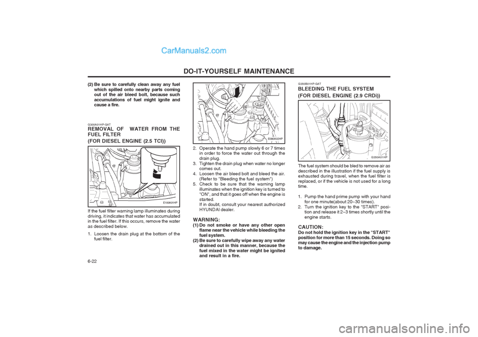
BLEEDING THE FUEL SYSTEM
(FOR DIESEL ENGINE (2.9 CRDi))
The fuel system should be bled to remove air as described in the illustration if the fuel supply is exhausted during travel, when the fuel filter is replaced, or if the vehicle is not used for a long time.
1. Pump the hand prime pump with your hand for one minute(about 20~30 times).
2. Turn the ignition key to the "START" posi- tion and release it 2~3 times shortly until the engine starts.
CAUTION:Do not hold the ignition key in the "START"position for more than 15 seconds. Doing so may cause the engine and the injection pump to damage.
G350A01HP
E090A02HP
2. Operate the hand pump slowly 6 or 7 times in order to force the water out through the drain plug.
3. Tighten the drain plug when water no longer comes out.
4. Loosen the air bleed bolt and bleed the air. (Refer to "Bleeding the fuel system")
5. Check to be sure that the warning lamp
illuminates when the ignition key is turned to "ON", and that it goes off when the engine is started. If in doubt, consult your nearest authorized HYUNDAI dealer.
WARNING:
(1) Do not smoke or have any other open flame near the vehicle while bleeding thefuel system.
(2) Be sure to carefully wipe away any water drained out in this manner, because thefuel mixed in the water might be ignited and result in a fire.
G300A01HP-GATREMOVAL OF WATER FROM THE FUEL FILTER (FOR DIESEL ENGINE (2.5 TCI))
E100A01HP
If the fuel filter warning lamp illuminates during driving, it indicates that water has accumulated in the fuel filter. If this occurs, remove the water as described below.
1. Loosen the drain plug at the bottom of the fuel filter.
(2) Be sure to carefully clean away any fuel
which spilled onto nearby parts coming out of the air bleed bolt, because such
accumulations of fuel might ignite andcause a fire.
Page 175 of 361
DO-IT-YOURSELF MAINTENANCE 6-23
G260A01HP-GAT
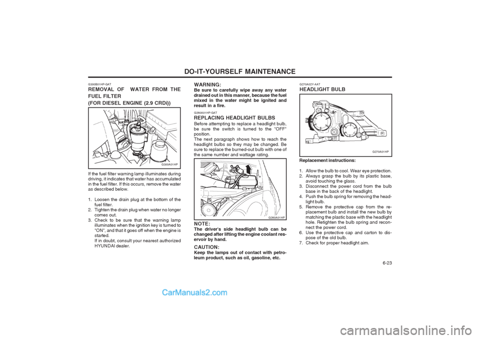
REPLACING HEADLIGHT BULBS Before attempting to replace a headlight bulb,
be sure the switch is turned to the "OFF" position. The next paragraph shows how to reach the
headlight bulbs so they may be changed. Besure to replace the burned-out bulb with one of the same number and wattage rating. WARNING:Be sure to carefully wipe away any water
drained out in this manner, because the fuel mixed in the water might be ignited and result in a fire.
NOTE:The driver's side headlight bulb can be
changed after lifting the engine coolant res-ervoir by hand.
CAUTION:Keep the lamps out of contact with petro-
leum product, such as oil, gasoline, etc.
G260A01HP Replacement instructions:
1. Allow the bulb to cool. Wear eye protection.
2. Always grasp the bulb by its plastic base, avoid touching the glass.
3. Disconnect the power cord from the bulb base in the back of the headlight.
4. Push the bulb spring for removing the head-
light bulb.
5. Remove the protective cap from the re- placement bulb and install the new bulb bymatching the plastic base with the headlight hole. Retighten the bulb spring and recon- nect the power cord.
6. Use the protective cap and carton to dis- pose of the old bulb.
7. Check for proper headlight aim. G270A02Y-AAT HEADLIGHT BULB
G270A01HP
G300B01HP-GAT REMOVAL OF WATER FROM THE FUEL FILTER
(FOR DIESEL ENGINE (2.9 CRDi))
G300A01HP
If the fuel filter warning lamp illuminates during driving, it indicates that water has accumulated in the fuel filter. If this occurs, remove the water as described below.
1. Loosen the drain plug at the bottom of the fuel filter.
2. Tighten the drain plug when water no longer
comes out.
3. Check to be sure that the warning lamp illuminates when the ignition key is turned to "ON", and that it goes off when the engine is started. If in doubt, consult your nearest authorizedHYUNDAI dealer.
Page 176 of 361

DO-IT-YOURSELF MAINTENANCE
6-24 6. Draw the vertical line (through the center of
each headlight) and the horizontal line (through the center of each headlight) on the aiming screen.
(1) Horizontal line dimension from ground :Low Beam : 894 mm (35.1 in.)
High Beam : 839 mm (33 in.)
(2) Distance between each vertical line : Low Beam : 1,316 mm (51.8 in.)
High Beam : 1,076 mm (42.4 in.)
And then, draw a parallel line at 38 mm (1.50 in.) under the horizontal line in case of adjusting the low beam or at 21 mm (0.83 in.) under the horizontal line in case of adjusting the high beam.
7. Adjust each cut-off line of the low beam to the parallel line with a phillips screwdriver - VERTICAL AIMING.
8. Adjust each cut-off line of the low beam to
the each vertical line with a phillips screw-driver - HORIZONTAL AIMING.
G290A01HP-GAT
HEADLIGHT AIMING ADJUSTMENT
G290A01HP
Horizontal aiming (Low Beam)
Vertical aiming (Low Beam)
Before performing aiming adjustment, make sure of the following.
1. Keep all tires inflated to the correct pres- sure.
2. Place the vehicle on level ground and press the front bumper & rear bumper down sev-eral times. Place vehicle at a distance of 3m (118.1 in.) from the test wall.
3. See that the vehicle is unloaded (except for
full levels of coolant, engine oil and fuel, andspare tire, jack, and tools). Have the driver or equivalent weight placed in driver's seat.
4. Clean the headlight lens and turn on the headlight.
5. Open the hood. Vertical aiming (High Beam)
Horizontal aiming(High Beam)
G270A02HP
WARNING: The halogen bulb contains gas under pres- sure and if impacted could shatter, resulting in flying fragments. Always wear eye pro- tection when servicing the bulb. Protect the bulb against abrasions or scratches and against liquids when lighted. Turn the bulb on only when installing in a headlight. Re- place the headlight if damaged or cracked. Keep the bulb out of the reach of children and dispose of the used bulb with care.
Page 179 of 361

EMISSION CONTROL SYSTEMS 7-1
7. EMISSION
CONTROL SYSTEMS
H010A01A-GAT EMISSION CONTROL SYSTEMS (If installed) Your Hyundai is equipped with an emission control system to meet all requirements of the Emission prohibition rules of your province. There are three emission control systems which are as follows. (1) Crankcase emission control system (For a Gasoline Engine)
(2) Evaporative emission control system (For a Gasoline Engine)
(3) Exhaust emission control system In order to assure the proper function of the emission control systems, it is recommended that you have your car inspected and main- tained by an authorized Hyundai dealer in ac- cordance with the maintenance schedule in this manual. H010C02Y-GAT 2. Evaporative Emission Control
System; For a Gasoline Engine
The Evaporative Emission Control System is
designed to prevent fuel vapors from escaping into the atmosphere. Canister While the engine is inoperative, fuel vapors
generated inside the fuel tank are absorbed and stored in the canister. When the engine is
running, the fuel vapors absorbed in the canis- ter are drawn into the induction system through the purge control solenoid valve. Purge Control Solenoid Valve The purge control solenoid valve is controlled
by the ECM; when the engine coolant tempera- ture is low, and during idling, it closes, so that evaporated fuel is not taken into the surge tank.
After engine warm-up, during ordinary driving, it opens so as to introduce evaporated fuel to the surge tank. H020A01A-AAT CATALYTIC CONVERTER ; For a Gasoline Engine
H020A01HP
Catalytic Converter
All Hyundai vehicles are equipped with a mono- lith type three-way catalytic converter to re- duce the carbon monoxide, hydrocarbons and nitrogen oxides contained in the exhaust gas. Exhaust gases passing through the catalytic converter may cause it to operate at a very high temperature. The introduction of large amounts of unburned gasoline into the exhaust may cause the catalytic converter to overheat and create a fire hazard. This risk may be reduced by observing the following:
H010B01A-AAT
1. Crankcase Emission Control System
; For a Gasoline Engine
The Positive Crankcase Ventilation System is employed to prevent air pollution caused by blow-by gases being emitted from the crank- case. This system supplies fresh filtered air to the crankcase through the air intake hose. Inside the crankcase, which the fresh air mixes with blow-by gases, which then pass through the PCV valve into the induction system.7
H010D01A-AAT
3. Exhaust Emission Control SystemThe Exhaust Emission Control System is a highly effective system which controls exhaust emissions while maintaining good vehicle performace.
Page 180 of 361

7-2EMISSION CONTROL SYSTEMS
WARNING:
o Use unleaded fuel only.
o Maintain the engine in good operating condition. Extremely high catalytic con-verter temperatures can result from im- proper operation of the electrical, igni- tion or multiport electronic fuel injection.
o If your engine stalls, pings, knocks, or is hard to start, have your Hyundai dealerinspect and repair the problem as soon as possible.
o Avoid driving with a very low fuel level. Running out of gasoline may cause theengine to misfire and result in damage to the catalytic converter.
o Avoid idling the engine for periods long- er than 10 minutes.
o The vehicle should not be pushed or pulled to get started. This may cause the catalytic converter to overheat and cre- ate a fire hazard.
o Do not touch the catalytic converter or any other part of the exhaust systemwhile the catalytic converter is hot. Shut off the engine, wait for at least one hour before touching the catalytic converter or any other part of the exhaust system.
o Remember that your Hyundai dealer is your best source of assistance.
o Do not stop your Hyundai over any com- bustible material such as grass, paper,leaves or rags. These materials might contact the hot catalytic converter and a fire might result. H020C01HP-GAT EGR SYSTEM ; For a Diesel Engine (If installed) This system helps control oxides of nitrogen by recirculating a part of the exhaust gas into the engine, there by reducing cylinder combustion temperature.The EGR system helps reduce Nox (Oxides of Nitrogen) emission gasses.
H020D01S-GAT CATALYTIC CONVERTER ; For a Diesel Engine (If installed) All Hyundai vehicles are equipped with oxida- tion type catalytic converter to reduce the car- bon monoxide, hydrocarbons and particulates contained in the exhaust gas.
Page 184 of 361

VEHICLE SPECIFICATIONS 9-1
GASOLINE
MF 68 AH
120 A (13.5 V)
9. VEHICLE SPECIFICATIONS J010A01HP-GAT MEASUREMENT
Overall length Overall width Overall height Wheel baseWheel tread
Front Rear
Type Wheel free playOil pump type
Ball and nut, torsion bar type (Integral type)0 ~ 30 mm (0 ~ 1.18 in.) Vane type
J020A01HP-GAT POWER STEERING
J050A02HP-GATBRAKE
Dual hydraulic with brake booster Ventilated disc Disc type Disc type (with ABS)Drum type (without ABS) Cable operated on rear wheel
Type Front brake type Rear brake typeParking brake
J060A01Y-GAT FUEL SYSTEM
Fuel tank capacity75 liter mm (in.)
4710 (185.4) 1860 (73.2) 1795 (70.6) 2750 (108.2)1530 (60.2) 1530 (60.2)
ITEM Battery Alternator
J040A02HP-GAT ELECTRICAL
2.5 TCI
MF 90 AH
90 A (12 V)
9
2.9 CRDi
MF 100 AH
110 A (12 V)
DIESEL
E.C only Except E.C
J030A02HP-GAT TIRE
Standard Spare
255/65 R16
Full Size