2004 Hyundai Grandeur engine coolant
[x] Cancel search: engine coolantPage 192 of 235

6- 10 DO-IT-YOURSELF MAINTENANCE
4. Turn the radiator cap counterclock-
wise without pressing down on it, until it stops. This relieves any pres-sure remaining in the cooling sys- tem. And remove the radiator cap by pushing down and turning coun-terclockwise.Now fill the radiator with clean dem-ineralized or distilled water. Con- tinue to add clean demineralized or distilled water in small quantitiesuntil the fluid level stays up in the radiator neck. G050D01L
G050D02L
5. Start the engine, top off the radia- tor with water and then add enginecoolant to the reservoir until the level is between "LOW" and "FULL".
6. Replace the radiator and reservoir
caps and check to be sure thedrain cocks are fully closed and not leaking.
WARNING:
The cooling fan is controlled by
engine coolant temperature andmay sometimes operate even when the engine is not running. Useextreme caution when working near the blades of the cooling fan so that you are not injured by a
3. Check Section 9 for the capacity of
the cooling system in your car.Then, following the manufacturer'sdirections on the engine coolant container, add the appropriate quantity of coolant to the radiator. rotating fan blade. As the engine coolant temperature decreases, the fan will automatically shut off. Thisis a normal condition.
G060A01L
G060A02L-GAT
SPARK PLUGS
Your engine was originally equipped
with platinum-tipped spark plugs. (If installed)
Platinum-tipped spark plugs will last
longer than conventional type sparkplugs and can be identified by blue lines on the ceramic shell.Unleaded: 1.0 ~ 1.1 mm (0.039 ~ 0.043 in.) Leaded: 0.7 ~ 0.8 mm (0.028 ~ 0.032 in.)
!
Page 197 of 235
DO-IT-YOURSELF MAINTENANCE 6- 15
G120A01A-AAT
CHECKING THE BRAKES
CAUTION:
Because brakes are essential to
the safe operation of the car, it is suggested that they be checked and inspected by your Hyundaidealer. The brakes should be checked and inspected for wear at those intervals specified in thevehicle maintenance schedule in Section 5.
G120B01A-A AT
Checking the Brake Fluid Level
WARNING:
Use caution when handling brakefluid. It can damage your vision if it gets into your eyes. It will alsodamage your vehicle's paint if spilled on it and not removed im- mediately.
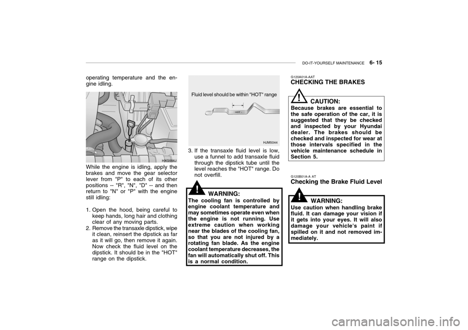
3. If the transaxle fluid level is low,
use a funnel to add transaxle fluidthrough the dipstick tube until the level reaches the "HOT" range. Do not overfill.
WARNING:
The cooling fan is controlled by
engine coolant temperature andmay sometimes operate even whenthe engine is not running. Use extreme caution when working near the blades of the cooling fan,so that you are not injured by a rotating fan blade. As the engine coolant temperature decreases, thefan will automatically shut off. This is a normal condition.
While the engine is idling, apply the
brakes and move the gear selector lever from "P" to each of its otherpositions -- "R", "N", "D" -- and then return to "N" or "P" with the engine still idling:
1. Open the hood, being careful to
keep hands, long hair and clothing clear of any moving parts.
2. Remove the transaxle dipstick, wipe it clean, reinsert the dipstick as far as it will go, then remove it again.Now check the fluid level on the dipstick. It should be in the "HOT" range on the dipstick. HXG556J
!
!
!
operating temperature and the en- gine idling.
HJM5044
Fluid level should be within "HOT" range
Page 205 of 235

DO-IT-YOURSELF MAINTENANCE 6- 23
G210A01A-AAT
CHECKING THE BATTERY
WARNING:
Batteries can be dangerous! When working with batteries, care-
fully observe the following pre- cautions to avoid serious injuries.
The fluid in the battery contains a
strong solution of sulfuric acid, whichis poisonous and highly corrosive. Be careful not to spill it on yourself or thecar. If you do spill battery fluid on yourself, immediately do the follow- ing:
o If battery fluid is on your skin, flush the affected areas with water for at least 15 minutes and then seek medical assistance.
o If battery fluid is in your eyes, rinse
out your eyes with water and getmedical assistance as soon as possible. While you are being driven to get medical assistance, continueto rinse your eyes by using a sponge or soft cloth saturated with water. o If you swallow battery fluid, drink a
large quantity of water or milk fol-lowed by milk of magnesia, eat araw egg or drink vegetable oil. Get medical assistance as soon as pos- sible.
While batteries are being charged(either by a battery charger or by the vehicle's generator), they produce explosive gases. Always observethese warnings to prevent injuries from occurring:
o Charge batteries only in a well ven- tilated area.
o Do not permit flames, sparks or
smoking in the area.
o Keep children away from the area. G210B01A-AAT Checking the Battery Keep the battery clean. Any evidence of corrosion around the battery posts or terminals should be removed using a solution of household baking sodaand warm water. After the battery terminals are dry, cover them with a light coating of grease.
!
G220A01A-AAT
CHECKING ELECTRIC COOL- ING FANS
WARNING:
The cooling fan is controlled by
engine coolant temperature and may sometimes operate even whenthe engine is not running. Use extreme caution when working near the blades of the cooling fan,so that you are not injured by a rotating fan blade. As the coolant temperature decreases the fan willautomatically shut off. This is a normal condition.
G220B01A-AAT
Checking Engine Cooling Fan
The engine cooling fan should come
on automatically if the engine coolanttemperature is high.
G220C01A-AAT
Checking Condenser Cooling Fan
The condenser cooling fan should
come on automatically whenever the air conditioning is in operation.
!
Page 207 of 235
DO-IT-YOURSELF MAINTENANCE 6- 25
Before performing aiming adjustment,
make sure of the following.
1. Keep all tires inflated to the correct
pressure.
2. Place the vehicle on level ground
and press the front bumper & rear bumper down several times. Place the vehicle at a distance of 3 m (118 in.) from the test wall.
3. See that the vehicle is unloaded (except for full levels of coolant,engine oil and fuel, and spare tire,jack, and tools). Have the driver or equivalent weight placed in driver's seat.
4. Clean the head light lenses and
turn on the headlights (low beam).
5. Open the hood.
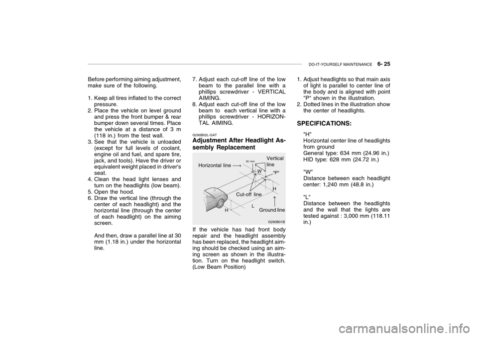
6. Draw the vertical line (through the center of each headlight) and the horizontal line (through the center of each headlight) on the aimingscreen. And then, draw a parallel line at 30 mm (1.18 in.) under the horizontal line. G290B02L-GAT
Adjustment After Headlight As- sembly Replacement
If the vehicle has had front body
repair and the headlight assembly has been replaced, the headlight aim- ing should be checked using an aim-ing screen as shown in the illustra- tion. Turn on the headlight switch. (Low Beam Position)
7. Adjust each cut-off line of the low
beam to the parallel line with aphillips screwdriver - VERTICALAIMING.
8. Adjust each cut-off line of the low
beam to each vertical line with a phillips screwdriver - HORIZON- TAL AIMING. 1. Adjust headlights so that main axis
of light is parallel to center line ofthe body and is aligned with point"P" shown in the illustration.
2. Dotted lines in the illustration show
the center of headlights.
SPECIFICATIONS: "H"Horizontal center line of headlightsfrom groundGeneral type: 634 mm (24.96 in.) HID type: 628 mm (24.72 in.) "W" Distance between each headlightcenter: 1,240 mm (48.8 in.) "L" Distance between the headlightsand the wall that the lights aretested against : 3,000 mm (118.11 in.)
G290B01B
L W
Cut-off line Ground line
"P"
Horizontal line
Vertical line30 mm
H H
Page 219 of 235

7- 2 EMISSION CONTROL SYSTEMS
H010A01A-GAT
EMISSION CONTROL SYSTEM (If Installed)
Your Hyundai is equipped with an
emission control system to meet all requirements of the Emission prohibi-tion rules of your province.
There are three emission control sys-
tems which are as follows.
1) Crankcase emission control sys-
tem
2) Evaporative emission control sys-
tem
3) Exhaust emission control system
In order to assure the proper function
of the emission control systems, it is recommended that you have your car inspected and maintained by an au-thorized Hyundai dealer in accordance with the maintenance schedule in this manual. H010B01A-AAT
1. Crankcase Emission Control
System
The positive crankcase ventilation
system is employed to prevent airpollution caused by blow-by gasesbeing emitted from the crankcase. This system supplies fresh air to the crankcase through the air intake hose.Inside the crankcase, the fresh air mixes with blow-by gases, which then pass through the PCV valve and intothe induction system.
H010C02Y-GAT
2. Evaporative Emission
Control System
The Evaporative Emission Control
System is designed to prevent fuel vapors from escaping into the atmo- sphere. Canister
While the engine is inoperative, fuel
vapors generated inside the fuel tank are absorbed and stored in the canis- ter. When the engine is running, the fuel vapors absorbed in the canisterare drawn into the induction system through the purge control solenoidvalve. Purge Control Solenoid Valve
The purge control solenoid valve is
controlled by the ECM; when the en- gine coolant temperature is low, and during idling, it closes, so that evapo- rated fuel is not taken into the surgetank. After engine warm-up, during ordinary driving, it opens so as to introduce evaporated fuel to the surgetank.
H010D01A-AAT
3. Exhaust Emission Control
System
The exhaust emission control system
is a highly effective system whichcontrols exhaust emission while main- taining good vehicle performance.
H010E01Y-GAT
EGR System
This system helps control nitrogen
oxides by recirculating a part of the exhaust gas into the engine, therebyreducing cylinder combustion tem- perature.
Page 229 of 235

9- 4 VEHICLE SPECIFICATIONS
Oil & Grease Standard
API SJ, SL or ABOVE, SAE 5W-20, 5W-30
ILSAC GF-3 or ABOVE SAE 10W-30 (ABOVE -18°C) SAE 15W-40 (ABOVE -13°C) SAE 20W-50 (ABOVE -7°C)
Normal driving conditionSevere driving conditionHYUNDAI GENUINE PARTS MTF 75W/85 (API GL-4)HYUNDAI GENUINE ATF SP III, DIAMOND ATF SP III, SK ATF SP III or other brands approved by Hyundai Motor Co., Ethylene glycol, base for aluminumPSF-3 DOT 3, DOT 4 or Equivalent
J080A04L-GAT LUBRICATION CHART
Item
Engine Oil Engine oil consumption Transaxle Coolant Power steering gear Brakes and clutch fluidQ'ty (liter)
Drain and refill (With oil filter) 3.5 L / 3.0 L : 4.3 2.5 L : 4.5 MAX. 1L / 1500 Km MAX. 1L / 1000 Km2.1 7.8 (2.5L), 8.5 (3.0L / 3.5L)9.5 (2.5L), 11.2 (3.0L / 3.5L) 1.0 As required
Manual Auto
Page 232 of 235

INDEX 10- 3
D Defrosting / Defogging .............................................. 1-85
Door Door locks ................................................................ 1-6
Door courtesy light ................................................. 1-73
Locking and unlocking front doors with a key ......... 1-6
Drink Holder .............................................................. 1-58
Drive Belts ...................................................... 6-18, 6-21
Driving Economical driving ..................................... 2-14 ~ 2-15 Smooth cornering ................................................... 2-15
Winter driving ......................................................... 2-16
EEmission Control System ................................. 7-1 ~ 7-3
Engine
Before starting the engine ....................................... 2-3
Compartment ................................................... 6-1~6-3
Coolant ......................................................... 6-8 ~ 6-10
Coolant temperature gauge ................................... 1-47
If the engine overheats ............................................ 3-4
Number .................................................................... 8-2
Oil ............................................................................. 6-6
Starting ..................................................................... 2-4
Engine Exhaust Can Be Dangerous ........................... 2-2F
Fan Speed Control .......................................... 1-81, 1-90 Fog Light
Front ....................................................................... 1-49
Rear ........................................................... 1-49 ~ 1-50
Front Seats
Adjustable front seats ............................................ 1-11
Adjustable headrest s .............................................. 1-13
Adjusting seat forward and rearward ......... 1-11 ~ 1-12 Adjusting seatback angle .......................................1-12
Lumbar support control .................. ........................ 1-13
Seat cushion height adjustment............................ 1-14
Seat warmer ........................................................... 1-17
Fuel
Capacity ................................................................... 9-2
Gauge .................................................................... 1-47
recommendations ..................................................... 1-2
Fuel Filler Lid
Remote release ...................................................... 1-69
Manual ................................................................... 1-70
Fuses ............................................................ 6-21 ~ 6-22 G General Checks .......................................................... 6-5
Glove Box ................................................................. 1-63