Page 364 of 445
3. WHAT TO DO IN AN EMERGENCYIf the engine will not start ....................... ......................................... 3-2
Jump starting ...................................... ............................................ 3-3
If the engine overheats ................................................... ................ 3-4
Spare tyre ................................................... .................................... 3-5
In the event of a pun cture .............................................. ................. 3-6
Vehicle Towing or Recovery ........................................... ..............3-11
Emergency tow ing ................................................ ........................3-13
If you lose your keys ................................................... ..................3-13
3
tbuk-3.p65 3/23/04, 4:24 PM
1
Page 375 of 445

3- 12 WHAT TO DO IN AN EMERGENCY
!
CAUTION:
The following restriction must be
observed in order to avoid serious
damage to the transaxle .
The vehicle must never be towed
from the rear with the front wheels
on the ground.
The vehicle must not be towed until
transaxle fluid has been added to
bring the level up to the "HOT"
marking on the dipstick. (The level
will need to be reduced again after
towing).
The vehicle must not be towed at
speeds faster than 25 mph. or dis-
tances greater than fifty miles. The
general points regarding the steer-
ing lock etc. described in the pre-
ceding section (Manual transaxle
vehicle) should be observed.
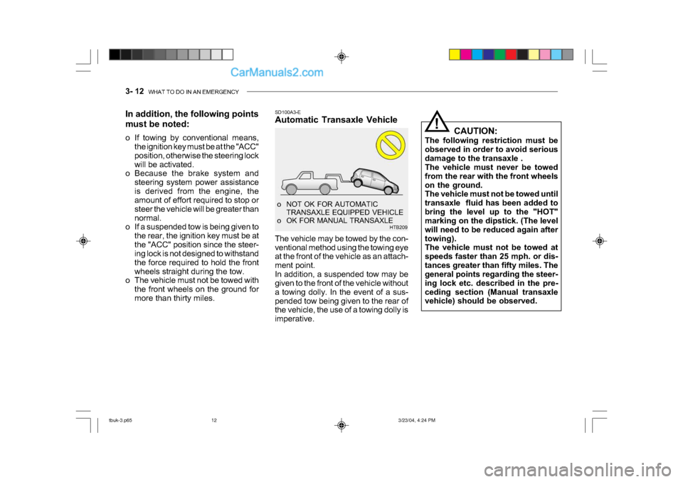
SD100A3-E
Automatic Transaxle Vehicle
The vehicle may be towed by the con-
ventional method using the towing eye
at the front of the vehicle as an attach-
ment point.
In addition, a suspended tow may be
given to the front of the vehicle without
a towing dolly. In the event of a sus-
pended tow being given to the rear of
the vehicle, the use of a towing dolly is
imperative.
o NOT OK FOR AUTOMATIC
TRANSAXLE EQUIPPED VEHICLE
o OK FOR MANUAL TRANSAXLE HTB209
In addition, the following points
must be noted:
o If towing by conventional means,
the ignition key must be at the "ACC"
position, otherwise the steering lock
will be activated.
o Because the brake system and
steering system power assistance
is derived from the engine, the
amount of effort required to stop or
steer the vehicle will be greater than
normal.
o If a suspended tow is being given to
the rear, the ignition key must be at
the "ACC" position since the steer-
ing lock is not designed to withstand
the force required to hold the front
wheels straight during the tow.
o The vehicle must not be towed with
the front wheels on the ground for
more than thirty miles.
tbuk-3.p65 3/23/04, 4:24 PM
12
Page 376 of 445

WHAT TO DO IN AN EMERGENCY 3- 13
D120A01A-EAT
IF YOU LOSE YOUR KEYS
Information about the key of immobi-
lizer system will be found on page 1-4.CAUTION:
If the car is being towed with all
four wheels on the ground, it can
be towed only from the front. Be
sure that the transaxle is in neu-
tral. Do not tow at speeds greater
than 30 mph (50 km/h) and for more
than 15 miles(25 km).
Be sure the steering is unlocked by
placing the key in the "ACC" posi-
tion. A driver must be in the towed
vehicle to operate the steering and
brakes.
!
(3)Attach a tow cable, chain or strap to
the towing hook on the front bumper.
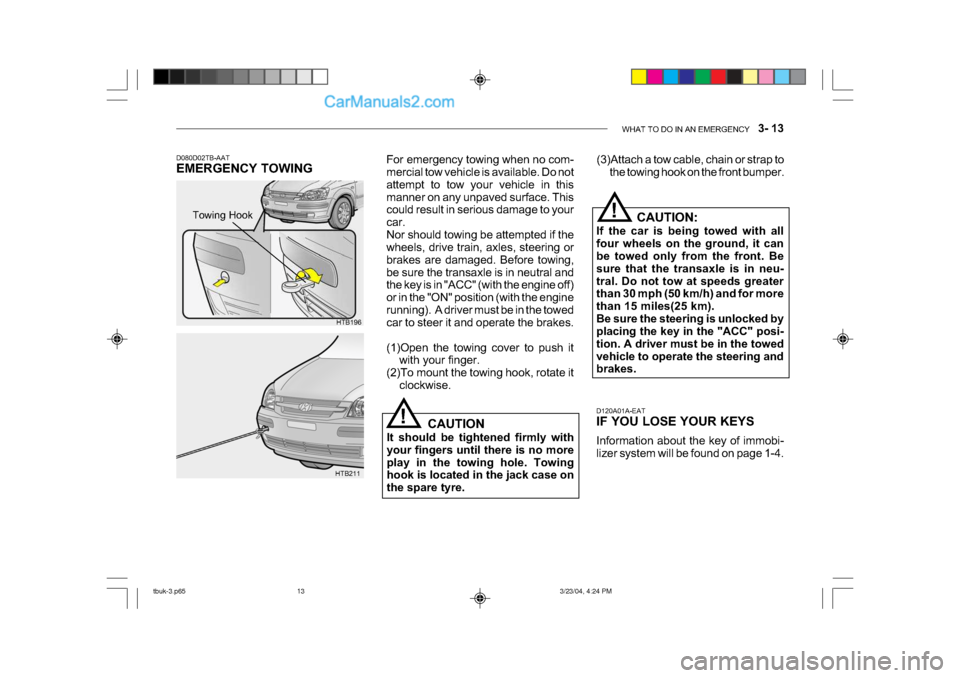
D080D02TB-AAT
EMERGENCY TOWING For emergency towing when no com-
mercial tow vehicle is available. Do not
attempt to tow your vehicle in this
manner on any unpaved surface. This
could result in serious damage to your
car.
Nor should towing be attempted if the
wheels, drive train, axles, steering or
brakes are damaged. Before towing,
be sure the transaxle is in neutral and
the key is in "ACC" (with the engine off)
or in the "ON" position (with the engine
running). A driver must be in the towed
car to steer it and operate the brakes.
(1)Open the towing cover to push it
with your finger.
(2)To mount the towing hook, rotate it clockwise.
HTB196
HTB211 CAUTION
It should be tightened firmly with
your fingers until there is no more
play in the towing hole. Towing
hook is located in the jack case on
the spare tyre.
!
Towing Hook
tbuk-3.p65
3/23/04, 4:24 PM
13
Page 418 of 445

DO-IT-YOURSELF MAINTENANCE 6- 27
!
5. Open the bonnet.
6. Draw the vertical line (through the
center of each headlight beam pat-
tern) and the horizontal line (through
the center of each headlight beam
pattern) on the aiming screen.
And then, draw the horizontal paral-
lel line at 1.18 in. (30 mm ) under the
horizontal line.
7. Adjust each cut-off line of the low beam to the parallel line with a phillips
screwdriver - VERTICAL AIMING.
8. Adjust each cut-off line of the low
beam to each vertical line with a
phillips screwdriver - HORIZONTAL
AIMING. HTB269
Horizontal Aiming
Vertical
Aiming
G290A01FC-EAT
HEADLIGHT AIMING ADJUST-
MENT
Before performing aiming adjustment,
make sure of the following.
1. Keep all tires inflated to the correct pressure.
2. Place the vehicle on level ground
and press the front bumper and rear
bumper down several times. Place
the vehicle at a distance of 118 in.
(3,000 mm) from the test wall.
3. See that the vehicle is unloaded (except for full levels of coolant,
engine oil and fuel, and spare tire,
jack, and tools).
4. Clean the head lights lens and turn
on the headlight (low beam). WARNING:
Be sure to carefully wipe away any
water drained out in this manner,
because the fuel mixed in the water
might be ignited and result in a fire.
1. Remove the engine cover.
2. Disconnect the air intake hose from air cleaner cover.
3. Loosen the drain plug at the bottom
of the fuel filter.
4. Tighten the drain plug when water no longer comes out.
5. Check to be sure that the warning lamp illuminates when the ignition
key is turned to "ON", and that it
goes off when the engine is started.
If in doubt, consult your nearest au-
thorized HYUNDAI dealer.
G300B01FC
tbuk-6.p65 3/23/04, 4:27 PM
27
Page 443 of 445

INDEX 10- 3
ENGINE OIL REPLENISHMENT ................................ 6-8
ENGINE OIL ................................................... ............ 6-6
F
FRONT ASHTRAY ... ................................................. 1-54
FRONT SEAT ................................................... ........1-11
FRONT FOG LIGHT SWITCH.................................. 1-52
FUEL ECONOMY ........ ............................................... 2-7
FUEL GAUGE ................................................... ........1-43
FUEL RECOMMENDATIONS ..................................... 1-1
FUSE PANEL DESCRI PTION.................................. 6-34
FUSIBLE LINKS ................................................... .....6-24
G
GLOVE BOX ................................................... ..........1-59
H
HAZARD WARNING SYSTEM .................................1-51
HEADLIGHT AIMING ADJUSTEMENT ....................6-27
HEADLIGHT BULB ................................................... 6-28
HEADLIGHT LEVELING DEVICE SYSTEM.............1-55
HEAD RESTRAINT ADJUSTMENT.......................... 1-14
HEATED REAR WINDOW ........................................1-52
HEATING AND COOLING CONTROL .....................1-71
HEIGHT ADJUSTABLE FRONT SEAT SHOULDER BELT ................................................ 1-19
HORN ................................................... .....................1-70
HOW TO USE LUGGAGE ROO M ............................1-66I
IF THE ENGINE CANNOT BE CRANKED
................. 3-2
IF THE ENGINE OVERHEATS ................................... 3-4
IF THE ENGINE WILL NOT START ........................... 3-2
IF THE EVENT OF A PUNCTURE ............................. 3-6
IMMOBILISER SYSTEM ............................................. 1-4
INDIVIDUAL CI RCUIT FUSES ................................. 6-24
INSTRUMENT CLUSTER AND INDICATORS .........1-37
INTERIOR LIGHT ................................................... ..1-58
INTERIOR REAR VIEW MIRROR ............................1-61
J
JUMP STARTING ..... .................................................. 3 -3
K
KEY POSITIONS ................................................... ..... 2-3
L
LIGHTING SWITCH .................................................. 1-49
LUGGAGE BOARD ...................................... .............1-67
LUGGAGE NET ................................................... .....1-67
LUGGAGE ROOM ................................................... .1-66
LUGGAGE UNDER TRAY........................................ 1-66
LUMBAR SUPPORT ADJUSTMENT........................ 1-13
tbuk-10.p65 3/23/04, 4:31 PM
3