2004 Hyundai Coupe coolant
[x] Cancel search: coolantPage 331 of 389
6
OWNER MAINTENANCE
5ENGINE OIL
SG030A1-E The correct engine oil level is of para-
mount importance. An excessively high or low oil level may result inirreparable damage being sustained by the engine. The engine oil level must be checked on a daily basis orwhenever the vehicle is refuelled, whichever occurs sooner.
In addition, it is imperative that only
an approved grade and specificationof oil is used to avoid the possibility of serious engine damage and prema-ture wear. The use of "budget price" oil is a false economy that must be avoided if the maximum reliability anduseful life is to be obtained from the vehicle.
SG020B1-E The following items should be checked on a daily basis or whenever the vehicle is refuelled, whichever occurssooner.
o Engine oil level.
o Engine coolant level.
o Power steering fluid level.
o Brake fluid level.
o Windscreen washer fluid level.
o Battery condition.
o Tyre condition and pressures.
o Operation and cleanliness of all lighting equip-ment.
o Windscreen wiper and washer op-
eration.
o Horn operation.
o Warning lamp operation.
o Adjustment and cleanliness of mir- rors.
o Seat and seat belt adjustment and operation.
o Fluid leakage.
The vehicle must not be driven if the daily operating checks indicate that any item of equipment related to the safety or roadworthiness of the ve-hicle is not functioning correctly. DAILY OPERATING CHECKS
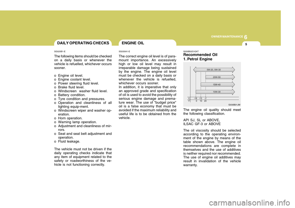
G030B02O-EAT Recommended Oil
1. Petrol Engine The engine oil quality should meet the following classification. API SJ, SL or ABOVE, ILSAC GF-3 or ABOVE The oil viscosity should be selected according to the operating environ- ment of the engine by means of thetable shown above. The engine oil recommendations are complete in themselves and the use of additivesis neither required nor recommended. The use of engine oil additives may result in invalidation of the vehiclewarranty.
G030B01JM
Page 336 of 389
6OWNER MAINTENANCE
10
SG050B1-E
Coolant recommendations
Only ethylene glycol based coolant with a corrosion inhibitor suited to aluminium alloy engine components should be used in the cooling system.No further additives or inhibitors should be used. The coolant specific gravity should be checked as pre-scribed in the maintenance schedule to ensure adequate frost and corro- sion protection. In addition, the en-gine coolant must be replaced at the specified interval since the corrosion inhibitor properties deteriorate withtime.It is important to note that whilst anincrease in the concentration of anti freeze gives an increase in the level of frost protection, a solution which isin excess of 65% anti freeze will result in reduced frost protection and engine overheating. Therefore therecommended concentration of 50% should not be exceeded for general use. The use of methanol based anti freeze compounds may result in engine over- heating and will invalidate the vehiclewarranty.
!
ENGINE COOLANT CHECK- ING AND REPLACING
SG050A1-E
WARNING:
Do not remove the radiator cap
when the engine is hot, since the system is pressurized and coolant may be ejected from the radiator resulting in scalding. NOTE: It is imperative that vehicles fitted
with an air conditioning system have a coolant concentration of the recommended strength at all times. The use of the air condition-ing system when the cooling sys- tem is filled with water only will result in the heater matrix freezingand subsequently bursting.
Page 337 of 389
6
OWNER MAINTENANCE
11
HGK4006
SG050C1-E
Engine Coolant Level
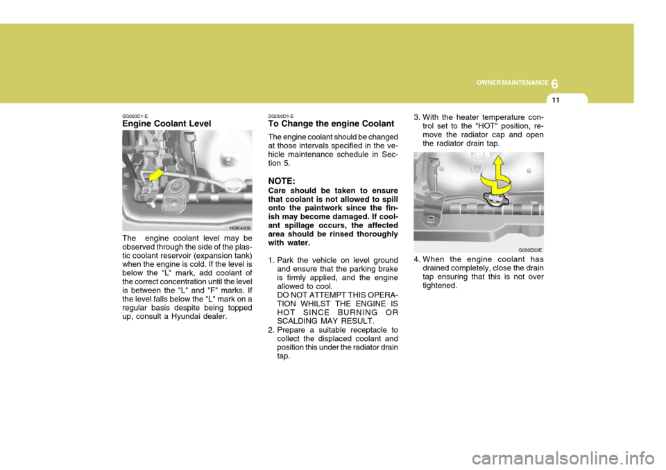
The engine coolant level may be
observed through the side of the plas- tic coolant reservoir (expansion tank) when the engine is cold. If the level is below the "L" mark, add coolant ofthe correct concentration until the level is between the "L" and "F" marks. If the level falls below the "L" mark on aregular basis despite being topped up, consult a Hyundai dealer. SG050D1-E
To Change the engine Coolant
The engine coolant should be changed at those intervals specified in the ve- hicle maintenance schedule in Sec- tion 5. NOTE: Care should be taken to ensure that coolant is not allowed to spill onto the paintwork since the fin- ish may become damaged. If cool-ant spillage occurs, the affected area should be rinsed thoroughly with water.
1. Park the vehicle on level ground and ensure that the parking brake is firmly applied, and the engine allowed to cool.DO NOT ATTEMPT THIS OPERA-TION WHILST THE ENGINE ISHOT SINCE BURNING OR SCALDING MAY RESULT.
2. Prepare a suitable receptacle to collect the displaced coolant andposition this under the radiator drain tap. 4. When the engine coolant has
drained completely, close the drain tap ensuring that this is not over tightened. G050D03E
3. With the heater temperature con-
trol set to the "HOT" position, re-move the radiator cap and open the radiator drain tap.
Page 338 of 389

6OWNER MAINTENANCE
12
G050D04E
SPARK PLUGS
G060A01GK-EAT Your engine was originally equipped with platinum-tipped or iridium-tipped spark plugs (2.7L only).Platinum-tipped or iridium-tipped sparkplugs will last longer than conven-tional type spark plugs. Platinum- tipped spark plug can be identified by blue lines on the ceramic shell. NOTE: Do not clean or regap platinum- tipped/iridium-tipped spark plugs.
0.039 ~ 0.043 in. (1.0~1.1 mm)
!WARNING:
The cooling fan is controlled by engine coolant temperature and may sometimes operate even whenthe engine is not running. Use extreme caution when working near the blades of the cooling fan sothat you are not injured by a rotat- ing fan blade. As the engine cool- ant temperature decreases, the fanwill automatically shut off. This is a normal condition.
5. Prepare a suitable quantity of new
engine coolant (refer to section 9) and pour this into the radiator.
HSM392
1.6L/2.0L 2.7L
0.039 ~ 0.043 in. (1.0~1.1 mm)
6. Start the engine with the radiator
cap still removed and continue to add coolant as the level decreases as air is expelled from the system.When the level remains constant, replace the radiator cap and re- plenish the coolant reservoir.
7. When the engine is hot, check to ensure that no coolant leaks arepresent.
Page 344 of 389
6OWNER MAINTENANCE
18MANUAL TRANSAXLE LUBRICANT
HGK5009
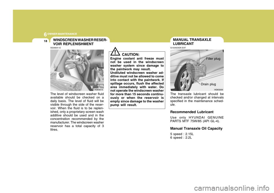
G100A03GK-EAT The transaxle lubricant should be
checked and/or changed at intervals specified in the maintenance sched-ule. Recommended Lubricant
Use only HYUNDAI GENUINE
PARTS MTF 75W/85 (API GL-4). Manual Transaxle Oil Capacity
5 speed : 2.15L 6 speed : 2.2L Drain plugSG090A1-E The level of windscreen washer fluid available should be checked on a daily basis. The level of fluid will bevisible through the side of the reser- voir. When the fluid is to be replen- ished, only a proprietary screen washadditive should be used and in the concentration recommended by the manufacturer. The windscreen washerreservoir has a total capacity of 3 litres. CAUTION:
Engine coolant anti freeze mustnot be used in the windscreen washer system since damage tothe paintwork may result.Undiluted windscreen washer ad-ditive must not be allowed to come into contact with the paintwork. If spillage occurs, flush the affectedarea immediately with water. Do not operate the windscreen washer for more than 15 seconds continu-ously or when the reservoir is empty since damage to the washer pump will result.
WINDSCREEN WASHER RESER- VOIR REPLENISHMENT
!
HGK5014
Filler plug
Page 356 of 389
6OWNER MAINTENANCE
30
o If battery electrolyte is spilled onto
skin or into eyes, the effected area must be flushed with copious amounts of water and medical assis-tance sought.
o If battery electrolyte is ingested, copious amounts of water or milkfollowed by an ant-acid (raw egg ormilk of magnesia) must be drunk. Vomiting should not be induced and medical assistance must besought.
o Batteries must only be charged in well venti-lated areas from which naked lights or sources of sparks are excluded.
o Ensure that children, pets or other unautho-rized persons are keptaway from batteries.
o Do not allow anything to bridge the
positive (+) and negative (-) termi-nals of the battery.
o Never invert the battery.
The battery fitted during production isof the "Maintenance Free" type.
ELECTRIC COOLING FANS
!
YG210A1-E
WARNING:
The cooling fan is controlled by engine coolant temperature and may sometimes operate even whenthe engine is not running. Do not touch the radiator fan until it is completely stopped.As the coolant temperature de-creases the fan will automaticallyshut off. This is a normal condi- tion.
Checking Engine Cooling Fan The engine cooling fan should auto- matically come on if the engine cool-ant temperature is high.
Checking Condenser Cooling Fan The condenser cooling fan (in front of the condenser) should come on auto- matically whenever the air conditioneris in operation.
POWER STEERING HOSES
YG220A1-E It is suggested that you check the power steering hose connections for fluid leakage at those intervals speci- fied in the vehicle maintenance sched-ule in Section 5. The power steering hoses should be replaced if there are severe surface cracking, pulling, scuff-ing or worn spots. Deterioration of the hoses could cause premature failure. NOTE: The power steering pump may be noisy when the engine is firststarted in the extreme cold (-4°F). This noise is not abnormal and will stop as the engine warms up.If the power steering pump contin- ues to be noisy after the engine has warmed up, have it inspectedby your Authorized Hyundai Dealer.
Page 358 of 389
6OWNER MAINTENANCE
32
G290B01GK-EAT
Adjustment After Headlight As- sembly Replacement
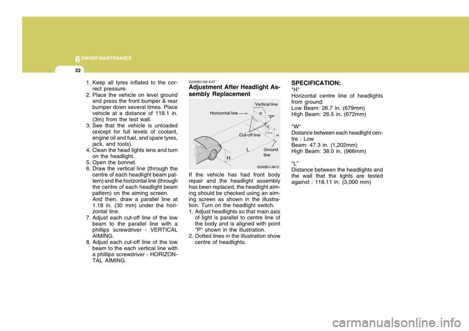
If the vehicle has had front body
repair and the headlight assembly has been replaced, the headlight aim- ing should be checked using an aim-ing screen as shown in the illustra- tion. Turn on the headlight switch.
1. Adjust headlights so that main axis of light is parallel to centre line of the body and is aligned with point"P" shown in the illustration.
2. Dotted lines in the illustration show centre of headlights. SPECIFICATION:
"H" Horizontal centre line of headlights from ground: Low Beam: 26.7 in. (679mm) High Beam: 26.5 in. (672mm) "W" Distance between each headlight cen- tre : Low Beam: 47.3 in. (1,202mm) High Beam: 38.0 in. (966mm) "L" Distance between the headlights and the wall that the lights are tested against : 118.11 in. (3,000 mm)
1. Keep all tyres inflated to the cor-
rect pressure.
2. Place the vehicle on level ground and press the front bumper & rearbumper down several times. Placevehicle at a distance of 118.1 in. (3m) from the test wall.
3. See that the vehicle is unloaded (except for full levels of coolant, engine oil and fuel, and spare tyres,jack, and tools).
4. Clean the head lights lens and turn on the headlight.
5. Open the bonnet.
6. Draw the vertical line (through the centre of each headlight beam pat- tern) and the horizontal line (through the centre of each headlight beampattern) on the aiming screen.And then, draw a parallel line at1.18 in. (30 mm) under the hori- zontal line.
7. Adjust each cut-off line of the low beam to the parallel line with aphillips screwdriver - VERTICAL AIMING.
8. Adjust each cut-off line of the low beam to the each vertical line witha phillips screwdriver - HORIZON- TAL AIMING. L
G290B01JM-D
W
H
H Cut-off line"P"
Vertical lineHorizontal line
Ground line
1.18 in.
Page 372 of 389
7EMISSION CONTROL SYSTEMS
2
SH010A1-E (Not all models) Depending upon the market for which the vehicle is destined, the emission control system will comprise one or more of the following emission controldevices.
(1) Crankcase emission control sys-
tem
(2) Evaporative emission control sys- tem
(3) Exhaust emission control systemIn order that the proper functioning of the emission control systems may be ensured, it is recommended that the vehicle is inspected and maintainedby an authorized Hyundai dealer in accordance with the maintenance schedule in this manual. EMISSION CONTROL SYS- TEMS
SH010B1-E
1. CRANKCASE EMISSION CON- TROL SYSTEM The positive crankcase ventilation system is employed to prevent air pollution caused by blow-by gases being emitted from the crankcase byintroducing fresh air to the crankcase through the air cleaner where this mixes with blow-by gases and thenpasses through the PCV valve into the intake manifold from where it sub- sequently enters the combustionchamber and is burned.
SH010C1-E
2. EVAPORATIVE EMISSION
CONTROL SYSTEM
The Evaporative Emission Control
System is designed to prevent fuelvapours from escaping into the atmo-sphere through the fuel tank ventila- tion system. SH010D1-E
3. EXHAUST EMISSION
CONTROL SYSTEM
The exhaust emission control system
is a highly effective system which controls exhaust emission while main- taining good vehicle performance. Whilst the engine is not running, fuel vapours generated inside the fuel tankare absorbed and stored in a char- coal canister. When the engine is started, the vapours stored in thecanister are drawn into the induction system through the purge control so- lenoid valve and are subsequentlyburned.The purge control solenoid valve iscontrolled by the ECU; when the en-gine coolant temperature is low or the engine is idling, the purge control valve is closed and fuel vapours re-main stored in the canister. Under normal running conditions when the engine is warm, the valve opens andthe vapours are drawn into the inlet tract and subsequently burned in the combustion chamber.