2004 Hyundai Coupe coolant
[x] Cancel search: coolantPage 158 of 389

EMISSION CONTROL SYSTEMS 7-1
7. EMISSION
CONTROL SYSTEMS
H010B01F-GAT
1. Crankcase Emission Control Sys-
tem
The positive crankcase ventilation system is
employed to prevent air pollution caused by H010A01A-GAT
EMISSION CONTROL SYSTEMS (If Installed)
Your Hyundai is equipped with an emission
control system to meet all requirements of the Emission prohibition rules of your province.
There are three emission control systems which
are as follows.
(1) Crankcase emission control system (2) Evaporative emission control system(3) Exhaust emission control system In order to assure the proper function of the
emission control systems, it is recommended that you have your car inspected and main-tained by an authorized Hyundai dealer in ac-cordance with the maintenance schedule in thismanual. H010C01F-GAT
2. Evaporative Emission Control Sys-
tem (If Installed)
The evaporative emission control system is
designed to prevent fuel vapors from escapinginto the atmosphere. Canister
While the engine is inoperative, fuel vapors
generated inside the fuel tank are absorbed and stored in the canister. When the engine is
running, the fuel vapors absorbed in the canis-ter are drawn into the induction system throughthe purge control solenoid valve. Purge Control Solenoid Valve
The purge control solenoid valve is controlled
by the ECM; when the engine coolant tempera- ture is low, and during idling, it closes, so that
evaporated fuel is not taken into the engine.After engine warm-up, during ordinary driving, itopens so as to introduce evaporated fuel to theengine. H010D01A-AAT
3. Exhaust Emission Control System
The exhaust emission control system is a high-
ly effective system which controls exhaust emis-sions while maintaining good vehicleperformace.
H020A01A-GAT
CATALYTIC CONVERTER (If Installed)
Catalytic Converter
SSA7020A
The catalytic converter is part of the exhaust
emission control system. Its purpose is to re- move certain engine emission products fromthe engine's exhaust. It looks something like amuffler and is located underneath the car in theexhaust system.
blow-by gases being emitted from the crank-
case. This system supplies fresh air to the
crankcase through the air cleaner. Inside thecrankcase, the fresh air mixes with blow-bygases, then passes through the PCV valve intothe induction system.
7
Page 165 of 389

VEHICLE SPECIFICATIONS 9-3
Oil & Grease Standard
1.6L / 2.7L API SG or SAE 20W-40, 20W-50 (ABOVE -10°C)
ABOVE SAE 15W-40, 15W-50 (ABOVE -15°C) SAE 10W-30 (-25°C ~ 40°C) SAE 10W-40, 10W-50 (ABOVE -25°C)SAE 5W-20 *1, *2 (BELOW -10°C) SAE 5W-30 *1 (BELOW 10°C) SAE 5W-40 *1 (BELOW 20°C)
2.0L API SH or SAE 15W- 40 (ABOVE -10°C)
ABOVE, SAE 10W-30 (-25°C ~ 40°C)
ILSAC GF-1 SAE 10W-40 (ABOVE -25°C)
or ABOVE SAE 5W-20 (BELOW -10°C) *1, *2
SAE 5W-30 (BELOW 10°C) *1SAE 5W-40 (BELOW 20°C) *1
*1. Restricted to driving condition and vehicle destination*2. Not recommended for sustained high speed vehicle operationNormal driving condition Severe driving condition HYUNDAI GENUINE PARTS MTF 75W/90 (API GL-4)DIAMOND ATF SP- III or SK ATF SP- III
PSF-3DOT 3 or DOT 4 equivalent Ethylene glycol base for aluminium radiator
J080A03GK-GAT
LUBRICATION CHART
Item
Engine Oil Engine Oil Consumption TransaxlePower Steering Brake Fluid CoolantQ'ty (liter) (us.qts., Imp.qts.)
Engine Oil: 1.6 L : 3.3 (3.5, 2.9)2.0 L : 3.85 (4.07, 3.39) 2.7 L : 4.5 (4.76, 4.0) Oil Pan: 1.6 L : 3.0 (3.17, 2.64) (MAX)
2.0 (2.11, 1.76) (MIN)
2.0 L : 3.55 (3.75, 3.12) (MAX) 2.6 (2.75, 3.3) (MIN)
2.7 L : 4.2 (4.44, 3.7) (MAX) 3.4 (3.59, 3) (MIN)
Oil Filter : 0.3 (0.32, 0.26) MAX. 1L / 1500 Km MAX. 1L / 1000 Km5 speed:2.15(2.27, 1.86) 6 speed:2.2(2.32, 1.94)
7.8 (8.2, 6.9) As requiredAs required 1.6L/2.0L : 7.0 (7.4, 6.2) 2.7L : 8.0 (8.5, 7.0)
Manual Auto
Page 167 of 389

INDEX
10-2
Driving
Economical driving ....................................................................... 2-11
Smooth cornering ......................................................................... 2-11
Winter driving ................................................................................ 2-11
E Emissions Control Systems ................................................................ 7-1
Engine Before starting the engine .............................................................. 2-2
Changing the oil and filter .............................................................. 6-6
Compartment .................................................................................. 6-1
Coolant ........................................................................................... 6-7
Coolant temperature gauge .......................................................... 1-29
If the engine overheats ................................................................... 3-2
Number ........................................................................................... 8-1
Oil .................................................................................................. 6-4 Oil consumption .............................................................................. 6-6
Starting ........................................................................................... 2-3
Engine Exhaust Can Be Dangerous ................................................... 2-1
FFog Li ght ........................................................................................... 1-43
Front Seats Adjustable front seats ..................................................................... 1-8
Adjustable headrests ...................................................................... 1-8Adjusting seat forward and rearward ............................................. 1-8
Adjusting seatback angle ...................... ......................................... 1-8
Lumbar support control ............... ................................................... 1-9
Seat cushion height adjustment ..................................................... 1-9
Seat warm er ................................................................................... 1-9
Fuel
Capacity .......................................................................................... 9-1
Gauge ........................................................................................... 1-28
Recommendations .......................................................................... 1-1 Fuel Filler Lid
Remote release ............................................................................ 1-45
Fuse Panel Description .......................................................... 6-23 ~ 6-24
Fuses ................................................................................................ 6-17
GGeneral Everyday Checks .................................................................. 6-4
Glove box .......................................................................................... 1-41
HHazard Warn ing System ................................................................... 1-36
Headlight Bulb ................................................................................... 6-20
Headlight Leveling Device System ................................................... 1-38
Heating and Cooling Control Rotary type ........................................................................ 1-51 ~ 1-56
Automatic type ................................................................... 1-57 ~ 1-62
High-mounted rear stoplight .............................................................. 1-44
Hood Release ................................................................................... 1-44
Horn ................................................................................................ 1-47
IIgnition Switch ..................................................................................... 2-2
Immobilizer System ............................................................................. 1-2
Infinity Sound System (B260) ........................................................... 1-80
Anti-Theft Device .......................................................................... 1-81
General operation ......................................................................... 1-81
Radio operation ............................................................................ 1-82
CD operation ................................................................................ 1-83
Instrument Cluster and Indicator ....................................................... 1-26
Instrument Panel Light Control (Rheostat) .......................................1-37
Instruments and Controls .................................................................. 1-25
Intermittent Wiper .............................................................................. 1-35
Page 183 of 389

1
CONTROLS AND EQUIPMENT
3RUNNING IN YOUR NEW HYUNDAI
B020A01S-EAT The longevity and performance of the vehicle are greatly affected by the care exercised during the first 1,000 miles of motoring. Because of modern manu-facturing techniques, rigid guidelines regarding maximum road speeds have become unnecessary. However, cer-tain precautions should be observed in order to obtain the best possible per- formance and useful life from the ve-hicle.
1) Do not race the engine without a
load (i.e revving the engine in neu- tral).
2) During the first 500 miles the maxi- mum engine speed should be re-stricted to 3,000 rpm and gradually increased thereafter.
3) Avoid prolonged constant speed operation. The internal componentsof the engine will become morequickly run in if the operation speed is varied during the running in pe- riod.
4) Never allow the engine to labour. Use the gearbox freely and avoidlarge throttle openings when theengine speed is below 1,500 rpm.BEFORE ENTERING THE VEHICLEAFTER ENTERING THE VEHICLE
YB020A1-E
o Ensure that all windows, mirrors
and lamps are clean.
o Check condition of all tyres.
o Ensure that no fluid leaks are evi-
dent.
o Ensure that the area around the vehicle is clear before driving off. YB020B1-E
o Ensure that all occupants fasten
and correctly adjust seat belts.
o Ensure that seat and headrestraint positions are adjusted for optimum safety, control and comfort.
o Adjust interior and exterior rear view mirrors.
o Verify correct operation of lamps, horn and other electrical equipment.
o Ensure that warning lamps illumi-
nate when ignition is turned on.
NOTE: Fluid levels such as engine oil, en- gine coolant, brake and windscreenwasher fluid should be checked daily or at each refuelling, which- ever occurs sooner.
Page 219 of 389

1
CONTROLS AND EQUIPMENT
39
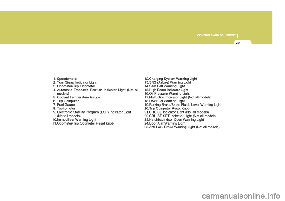
1. Speedometer
2. Turn Signal Indicator Light
3. Odometer/Trip Odometer
4. Automatic Transaxle Position Indicator Light (Not all models)
5. Coolant Temperature Gauge
6. Trip Computer
7. Fuel Gauge
8. Tachometer
9. Electronic Stability Program (ESP) Indicator Light (Not all models)
10.Immobiliser Warning Light
11.Odometer/Trip Odometer Reset Knob 12.Charging System Warning Light
13.SRS (Airbag) Warning Light
14.Seat Belt Warning Light
15.High Beam Indicator Light
16.Oil Pressure Warning Light
17.Malfuction Indicator Light (Not all models)
18.Low Fuel Warning Light
19.Parking Brake/Brake Fluide Level Warning Light
20.Trip Computer Reset Knob21.CRUISE Indicator Light (Not all models)
22.CRUISE SET Indicator Light (Not all models)
23.Hatchback door Open Warning Light
24.Door Ajar Warning Light
25.Anti-Lock Brake Warning Light (Not all models)
Page 224 of 389

1CONTROLS AND EQUIPMENT
44
!
INSTRUMENT CLUSTER
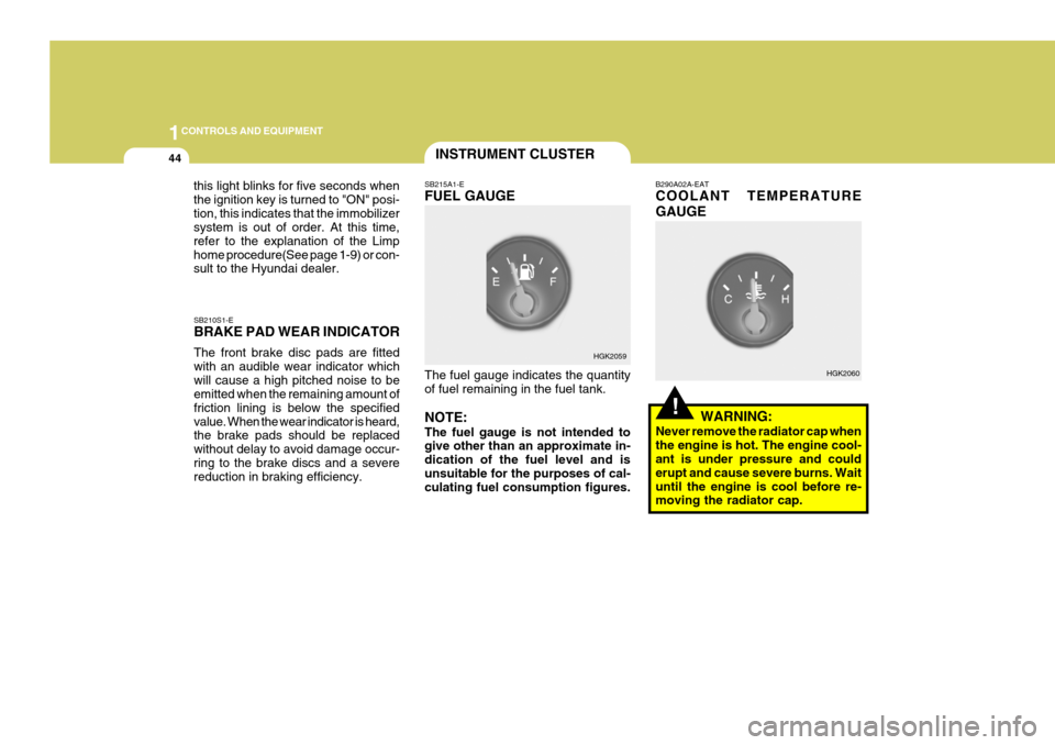
SB210S1-E BRAKE PAD WEAR INDICATOR The front brake disc pads are fitted with an audible wear indicator whichwill cause a high pitched noise to be emitted when the remaining amount of friction lining is below the specifiedvalue. When the wear indicator is heard, the brake pads should be replaced without delay to avoid damage occur-ring to the brake discs and a severe reduction in braking efficiency. SB215A1-E FUEL GAUGE The fuel gauge indicates the quantity of fuel remaining in the fuel tank. NOTE: The fuel gauge is not intended to give other than an approximate in- dication of the fuel level and isunsuitable for the purposes of cal- culating fuel consumption figures. B290A02A-EAT COOLANT TEMPERATURE GAUGE
WARNING:
Never remove the radiator cap when the engine is hot. The engine cool- ant is under pressure and could erupt and cause severe burns. Waituntil the engine is cool before re- moving the radiator cap.
HGK2059
HGK2060
this light blinks for five seconds when the ignition key is turned to "ON" posi-tion, this indicates that the immobilizer system is out of order. At this time, refer to the explanation of the Limphome procedure(See page 1-9) or con- sult to the Hyundai dealer.
Page 225 of 389

1
CONTROLS AND EQUIPMENT
45
!
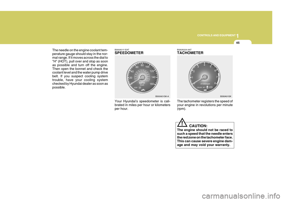
The needle on the engine coolant tem- perature gauge should stay in the nor-mal range. If it moves across the dial to "H" (HOT), pull over and stop as soon as possible and turn off the engine.Then open the bonnet and check the coolant level and the water pump drive belt. If you suspect cooling systemtrouble, have your cooling system checked by Hyundai dealer as soon as possible.
B300A01Y-EAT SPEEDOMETER Your Hyundai's speedometer is cali- brated in miles per hour or kilometers per hour.B330A02A-AAT TACHOMETER The tachometer registers the speed of your engine in revolutions per minute (rpm).
CAUTION:
The engine should not be raced tosuch a speed that the needle entersthe red zone on the tachometer face. This can cause severe engine dam- age and may void your warranty.
B300A01GK-A
B330A01GK
Page 295 of 389

2
DRIVING YOUR HYUNDAI
19
C190E01L
CAUTION:
o Never connect a trailer brake sys- tem directly to the vehicle brake system.
o When towing a trailer on steep grades (in excess of 12%) payclose attention to the engine cool-ant temperature gauge to ensure the engine does not overheat. If the needle of the coolant tem-perature gauge moves across the dial towards "H" (HOT), pull over and stop as soon as it is safe todo so, and allow the engine to idle until it cools down. You may proceed once the engine hascooled sufficiently.
! YC200D2-E Safety Cables Should the hitch connection between your car and the trailer or vehicle youare towing fail, the trailer or vehicle could wander dangerously across other lanes of traffic and ultimately leave theroadway. To eliminate this potentially dangerous situation, safety cables, at- tached between your car and the traileror towed vehicle, are required.
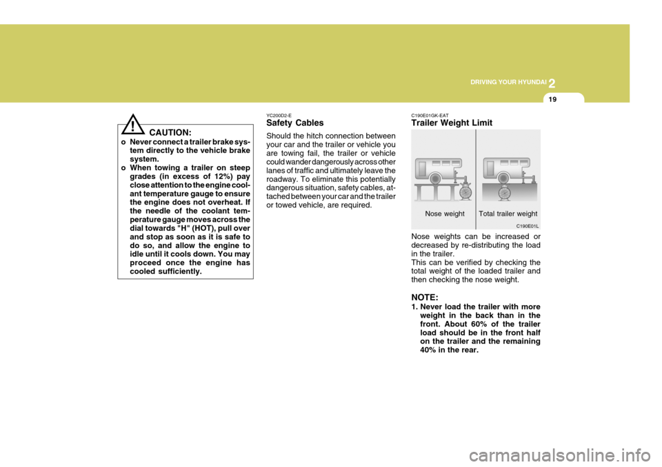
Nose weight Total trailer weight
C190E01GK-EAT Trailer Weight Limit Nose weights can be increased or decreased by re-distributing the load in the trailer.This can be verified by checking the total weight of the loaded trailer and then checking the nose weight. NOTE:
1. Never load the trailer with more
weight in the back than in the front. About 60% of the trailerload should be in the front half on the trailer and the remaining 40% in the rear.