2004 Hyundai Coupe steering belt
[x] Cancel search: steering beltPage 215 of 389

1
CONTROLS AND EQUIPMENT
35
B990B04Y-EAT Side Impact Airbag (Not all models)
B990B02Y-R
Your Hyundai is equipped with a side impact airbag in each front seat. Thepurpose of the airbag is to provide the vehicle's driver and/or the front pas- senger with additional protection thanthat offered by the seatbelt alone. The side impact airbags are designed to deploy only during certain side-impactcollisions, depending on the crash se- verity, angle, speed and point of im- pact. The side impact air bags are notdesigned to deploy in all side impact situations.
!WARNING:
o The side impact airbag is supple- mental to the driver's and the passenger's seat belt systems and is not a substitute for them. Therefore your seat belts mustbe worn at all times whilst the vehicle is in motion. The airbags deploy only in certain side im-pact conditions severe enough to cause significant injury to the vehicle occupants.
o For best protection from the side
impact airbag system and toavoid being injured by the de- ploying side impact airbag, both front seat occupants should sitin an upright position with the seat belt properly fastened. The driver's hands should be placedon the steering wheel at the 9:00 and 3:00 o'clock positions. The passenger's arms and handsshould be placed on their laps. o Do not use any accessory seat
covers.
o Use of seat covers could prevent
or reduce the effectiveness of the system.
o Do not install any accessories on
the side or near the side impactairbag.
o Do not use excessive force on the side of the seat.
o Do not place any objects over the
airbag or between the airbag and yourself.
o Do not place any objects (an
umbrella, bag, etc.) between the front door and the front seat. Such objects may become dan-gerous projectiles and cause in- jury if the supplemental side im- pact air bag inflates.
o To prevent unexpected deploy- ment of the side impact air bagthat may result in personalinjury,avoid impact to the side airbag sensor when the ignition key is on.
Page 279 of 389
2
DRIVING YOUR HYUNDAI
3TO START THE ENGINEBEFORE STARTING THE EN- GINE
SC030A1-E Before you start the engine, you should always:
1. Look around the vehicle to be sure
there are no flat tires, puddles of oil or water or other indications of pos- sible trouble.
2. After entering the car, check to be sure the parking brake is engaged.
3. Check that all windows, and lights
are clean.
4. Check that the interior and exterior mirrors are clean and in position.
5. Check your seat, seatback and head restraint to be sure they are intheir proper positions.
6. Close all the doors.
7. Fasten your seat belt and be sure that all other occupants have fas-tened theirs.
8. Turn off all lights and accessories that are not needed.
9. When you turn the ignition switch to "ON' check that all appropriate warning lights are operating and that you have sufficient fuel.
10.Check the operation of warning lights and all bulbs when key is inthe "ON" position. SC040A1-F COMBINATION IGNITION SWITCH AND STEERING LOCK
o If your Hyundai is equipped with a
manual transaxle, place the shift lever in neutral and depress the clutch pedal fully.
o If your Hyundai has an automatic
transaxle, place the shift lever in "P"(park).
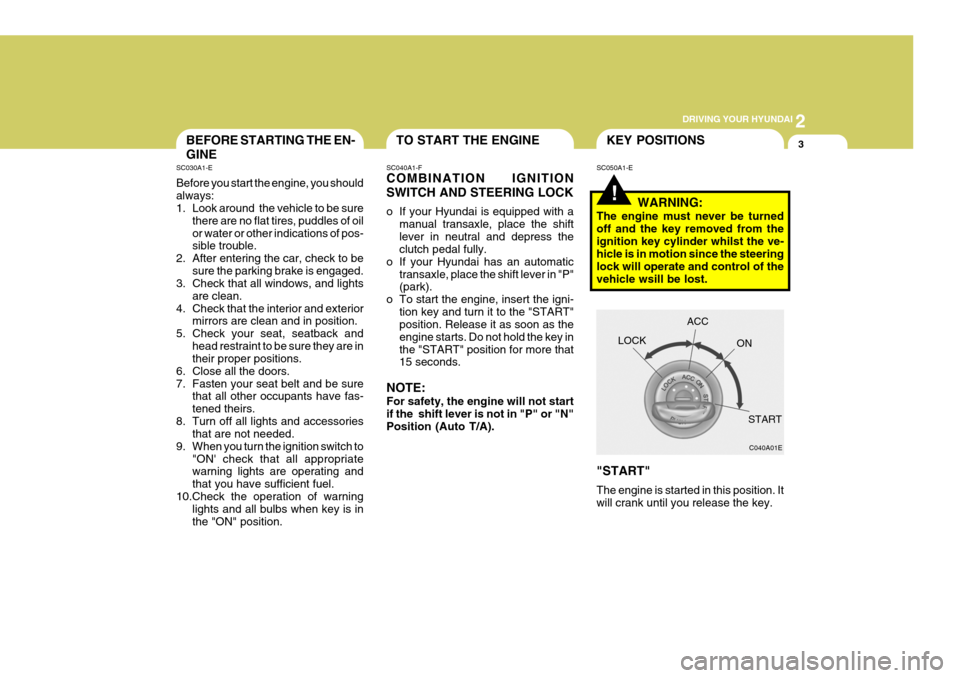
o To start the engine, insert the igni- tion key and turn it to the "START"position. Release it as soon as the engine starts. Do not hold the key inthe "START" position for more that 15 seconds.
NOTE: For safety, the engine will not start if the shift lever is not in "P" or "N" Position (Auto T/A).
!
SC050A1-E KEY POSITIONS
WARNING:
The engine must never be turned off and the key removed from theignition key cylinder whilst the ve- hicle is in motion since the steering lock will operate and control of thevehicle wsill be lost. "START" The engine is started in this position. It will crank until you release the key. LOCK
C040A01E
ACC
ON
START
Page 322 of 389

5VEHICLE MAINTENANCE REQUIREMENTS
6
ENGINE OIL AND FILTER AIR CLEANER FILTER SPARK PLUGS TIMING BELT BRAKE PADS, CALIPERS AND ROTORS REAR BRAKE DRUMS/LININGS, PARKING BRAKE STEERING GEAR BOX, LINKAGE & BOOTS/ LOWER ARM BALL JOINT DRIVESHAFTS & BOOTS MANUAL TRANSAXLE OIL AUTOMATIC TRANSAXLE FLUID POLLEN FILTER(FOR BLOWER UNIT)
F040A04GK-EAT The following items must be serviced more frequently on cars normally used under severe driving conditions. Refer to the chart below for the appropriate maintenance intervals. R : Replace I : Inspect and, after inspection, clean, adjust, repair or replace if necessaryMAINTENANCE UNDER SEVERE USAGE CONDITIONS
MAINTENANCE INTERVALS
A, B, C, D, E, F, G, H, I, K C, E B, H D, E, F, G C, D, G, H C, D, G, H C, D, E, F C, D, E, F, G A, C, D, E, F, G, H, I, J A, C, E, F, G, H, I C, E
MAINTENANCE ITEMDRIVING
CONDITION
EVERY 4,500MILES OR 6 MONTHS MORE FREQUENTLY MORE FREQUENTLY EVERY 37,000MILES OR 48MONTHS MORE FREQUENTLY MORE FREQUENTLY MORE FREQUENTLYEVERY 9,000MILES OR 12 MONTHS EVERY 60,000MILES EVERY 27,000MILES MORE FREQUENTLY
R R R R II II
R R R
MAINTENANCE
OPERATION
SEVERE DRIVING CONDITIONS
A - Repeatly driving short distance of less than 5miles(8km) in normal temperature or less than 10miles(16km) in freezing temperature
B - Extensive engine idling or low speed driving for long distances
C - Driving on rough, dusty, muddy, unpaved, graveled or salt- spread roads
D - Driving in areas using salt or other corrosive materials or in very cold weather E - Driving in sandy areas
F - Driving in heavy traffic area over 90°F(32°C)G - Driving on uphill, downhill, or mountain roadH - Towing a Trailer, or using a camper, or roof rack
I - Driving as a patrol car, taxi, other commercial use or vehicle towing
J - Driving over 100 MPH(170 Km/h) K - Frequently driving in stop-and-go conditions
Page 326 of 389
5VEHICLE MAINTENANCE REQUIREMENTS
10
6ZF070M1-A
o Steering gear box, linkage &boots/lower arm ball joint
With the vehicle stopped and engine off, check for excessive freeplay in the steering wheel. Check the linkage for bends or dam- age. Check the dust boots and ball joints for deterioration, cracks, or dam- age. Replace any damaged parts. 6ZF070N1-A
o Power steering pump, belt and hoses
Check the power steering pump and hoses for leakage and damage. Re- place any damaged or leaking partsimmediately. Inspect the power steer- ing belt for evidence of cuts, cracks, excessive wear, oiliness and propertension. Replace or adjust it if neces- sary. 6ZF070P1-A
o Drive shafts and boots
Check the drive shafts, boots and
clamps for cracks, deterioration, ordamage. Replace any damaged parts and, if necessary, repack the grease.
6ZF070Q1-A
o Air conditioning refrigerant
Check the air conditioning lines and
connections for leakage and damage. Check air conditioning performance according to the relevant shop manualif necessary.
Page 327 of 389

6
Engine Compartment ................................................... 6-2
Daily Operating Checks ............................................... 6-5
Engine Oil .................................................................... 6-5
Engine Oil and Filter Replacement ............................. 6-8
Engine Coolant Checking and Replacing .................6-10
Spark Plugs ................................................................ 6-12
Changing the Air Cleaner Filter ................................ 6-15
Manual Transaxle Lubricant ...................................... 6-18
Automatic Transaxle Lubricant .................................. 6-19
Brake System Checking ............................................ 6-21
Air Conditioning System Maintenance ...................... 6-23
Changing the Pollen Filter ......................................... 6-25
Checking Engine Drive Belts ..................................... 6-27
Fusible Links .............................................................. 6-28
Battery Maintenance .................................................. 6-29
Power Steering Hoses ............................................... 6-30
Headlight Aiming Adjustment .................................... 6-31
Replacing Light Bulbs ................................................ 6-33
Bulb Wattage ............................................................. 6-40
Fuse Panel Description ............................................. 6-41
OWNER MAINTENANCE
6
Page 331 of 389
6
OWNER MAINTENANCE
5ENGINE OIL
SG030A1-E The correct engine oil level is of para-
mount importance. An excessively high or low oil level may result inirreparable damage being sustained by the engine. The engine oil level must be checked on a daily basis orwhenever the vehicle is refuelled, whichever occurs sooner.
In addition, it is imperative that only
an approved grade and specificationof oil is used to avoid the possibility of serious engine damage and prema-ture wear. The use of "budget price" oil is a false economy that must be avoided if the maximum reliability anduseful life is to be obtained from the vehicle.
SG020B1-E The following items should be checked on a daily basis or whenever the vehicle is refuelled, whichever occurssooner.
o Engine oil level.
o Engine coolant level.
o Power steering fluid level.
o Brake fluid level.
o Windscreen washer fluid level.
o Battery condition.
o Tyre condition and pressures.
o Operation and cleanliness of all lighting equip-ment.
o Windscreen wiper and washer op-
eration.
o Horn operation.
o Warning lamp operation.
o Adjustment and cleanliness of mir- rors.
o Seat and seat belt adjustment and operation.
o Fluid leakage.
The vehicle must not be driven if the daily operating checks indicate that any item of equipment related to the safety or roadworthiness of the ve-hicle is not functioning correctly. DAILY OPERATING CHECKS
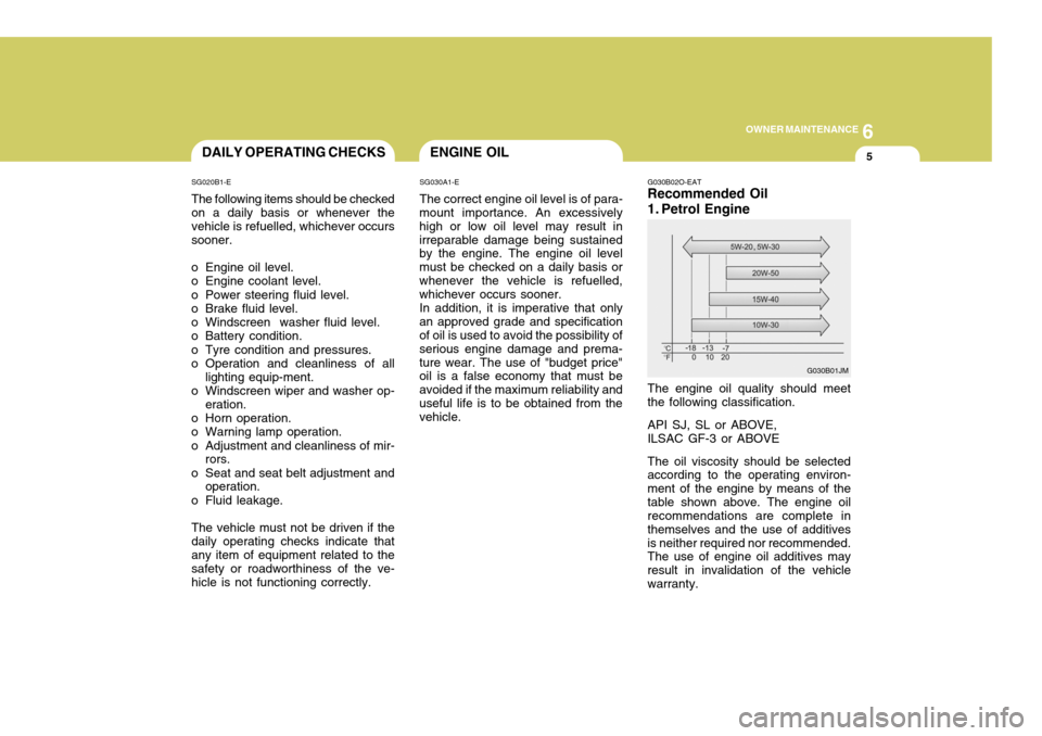
G030B02O-EAT Recommended Oil
1. Petrol Engine The engine oil quality should meet the following classification. API SJ, SL or ABOVE, ILSAC GF-3 or ABOVE The oil viscosity should be selected according to the operating environ- ment of the engine by means of thetable shown above. The engine oil recommendations are complete in themselves and the use of additivesis neither required nor recommended. The use of engine oil additives may result in invalidation of the vehiclewarranty.
G030B01JM
Page 350 of 389
6OWNER MAINTENANCE
24
SG140D1-E Off Season Maintenance The air conditioning must be run for ten minutes or so weekly during peri- ods when the system would not nor- mally be used to ensure that thecompressor and seals are lubricated. If this precaution is not observed the compressor seals may become stuckto the compressor shaft and dam- aged when the system is next used resulting in a loss of refrigerant anddamage to the compressor. SG140B1-E
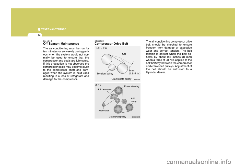
Compressor Drive Belt The air conditioning compressor drive
belt should be checked to ensurefreedom from damage or excessive wear and correct tension. The belt tension is correct when the belt de-flects by about 0.3 inches (8 mm) when a force of 98 N is applied to the belt halfway between the compressorand crankshaft pulleys. Adjustment of the belt should be entrusted to a Hyundai dealer.
Crankshaft pulley HTB219
A/C
Tension pulley 8mm (0.315 in.)
1.6L / 2.0L
G190A02B
A/C comp.
Crankshaft pulley
Power steering
Auto tensioner
Generator
2.7 L
Page 353 of 389
6
OWNER MAINTENANCE
27CHECKING BRAKE PEDAL CLEARANCE
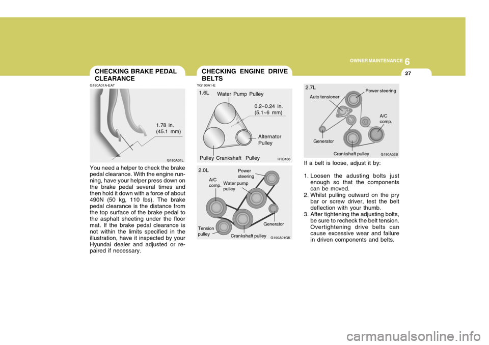
G180A01A-EAT You need a helper to check the brake pedal clearance. With the engine run- ning, have your helper press down onthe brake pedal several times and then hold it down with a force of about 490N (50 kg, 110 lbs). The brakepedal clearance is the distance from the top surface of the brake pedal to the asphalt sheeting under the floormat. If the brake pedal clearance is not within the limits specified in the illustration, have it inspected by yourHyundai dealer and adjusted or re- paired if necessary. 1.78 in.(45.1 mm)
YG190A1-E
CHECKING ENGINE DRIVE BELTS
If a belt is loose, adjust it by:
1. Loosen the adusting bolts justenough so that the components can be moved.
2. Whilst pulling outward on the pry bar or screw driver, test the beltdeflection with your thumb.
3. After tightening the adjusting bolts,
be sure to recheck the belt tension.Overtightening drive belts can cause excessive wear and failure in driven components and belts.
G180A01L
Tension pulleyGenerator
G190A01GK
Power steering
Water pump pulley
A/Ccomp.
2.0L G190A02B
A/C comp.
Crankshaft pulley
Power steering
Auto tensioner
Generator
2.7LWater Pump Pulley
Alternator Pulley
Pulley Crankshaft Pulley 0.2~0.24 in.(5.1~6 mm)
HTB186
1.6L
Crankshaft pulley