2004 Hyundai Coupe fuse
[x] Cancel search: fusePage 151 of 389

DO-IT-YOURSELF MAINTENANCE 6-19
CAUTION: A burned-out fuse indicates that there is a
problem in the electrical circuit. If you re- place a fuse and it blows as soon as theaccessory is turned on, the problem is seri-ous and should be referred to a Hyundaidealer for diagnosis and repair. Never re-place a fuse with anything except a fusewith the same or a lower amperage rating. Ahigher capacity fuse could cause damageand create a fire hazard.
NOTE: See page 6-23 for the fuse panel descrip-
tions.
Burned out
G200B03YGood G210A01A-AAT
CHECKING THE BATTERY
WARNING: Batteries can be dangerous! When working
with batteries, carefully observe the follow- ing precautions to avoid serious injuries.
The fluid in the battery contains a strong solu-
tion of sulfuric acid, which is poisonous andhighly corrosive. Be careful not to spill it onyourself or the car. If you do spill battery fluid onyourself, immediately do the following:
o If battery fluid is on your skin, flush the affected areas with water for at least 15 minutes and then seek medical assistance.
o If battery fluid is in your eyes, rinse out your eyes with water and get medical assistanceas soon as possible. While you are beingdriven to get medical assistance, continueto rinse your eyes by using a sponge or softcloth saturated with water.
o If you swallow battery fluid, drink a large quantity of water or milk followed by milk ofmagnesia, eat a raw egg or drink vegetableoil. Get medical assistance as soon aspossible.
While batteries are being charged (either by a
battery charger or by the vehicle's alternator),they produce explosive gases. Always observethese warnings to prevent injuries from occur-ring: G210B01A-AAT
Checking the Battery Keep the battery clean. Any evidence of corro-
sion around the battery posts or terminals shouldbe removed using a solution of household bak-ing soda and warm water. After the batteryterminals are dry, cover them with a light coat-ing of grease.
G220A01A-AAT
CHECKING ELECTRIC COOLING FANS WARNING: The cooling fan is controlled by engine cool-
ant temperature and may sometimes oper- ate even when the engine is not running.Use extreme caution when working near theblades of the coolant fan, so that you are notinjured by a rotating fan blade. As the cool-ant temperature decreases the fan will auto-matically shut off. This is a normal condi-tion.
G220B01A-AAT
Checking Engine Cooling Fan The engine coolant fan should come on auto-
matically if the engine coolant temperature ishigh.
o Charge batteries only in a well ventilated
area.
o Do not permit flames, sparks or smoking in the area.
o Keep children away from the area.
Page 156 of 389

DO-IT-YOURSELF MAINTENANCE
6-24
G200C01GK-GAT
FUSE PANEL DESCRIPTION Engine Compartment
HGK205-EPROTECTED COMPONENTS
Generator Generator Condenser Fan Radiator FanEngine Control, ECM. ATM ControlIgnition, Start RelayABSABS Blower InjectorO 2 Sensor, ECM
DRL
Front Fog Light TCM, ECM
Horn. A/ConditionerHead Light (High)Head Light (LOW)
FUSE RATING
120A50A30A 30A 30A30A30A30A30A 15A 10A15A15A10A15A 15A 15A
DESCRIPTION
BATTBATT
COND RADECU
IGN
ABS 1ABS 2
BLOWER INJ
SNSR DRL
F/FOG ECU
HORN,A/CON H/LP (H1)
H/LP (LO)
NOTE:
Not all fuse panel descriptions in this manual may be applicable to your vehicle. It is accurate at the time of printing. When you inspect the fuse
box on your vehicle, refer to the fuse box label.
If installed
Page 157 of 389

DO-IT-YOURSELF MAINTENANCE 6-25
DESCRIPTION
IG COIL
AMP
B/UP LAMP
A/BAG IND
A/BAG
HTD MIR HAZARD
R/WIPER TAIL-RH
F/WIPER
A/C SW
RR DEFOG STOP
TAIL-LH
A/CON ECU
CLUSTER
ROOM LP
P/WINDOW T/GATE
IGN
RR FOG C/LIGHT
S/ROOF S/HTR ABS
AUDIO
G200D01GK-GAT
Inner Panel
HGK204-E
PROTECTED COMPONENTS
Ignition Coil, ECM
AMP. Multi Gauge Unit B/Up LampAir Bag Indicator Air Bag Outside Mirror DefrosterHazard Warning Light Rear Window Wiper
Tail LightFront Window Wiper A/Conditioner Rear Window DefrosterStop Light
Tail Light A/Conditioner
ECM, Multi Gauge Unit, TCMCluster Map Light, Clock, Audio Power WindowTail Gate Open A/Con, A.Q.S Sensor Rear FogC/Lighter, Outside Mirror Sunroof Seat WarmerABS. TCS Audio, Clock
FUSERATING
20A20A 10A10A 15A 10A10A 15A 10A20A 10A 30A15A 10A 10A10A 10A 10A30A 15A 10A10A 15A 15A20A 10A 10A
Page 167 of 389

INDEX
10-2
Driving
Economical driving ....................................................................... 2-11
Smooth cornering ......................................................................... 2-11
Winter driving ................................................................................ 2-11
E Emissions Control Systems ................................................................ 7-1
Engine Before starting the engine .............................................................. 2-2
Changing the oil and filter .............................................................. 6-6
Compartment .................................................................................. 6-1
Coolant ........................................................................................... 6-7
Coolant temperature gauge .......................................................... 1-29
If the engine overheats ................................................................... 3-2
Number ........................................................................................... 8-1
Oil .................................................................................................. 6-4 Oil consumption .............................................................................. 6-6
Starting ........................................................................................... 2-3
Engine Exhaust Can Be Dangerous ................................................... 2-1
FFog Li ght ........................................................................................... 1-43
Front Seats Adjustable front seats ..................................................................... 1-8
Adjustable headrests ...................................................................... 1-8Adjusting seat forward and rearward ............................................. 1-8
Adjusting seatback angle ...................... ......................................... 1-8
Lumbar support control ............... ................................................... 1-9
Seat cushion height adjustment ..................................................... 1-9
Seat warm er ................................................................................... 1-9
Fuel
Capacity .......................................................................................... 9-1
Gauge ........................................................................................... 1-28
Recommendations .......................................................................... 1-1 Fuel Filler Lid
Remote release ............................................................................ 1-45
Fuse Panel Description .......................................................... 6-23 ~ 6-24
Fuses ................................................................................................ 6-17
GGeneral Everyday Checks .................................................................. 6-4
Glove box .......................................................................................... 1-41
HHazard Warn ing System ................................................................... 1-36
Headlight Bulb ................................................................................... 6-20
Headlight Leveling Device System ................................................... 1-38
Heating and Cooling Control Rotary type ........................................................................ 1-51 ~ 1-56
Automatic type ................................................................... 1-57 ~ 1-62
High-mounted rear stoplight .............................................................. 1-44
Hood Release ................................................................................... 1-44
Horn ................................................................................................ 1-47
IIgnition Switch ..................................................................................... 2-2
Immobilizer System ............................................................................. 1-2
Infinity Sound System (B260) ........................................................... 1-80
Anti-Theft Device .......................................................................... 1-81
General operation ......................................................................... 1-81
Radio operation ............................................................................ 1-82
CD operation ................................................................................ 1-83
Instrument Cluster and Indicator ....................................................... 1-26
Instrument Panel Light Control (Rheostat) .......................................1-37
Instruments and Controls .................................................................. 1-25
Intermittent Wiper .............................................................................. 1-35
Page 179 of 389

CAUTION:
When installing a container of liquid air freshener inside the vehicle, do not place it near the instrument cluster nor on the instrument panel surface. If there is any leakage from the air freshener onto these areas (Instrument cluster, instrument panel or air ventilator), it may damage these parts. If the liquid from the air freshener does leak onto these areas, wash themwith water immediately.!
1. Passenger's Drink Holder
2. Passenger's Side Air Bag (Not all models)
3. Multi Guage (Not all models)
4. Front Fog Light Switch (Not all models)
5. Rear Fog Light Switch
6. Digital Clock
7. Hazard Warning Switch
8. Front Seat warmer (Not all models)
9. Windscreen Wiper/Washer Switch
10. Steering Wheel Tilt Lever (Not all models)
11. Multi-Function Light
12. Panel Brightness Control Knob
(Rheostat Switch) (Not all models) 13. Electronic Stability Progrem (ESP) Switch
(Not all models)
14. Headlight Leveling Device
15. Centre Console
16. Glove Box
17. Parking Brake Lever
18. Shift Lever
19. Cigarette Lighter
20. Ashtray
21. Heating/Air Conditioning Control Panel
22. Horn and Driver's Airbag
23. Cruise Control Switch (Not all models)
24. Fuse Box Relay
25. Bonnet Release Lever
Page 214 of 389

1CONTROLS AND EQUIPMENT
34
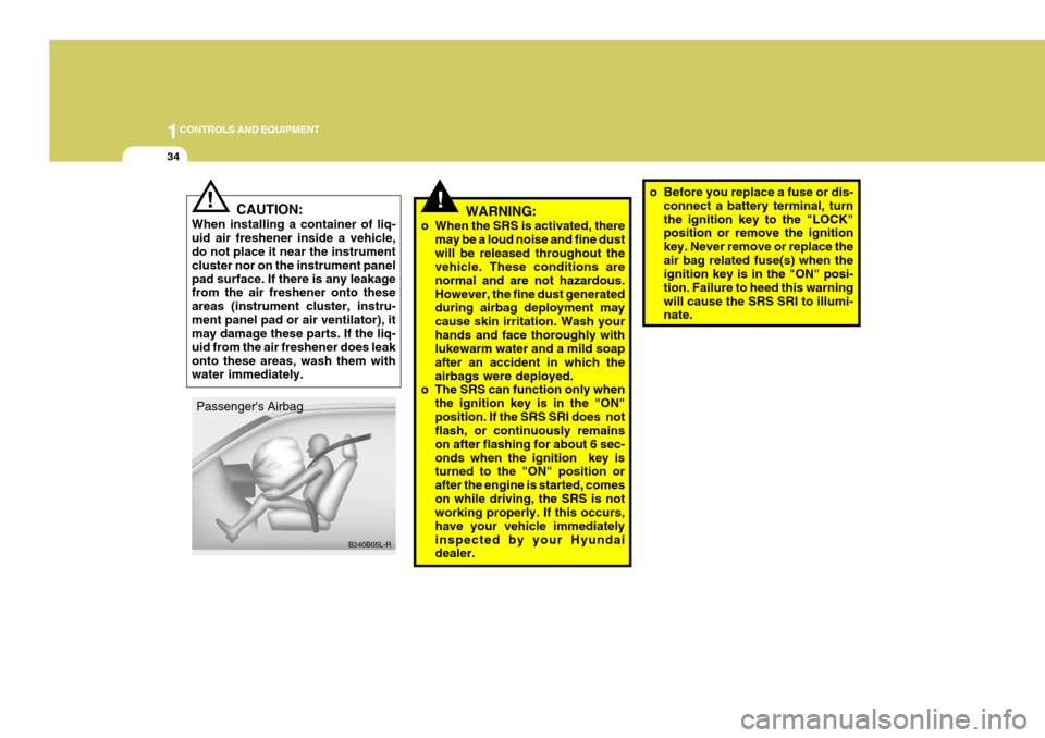
!WARNING:
o When the SRS is activated, there may be a loud noise and fine dust will be released throughout the vehicle. These conditions are normal and are not hazardous.However, the fine dust generated during airbag deployment may cause skin irritation. Wash yourhands and face thoroughly with lukewarm water and a mild soap after an accident in which theairbags were deployed.
o The SRS can function only when
the ignition key is in the "ON"position. If the SRS SRI does not flash, or continuously remains on after flashing for about 6 sec-onds when the ignition key is turned to the "ON" position or after the engine is started, comeson while driving, the SRS is not working properly. If this occurs, have your vehicle immediatelyinspected by your Hyundai dealer. o Before you replace a fuse or dis-
connect a battery terminal, turn the ignition key to the "LOCK" position or remove the ignition key. Never remove or replace theair bag related fuse(s) when the ignition key is in the "ON" posi- tion. Failure to heed this warningwill cause the SRS SRI to illumi- nate.
CAUTION:
When installing a container of liq- uid air freshener inside a vehicle, do not place it near the instrument cluster nor on the instrument panelpad surface. If there is any leakage from the air freshener onto these areas (instrument cluster, instru-ment panel pad or air ventilator), it may damage these parts. If the liq- uid from the air freshener does leakonto these areas, wash them with water immediately.!
B240B05L-R
Passenger's Airbag
Page 230 of 389

1CONTROLS AND EQUIPMENT
50MULTI FUNCTION SWITCH
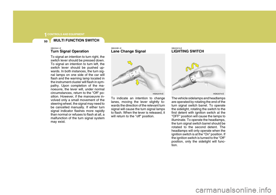
SB220A1-E Turn Signal Operation To signal an intention to turn right, the switch lever should be pressed down.To signal an intention to turn left, the switch lever should be pushed up- wards. In both instances, the turn sig-nal lamps on one side of the car will flash and the warning lamp located in the instrument cluster will flash in sym-pathy. Upon completion of the ma- noeuvre, the lever will, under normal circumstances, return to the "Off" po-sition. However, if the manoeuvre in- volved only a small movement of the steering wheel, the signal may need tobe cancelled manually. If either turn signal indicator flashes more rapidly than normal or refuses to flash at all, amalfunction of the turn signal system may exist. SB220B1-E Lane Change Signal To indicate an intention to change lanes, moving the lever slightly to- wards the direction of the relevant turnsignal will cause the turn signal lamps to flash. When the lever is released, it will return to the "off" position.
SB220C3-E LIGHTING SWITCH The vehicle sidelamps and headlamps are operated by rotating the end of the turn signal switch barrel. To operatethe sidelight, rotating the switch to the first detent with ignition switch at the "OFF" position will cause the lamps toilluminate. To operate the headlamps, the turn signal switch barrel should be rotated to the second detent. Theheadlamps will only operate when the ignition switch is at the "On" position. If the ignition switch is turned to the "Off"position, only the sidelight will func- tion.
HGK2079-E
HGK2074-E
Page 300 of 389

3 IN CASE OF EMERGENCY
2IF THE ENGINE WILL NOT START
!
SD020A1-E Seek assistance from the nearest Hyundai dealer with regard to the method of ignition and fuel system diagnosis.
WARNING:
If the engine refuses to start, noattempt should be made to push ortow start the vehicle. Vehicles with automatic transaxle or fuel injec- tion will not be able to be started in this manner since no drive is trans- mitted through the automatictransaxle whilst the engine is not running, and in the case of fuel injected derivatives, the fuel pumpwill not operate under tow start conditions. In addition, if the ve- hicle is equipped with an exhaustcatalyst, damage to the catalyst may result if the vehicle is tow started. SD020B1-E IF THE ENGINE CANNOT BE CRANKED
1. If the vehicle is fitted with manual
transaxle, ensure that the clutch pedal is depressed whilst cranking the engine. If the vehicle is fittedwith automatic transaxle, ensure that the transaxle selector is at the "P" or"N" position.
2. Check the battery terminals and connections to ensure that theseare clean and also tight.
3. If the ignition warning lamps dim when the engine is cranked and thebattery terminals have beenchecked, a discharged battery is indicated. D010B01GK
4. Do not attempt to push or tow start
the vehicle, refer to "Jump Starting" for information regarding engine starting when the battery is dis- charged.