Page 182 of 221

If the indicator remains on, or the
f uel cap was not loose or missing,
have the vehicle checked by the
dealer as soon as possible.
Your vehicle has certain ‘‘readiness
codes’’ that are part of the on-board
diagnostics f or the emissions
systems. In some states, part of the
emissions testing is to make sure
these codes are set. If they are not
set, the test cannot be completed.If your vehicle battery has been
disconnected or gone dead, these
codes are erased. If takes at least
three days of driving under various
conditions to set the codes again.
To check if they are set, turn the
ignition to ON (II), without starting
the engine. The Malf unction
Indicator Lamp will come on f or 20
seconds. If it then goes of f , the
readiness codes are set. If it blinks 5
times, the readiness codes are not
set. If possible, do not take your
vehicle f or a state emissions test
until the readiness codes are set.
Refer to State Emissions Testing for
more inf ormation (see page ).
If the indicator comes on
while driving, it means one
of the engine’s emission
control systems may have a problem.
Even though you may f eel no
dif f erence in your vehicle’s
perf ormance, continued operation
may cause serious damage.
If you have recently ref ueled your
vehicle, the indicator coming on
could be a loose or missing f uel f ill
cap. Tighten the cap until it clicks at
least three times. Tightening the cap
will not turn the indicator turn of f
immediately; it takes at least three
days of normal driving. 205
Malf unct ion Indicat or L amp
T aking Care of t he Unexpect ed
Readiness Code
183
NOTICE:If you keep driving with the
Malf unction Indicator Lamp on, you
can damage your vehicle’s emission
controls and the engine. Those repairs
may not be covered by your vehicle’s
warranties.
�����—�����—�����y�
�������������y���
�(�����������y���
�����y
Page 183 of 221

However, if the brake pedal does not
f eel normal, you should take
immediate action. A problem in one
part of the system’s dual circuit
design will still give you braking at
two wheels. You will f eel the brake
pedal go down much f arther bef ore
the vehicle begins to slow down and
you will have to press harder on the
pedal.
Slow down by shif ting to a lower
gear, and pull to the side of the road
when it is saf e. Because of the long
distance needed to stop, it is
hazardous to drive the vehicle. You
should have it towed and repaired as
soon as possible (seeon page ).
If you must drive the vehicle a short
distance in this condition, drive
slowly and caref ully.
The brake system indicator
normally comes on when
you turns the ignition
switch ON (II) and as a
reminder to check the
parking brake. It will stay lit
if you do not f ully release
the parking brake.
If the brake system indicator comes
on while drivinig, the brake f luid
level is probably low. Press lightly on
the brake pedal to see if it f eels
normal. If it does, check the brake
f luid level the next time you stop at a
service station (see page ).
If the f luid level is low, take the
vehicle to your dealer and have the
brake system inspected f or leaks or
worn brake pads. 190
151
Brake System Indicator
Emergency
Towing
T aking Care of t he Unexpect ed184
Canada U.S.
�����—�����—�����y�
�������������y���
�(�����������y���
�����y
Page 185 of 221
. Make sure the headlights and
all other accessories are off.
Remove the cover f rom t")
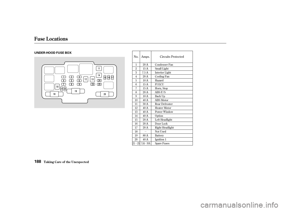
The under-hood f use box is located
onthepassenger’ssidenexttothe
battery.Turn the ignition switch to LOCK
(0). Make sure the headlights and
all other accessories are off.
Remove the cover f rom the f use
box.
Check each of the large f uses in
the under-hood f use box by
looking through the top at the wire
inside. Remove the screws with a
phillips-head screwdriver.
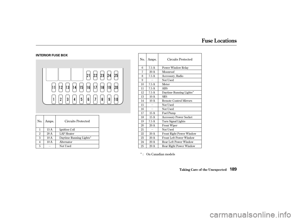
The vehicle’s f uses are located in
two fuse boxes. The interior fuse
box is located underneath the
steering column. To open it, turn the
knobsasshown.
If something electrical in your
vehicle stops working, check f or a
blown f use f irst. Determine f rom the
chart on pages and or the
diagram on the f use box lid, which
f uses control that device. Check
those fuses first, but check all the
f uses bef ore deciding that a blown
f use is the cause. Replace any blown
f uses, and check if the device works.1. 2. 3.
189
188
Fuses
T aking Care of t he Unexpect ed
Checking and Replacing Fuses
186
UNDER-HOOD
TAB
INTERIOR
FUSE
BLOWN
�����—�����—�����y�
���������
���y���
�(�����������y���
�����y
Page 187 of 221
�µ
�µ
�µ
No. Amps. Circuits Protected
1 23456789
1011121314151617181920 20 A
15 A
7.5 A 20 A
10 A
15 A
15 A
20 A
10 A
40 A
30 A
40 A
40 A
40 A
20 A
20 A
20 A
80 A
40 A Condenser Fan
Small Light
Interior Light
Cooling Fan
Hazard
FI ECU
Horn, Stop
ABS F/S
Back Up
ABS Motor
Rear Defroster
Heater Motor
Power Window
Option
Lef t Headlight
Door Lock
Right Headlight
Not Used
Battery
Ignition 1
Spare Fuses
21 257.5A 30A
Fuse Locations
T aking Care of t he Unexpect ed188
UNDER-HOOD FUSE BOX
�����—�����—�����y�
�������������y���
�(�����������y���
���
�y
Page 188 of 221
�µ�µ �µ �µ �µ
�Î
�Î
�Î
No. Amps. Circuits ProtectedNo. Amps. Circuits Protected
On Canadian models
:
1 2345 15 A
20 A
10 A
10 A
Ignition Coil
LAF Heater
Daytime Running Lights
Alternator
Not Used 6789
10111213141516171819202122232425 7.5 A
20 A
7.5 A
7.5 A
7.5 A
7.5 A 10 A
10 A
15 A
15 A
7.5 A 20 A
20 A
20 A
20 A
20 A Power Window Relay
Moonroof
Accessory, Radio
Not Used
Meter
ABS
Daytime Running Lights
SRS
Remote Control Mirrors
Not Used
Not Used
Fuel Pump
Accessory Power Socket
Turn Signal Lights
Front Wiper
Not Used
Front Right Power Window
Front Left Power Window
Rear Lef t Power Window
Rear Right Power Window
Fuse Locations
T aking Care of t he Unexpect ed189
INTERIOR FUSE BOX
�����—�����—�����y�
�������������y���
�(�����������y���
�����y
Page 190 of 221
, and keep the
speedbelow35mph(55km/h).
If your car is equipped with a f ront
spoiler, remove it bef")
With the f ront wheels on the ground,
it is best to tow the car no farther
than 50 miles (80 km), and keep the
speedbelow35mph(55km/h).
If your car is equipped with a f ront
spoiler, remove it bef ore towing so it
is not damaged.If you decide to tow your vehicle
with all f our wheels on the ground,
make sure you use a properly-
designed and attached tow bar.
Prepare the vehicle for towing as
described above, and leave the
ignition switch in Accessory (I) so
the steering wheel does not lock.
Make sure the radio and any items
plugged into the accessory power
socket are turned of f so they do not
rundownthebattery.
Emergency T owing
T aking Care of t he Unexpect ed191
NOTICE:
NOTICE: Trying to lif t or tow your
vehicle by the bumpers will cause
serious damage. The bumpers are not
designed to support the vehicle’s weight.
T he steering system can be
damaged if the steering wheel is locked.
Leave the ignition switch in Accessory
(I), and make sure the steering wheel
turns f reely bef ore you begin towing.
�����—�����—�����y�
�������������y���
�(�����������y���
�����y
Page 192 of 221

Thediagramsinthissectiongive
you the dimensions and capacities of
your Honda, and the locations of the
identif ication numbers. It also
includes inf ormation you should
know about your vehicle’s tires and
emissions control systems.................
Identif ication Numbers . 194
................................
Specif ications . 196
DOT Tire Quality Grading
......................
(U.S. Vehicles) . 198
.................................
Treadwear . 198
......................................
Traction . 198
.............................
Temperature . 199
.................................
Tire Labeling . 199
.........................
Oxygenated Fuels . 200
......
Driving in Foreign Countries . 201 .......................
Emissions Controls . 202
.....................
The Clean Air Act . 202
Crankcase Emissions Control
....................................
System . 202
Evaporative Emissions Control ....................................
System . 202
Onboard Ref ueling Vapor ................................
Recovery . 202
...
Exhaust Emissions Controls . 203
....................
PGM-FI System . 203
Ignition Timing Control
................................
System . 203
Exhaust Gas Recirculation ...................
(EGR) System . 203
Three Way Catalytic ...........................
Converter . 203
....................
Replacement Parts . 203
..
Three Way Catalytic Converter . 204
..............
State Emissions Testing . 205
T echnical Inf ormat ion
T echnical Inf ormation193
�����—�����—�����y�
�������������y���
�(�����������y���
�����y
Page 202 of 221
, and Three Way
Catalytic Converter. These three or
f")
The exhaust emissions controls
include three or f our systems: PGM-
FI, Ignition Timing Control, Exhaust
Gas Recirculation (SOHC VTEC
engine only), and Three Way
Catalytic Converter. These three or
f our systems work together to
control the engine’s combustion and
minimize the amount of HC, CO, and
NOx that comes out the tailpipe. The
exhaust emissions control systems
are separate from the crankcase and
evaporative emissions control
systems.
The PGM-FI System uses sequential
multiport f uel injection.
It has three subsystems: Air Intake,
Engine Control, and Fuel Control.
The Engine Control Module (ECM)
or the Powertrain Control Module
(PCM) uses various sensors to
determine how much air is going
into the engine. It then controls howmuch f uel to inject under all operat-
ing conditions.
This system constantly adjusts the
ignition timing, reducing the amount
of HC, CO, and NOx produced.
The Exhaust Gas Recirculation
(EGR) system takes some of the
exhaust gas and routes it back into
the intake manif old. Adding exhaust
gas to the air/f uel mixture reduces
the amount of NOx produced when
the f uel is burned.
The three way catalytic converter is
in the exhaust system. Through
chemical reactions, it converts HC,
CO, and NOx in the engine’s exhaust
to carbon dioxide (CO ), nitrogen
(N ), and water vapor.
The emissions control systems are
designed and certif ied to work to-
gether in reducing emissions to
levels that comply with the Clean Air
Act. To make sure the emissions
remain low, you should use only new
genuine Honda replacement parts or
their equivalent f or repairs. Using
lowerqualitypartsmayincreasethe
emissions f rom your vehicle.
The emissions control systems are
covered by warranties separate f rom
the rest of your vehicle. Read your
warranty manual f or more inf orma-
tion.
2
2
Emissions Cont rols
T echnical Inf ormation
Exhaust Emissions Controls Replacement Parts
PGM-FI Syst emIgnit ion T iming Cont rol Syst em
Exhaust Gas Recirculat ion (EGR)Syst em
Three Way Catalytic Converter
203
�����—�����—�����y�
�������������y���
�(�����������y���������y