2004 GMC SIERRA brake light
[x] Cancel search: brake lightPage 393 of 588
The eight-wire harness contains the following trailer
circuits:
·Yellow: Left Stop/Turn Signal
·Dark Green: Right Stop/Turn Signal
·Brown: Taillamps
·White: Ground
·Light Green: Back-up Lamps
·Light Blue: CHMSL
·Red: Battery Feed
·Dark Blue: Trailer Brake
If your trailer is equipped with electric brakes, you can
get a jumper harness (electric trailer brake control)
with a trailer battery feed fuse from your dealer.
If you need to tow a light-duty trailer with a standard
four-way round pin connector you can also get an
adapter from your dealer.
Camper/Fifth-Wheel Trailer Wiring Package
The eight-wire camper harness is located under the
front edge of the pickup box on the driver's side of the
vehicle, attached to the frame bracket. A connector
will have to be added to the wiring harness which
connects to the camper.
The eight-wire harness contains the following
camper/trailer circuits:
·Yellow: Left Stop/Turn Signal
·Dark Green: Right Stop/Turn Signal
·Brown: Taillamps
·White: Ground
·Light Green: Back-up Lamps
·Light Blue: Center High-Mounted Stoplamp
(CHMSL)
·Red: Battery Feed
·Dark Blue: Trailer Brake
4-97
Page 397 of 588
Power Winches
If you wish to use a power winch on your vehicle, only
use it when your vehicle is stationary or anchored.
Power Take-Off (PTO)
Before using a PTO, if equipped, refer to the
manufacturer's or installer's instructions.
To engage a PTO on a vehicle with a manual
transmission do the following:
1. Hold the clutch pedal down.
2. Set the parking brake.
3. Shift the transmission into NEUTRAL (N).
4. Engage the PTO. Refer to the manufacturer's or
installer's for instructions on electrically
engaged PTOs.
5. For mobile operations, shift the transmission into
the gear you want, apply the regular brakes and
release the parking brake. For stationary operations,
leave the parking brake applied.
6. Release the clutch and regular brakes as you
normally would. When the clutch is released,
the PTO will start.
7. Turn the PTO rotary switch to ON.To engage a PTO on a vehicle with an automatic
transmission do the following:
1. For stationary use shift the transmission into
PARK (P).
2. Turn the PTO rotary switch ON.
3. If the engine speed is below the PTO engage
speed limit, the PTO will start. The blinking LED
on the PTO control switch indicates PTO engage is
requested. When PTO engages the LED will
switch from blinking to a steady light.
To use PTO speed control in Preset Mode (Factory
Setting) do the following:
1. Engage the PTO
2. Select PARK (P) or NEUTRAL (N) range. Apply the
parking brake if NEUTRAL (N) is selected. Torque
Converter Clutch (TCC) is not available in
NEUTRAL (N) and is available only in PARK (P)
when engine speed is above 1,100 rpm.
3. Make sure your foot is off the brake pedal (and off
the clutch on vehicles equipped with a manual
transmission).
4. Select the desired engine speed for PTO operation.
Read the following preset mode information
regarding operation.
4-101
Page 451 of 588
Brake Wear
Your vehicle has four-wheel disc brakes.
Disc brake pads have built-in wear indicators that make
a high-pitched warning sound when the brake pads
are worn and new pads are needed. The sound
may come and go or be heard all the time your vehicle
is moving (except when you are pushing on the
brake pedal ®rmly).
{CAUTION:
The brake wear warning sound means that
soon your brakes will not work well. That
could lead to an accident. When you hear the
brake wear warning sound, have your vehicle
serviced.
Notice:Continuing to drive with worn-out brake
pads could result in costly brake repair.
Some driving conditions or climates may cause a brake
squeal when the brakes are ®rst applied or lightly
applied. This does not mean something is wrong with
your brakes.
Properly torqued wheel nuts are necessary to help
prevent brake pulsation. When tires are rotated, inspect
brake pads for wear and evenly tighten wheel nuts in
the proper sequence to GM torque speci®cations.
Brake linings should always be replaced as complete
axle sets.
Brake Pedal Travel
See your dealer if the brake pedal does not return to
normal height, or if there is a rapid increase in
pedal travel. This could be a sign of brake trouble.
Brake Adjustment
Every time you make a brake stop, your disc brakes
adjust for wear.
5-51
Page 454 of 588
3. Get the vehicles close enough so the jumper cables
can reach, but be sure the vehicles aren't touching
each other. If they are, it could cause a ground
connection you don't want. You wouldn't be able to
start your vehicle, and the bad grounding could
damage the electrical systems.
To avoid the possibility of the vehicles rolling, set
the parking brake ®rmly on both vehicles involved in
the jump start procedure. Put an automatic
transmission in PARK (P) or a manual transmission
in NEUTRAL before setting the parking brake. If
you have a four-wheel-drive vehicle, be sure
the transfer case is in a drive gear not in NEUTRAL.
Notice:If you leave your radio or other accessories
on during the jump starting procedure, they could
be damaged. The repairs would not be covered
by your warranty. Always turn off your radio and
other accessories when jump starting your vehicle.
4. Turn off the ignition on both vehicles. Unplug
unnecessary accessories plugged into the cigarette
lighter or accessory power outlets. Turn off the
radio and all lamps that aren't needed. This
will avoid sparks and help save both batteries. And
it could save your radio!5. Open the hoods and locate the positive (+) and
negative (-) terminal locations of the other vehicle.
Your vehicle has a remote positive (+) jump
starting terminal and a remote negative (-) jump
starting terminal. You should always use these
remote terminals instead of the terminals on the
battery.
The remote positive (+) terminal is located behind a
red plastic cover, if equipped, near the engine
accessory drive bracket. To uncover the remote
positive (+) terminal, open the red plastic cover, if
equipped.
The remote negative (-) terminal is located on the
engine drive bracket on all V8 and diesel engines,
and on the thermostat housing on the 8.1L engine.
On V8 engines it is marked ªGND.º
On V6 engines the remote negative (-) terminal is
located on a tab attached to the engine accessory
drive bracket where it is marked ªGND.º
See
Engine Compartment Overview on page 5-12for more information on location.
5-54
Page 481 of 588
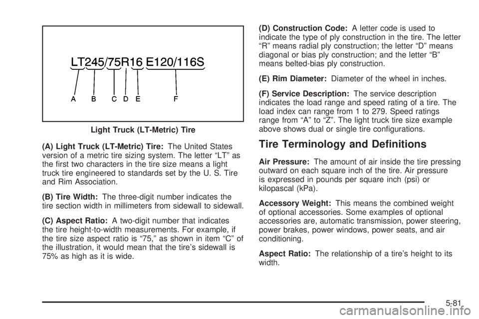
(A) Light Truck (LT-Metric) Tire:The United States
version of a metric tire sizing system. The letter ªLTº as
the ®rst two characters in the tire size means a light
truck tire engineered to standards set by the U. S. Tire
and Rim Association.
(B) Tire Width:The three-digit number indicates the
tire section width in millimeters from sidewall to sidewall.
(C) Aspect Ratio:A two-digit number that indicates
the tire height-to-width measurements. For example, if
the tire size aspect ratio is ª75,º as shown in item ªCº of
the illustration, it would mean that the tire's sidewall is
75% as high as it is wide.(D) Construction Code:A letter code is used to
indicate the type of ply construction in the tire. The letter
ªRº means radial ply construction; the letter ªDº means
diagonal or bias ply construction; and the letter ªBº
means belted-bias ply construction.
(E) Rim Diameter:Diameter of the wheel in inches.
(F) Service Description:The service description
indicates the load range and speed rating of a tire. The
load index can range from 1 to 279. Speed ratings
range from ªAº to ªZº. The light truck tire size example
above shows dual or single tire con®gurations.Tire Terminology and De®nitions
Air Pressure:The amount of air inside the tire pressing
outward on each square inch of the tire. Air pressure
is expressed in pounds per square inch (psi) or
kilopascal (kPa).
Accessory Weight:This means the combined weight
of optional accessories. Some examples of optional
accessories are, automatic transmission, power steering,
power brakes, power windows, power seats, and air
conditioning.
Aspect Ratio:The relationship of a tire's height to its
width. Light Truck (LT-Metric) Tire
5-81
Page 533 of 588

Fuses Usage
HVAC/ECAS Climate Control Controller
CIG LTR Cigarette Lighter
HI HDLP-RT High Beam Headlamp-Right
HDLP-LOW Headlamp Low Beam Relay
A/C COMP Air Conditioning Compressor
A/C COMPAir Conditioning Compressor
Relay
RR WPR Not Used
RADIO Audio System
SEO B1Mid Bussed Electrical Center,
Rear Heated Seats,
HomeLink
LO HDLP-LT Headlamp Low Beam-Left
BTSIBrake Transmission Shift
Interlock System
CRANK Starting SystemFuses Usage
LO HDLP-RT Headlamp Low Beam-Right
FOG LP Fog Lamp Relay
FOG LP Fog Lamps
HORN Horn Relay
W/S WASHWindshield Washer Pump
Relay
W/S WASH Windshield Washer Pump
INFOOnStar/Rear Seat
Entertainment
RADIO AMP Radio Ampli®er
RH HID Not Used
HORN Horn
EAP Not Used
TREC All-Wheel Drive Module
SBA Supplemental Brake Assist
5-133
Page 571 of 588
A
Accessory Power Outlets.................................3-20
Adding a Snow Plow or Similar Equipment.........4-64
Adding Washer Fluid.......................................5-46
Additional Program Information........................... 7-9
Additives, Fuel................................................. 5-6
Add-On Electrical Equipment...........................5-125
Add-On Equipment..........................................4-63
Adjusting the Speakers
(Balance/Fade)..................3-76, 3-80, 3-91, 3-105
After Off-Road Driving.....................................4-37
Air Bag
Off Light.....................................................3-37
Passenger Status Indicator...........................3-40
Readiness Light..........................................3-36
Air Bag Systems.............................................1-70
Adding Equipment to Your Air Bag-Equipped
Vehicle...................................................1-86
Air Bag Off Switch.......................................1-76
How Does an Air Bag Restrain?....................1-75
Passenger Sensing System...........................1-81
Servicing Your Air Bag-Equipped Vehicle.........1-86
What Makes an Air Bag In¯ate?....................1-74
What Will You See After an Air Bag In¯ates?......1-75
When Should an Air Bag In¯ate?...................1-73
Where Are the Air Bags?..............................1-72
Air Cleaner/Filter, Engine.................................5-23
Air Conditioning..............................................3-30
Airbag Sensing and Diagnostic Module (SDM)....7-10All Overseas Locations...................................... 7-5
AM .............................................................3-129
AM-FM Radio.................................................3-74
Antenna, Fixed Mast......................................3-131
Antenna, XMŸ Satellite Radio Antenna
System.....................................................3-131
Anti-lock Brake System..................................... 4-7
Anti-Lock Brake, System Warning Light..............3-45
Appearance Care..........................................5-116
Care of Safety Belts...................................5-119
Chemical Paint Spotting..............................5-123
Cleaning the Inside of Your Vehicle..............5-117
Cleaning the Outside of Your Vehicle............5-120
Finish Damage..........................................5-122
Sheet Metal Damage..................................5-122
Underbody Maintenance.............................5-123
Vehicle Care/Appearance Materials...............5-123
Weatherstrips............................................5-119
Approaching a Hill..........................................4-27
Ashtrays........................................................3-21
Audio Output................................................3-123
Audio System(s).............................................3-73
AM-FM Radio.............................................3-74
Audio Steering Wheel Controls....................3-128
Care of Your Cassette Tape Player...............3-129
Care of Your CD and DVD Player................3-131
Care of Your CDs and DVDs.......................3-130
Chime Level Adjustment.............................3-131
Fixed Mast Antenna...................................3-131
Radio with Cassette and CD.........................3-88
1
Page 572 of 588

Audio System(s) (cont.)
Radio with CD............................................3-77
Radio with Six-Disc CD..............................3-102
Rear Seat Audio (RSA)...............................3-126
Setting the Time for Radios with Radio Data
Systems (RDS)........................................3-74
Setting the Time for Radios without Radio
Data Systems (RDS)................................3-74
Theft-Deterrent Feature...............................3-127
Understanding Radio Reception...................3-129
XMŸ Satellite Radio Antenna System...........3-131
Automatic Dimming Mirror Operation..........2-56, 2-58
Automatic Headlamp System............................3-15
Automatic Transfer Case..................................2-39
Automatic Transmission...................................2-23
Fluid..................................................5-25, 5-28
Operation...................................................2-26
Auxiliary Battery............................................4-100
Auxiliary Roof Mounted Lamp Switch.................3-18
B
Backing Up....................................................4-92
Battery..........................................................5-52
BATTERY NOT CHARGING.............................3-66
Battery Replacement......................................... 2-6
Battery Run-Down Protection............................3-20Battery Warning Light......................................3-42
Before Leaving on a Long Trip.........................4-44
Before You Drive...........................................3-116
Before You Go Off-Roading..............................4-22
Brake
Parking......................................................2-48
System Warning Light..................................3-43
Brake Adjustment............................................5-51
Brake Fluid....................................................5-48
Brake Pedal Travel.........................................5-51
Brake Wear...................................................5-51
Brakes..........................................................5-48
Braking........................................................... 4-6
Braking in Emergencies..................................... 4-8
Break-In, New Vehicle.....................................2-21
BUCKLE PASSENGER....................................3-67
BUCKLE SEATBELT.......................................3-67
Bulb Replacement...........................................5-64
Center High-Mounted Stoplamp (CHMSL) and
Cargo Lamp............................................5-69
Front Turn Signal, Sidemarker and Daytime
Running Lamps........................................5-66
Halogen Bulbs............................................5-64
Headlamps.................................................5-64
Pickup Box Identi®cation and Fender Marker
Lamps....................................................5-70
Replacement Bulbs......................................5-74
2