Page 210 of 300
²In the Club Cab the jack and tools are stowed in a floor
compartment located under the rear seat on the pas-
senger's side of the vehicle. The seat cushion can be
lifted to a vertical position to allow access to this
compartment.
Jack Removal and Stowage
a. Quad Cab models have a Hoop±Style stowage follow
the instructions below:
²For jack removal, turn the screw counterclockwise
to remove the jack from beneath the retaining hoop.
²For jack stowage, place the jack beneath the retain-
ing hoop and turn the jack screw clockwise until the
jack is firmly secured within the retaining hoop.
Refer to the graphic below. The seat has been
removed for clarity.
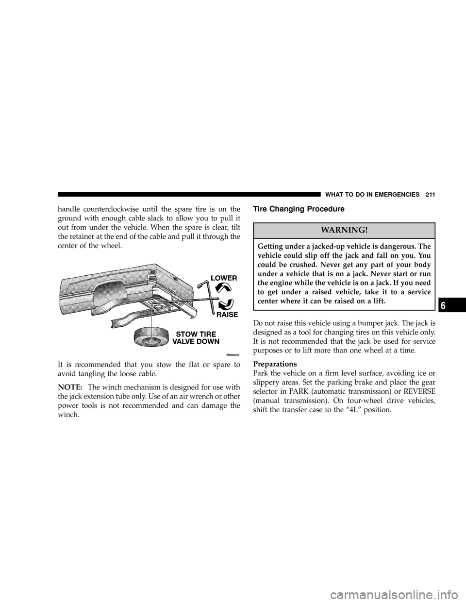
Removing The Spare Tire
Remove the spare tire before attempting to jack the truck.
Attach the wheel wrench to the jack extension tube. Insert
the tube through the access hole in the rear bumper and
into the winch mechanism tube. Rotate the wheel wrench
Quad Cab Jack Stowage
210 WHAT TO DO IN EMERGENCIES
Page 211 of 300

handle counterclockwise until the spare tire is on the
ground with enough cable slack to allow you to pull it
out from under the vehicle. When the spare is clear, tilt
the retainer at the end of the cable and pull it through the
center of the wheel.
It is recommended that you stow the flat or spare to
avoid tangling the loose cable.
NOTE:The winch mechanism is designed for use with
the jack extension tube only. Use of an air wrench or other
power tools is not recommended and can damage the
winch.
Tire Changing Procedure
WARNING!
Getting under a jacked-up vehicle is dangerous. The
vehicle could slip off the jack and fall on you. You
could be crushed. Never get any part of your body
under a vehicle that is on a jack. Never start or run
the engine while the vehicle is on a jack. If you need
to get under a raised vehicle, take it to a service
center where it can be raised on a lift.
Do not raise this vehicle using a bumper jack. The jack is
designed as a tool for changing tires on this vehicle only.
It is not recommended that the jack be used for service
purposes or to lift more than one wheel at a time.
Preparations
Park the vehicle on a firm level surface, avoiding ice or
slippery areas. Set the parking brake and place the gear
selector in PARK (automatic transmission) or REVERSE
(manual transmission). On four-wheel drive vehicles,
shift the transfer case to the ª4Lº position.
WHAT TO DO IN EMERGENCIES 211
6
Page 212 of 300

WARNING!
Do not attempt to change a tire on the side of the
vehicle close to moving traffic. Pull far enough off
the road to avoid the danger of being hit when
operating the jack or changing the wheel.
²Turn on the Hazard Warning Flasher.
²Block both the front and rear
of the wheel diagonally oppo-
site the jacking position. For
example, if the right front
wheel is being changed, block
the left rear wheel.
²Passengers should not remain in the vehicle when the
vehicle is being jacked.
Instructions
1. Remove the spare wheel, jack, and tools from storage.
2. Remove wheel center cap using the spade end of the
wheel wrench.
3. Using the wheel wrench, loosen, but do not remove,
the wheel nuts by turning them counterclockwise one
turn while the wheel is still on the ground.
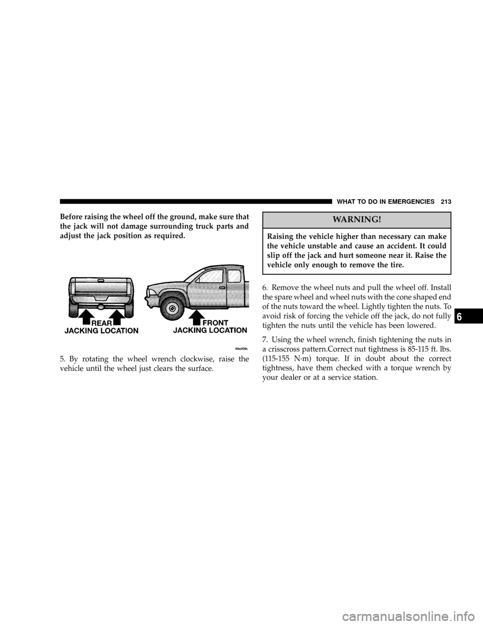
4. When changing a front wheel, place the jack under the
frame rail behind the wheel. Locate the jack as far
forward as possible on the straight part of the frame.
Make sure that the upstanding tab of the jack contacts the
vertical side of the frame. Operate the jack using the jack
drive tube and the wheel wrenchÐ the tube extension,
may be used but is not required.
When changing a rear wheel, assemble the jack drive
tube to the jack and connect the drive tube to the
extension tube. Place the jack under the axle between the
spring and the shock absorber with the drive tubes
extending to the rear. Connect the jack tube extension and
wheel wrench.
212 WHAT TO DO IN EMERGENCIES
Page 213 of 300

Before raising the wheel off the ground, make sure that
the jack will not damage surrounding truck parts and
adjust the jack position as required.
5. By rotating the wheel wrench clockwise, raise the
vehicle until the wheel just clears the surface.WARNING!
Raising the vehicle higher than necessary can make
the vehicle unstable and cause an accident. It could
slip off the jack and hurt someone near it. Raise the
vehicle only enough to remove the tire.
6. Remove the wheel nuts and pull the wheel off. Install
the spare wheel and wheel nuts with the cone shaped end
of the nuts toward the wheel. Lightly tighten the nuts. To
avoid risk of forcing the vehicle off the jack, do not fully
tighten the nuts until the vehicle has been lowered.
7. Using the wheel wrench, finish tightening the nuts in
a crisscross pattern.Correct nut tightness is 85-115 ft. lbs.
(115-155 N´m) torque. If in doubt about the correct
tightness, have them checked with a torque wrench by
your dealer or at a service station.
WHAT TO DO IN EMERGENCIES 213
6
Page 214 of 300

WARNING!
A loose tire or jack thrown forward in a collision or
hard stop could injure someone in the vehicle.
Always stow the jack parts and the extra tire and
wheel in the places provided.
8. Install wheel center cap and remove wheel blocks. Do
not install chrome or aluminum wheel center caps on the
spare wheel. This may result in cap damage.
9. Lower the jack to its fully closed position. Stow the
replaced tire, jack, and tools as previously described.
10. Adjust the tire pressure when possible.
NOTE:Do not oil wheel studs. For chrome wheels, do
not substitute with chrome plated wheel nuts.
WARNING!
Carefully follow these tire changing warnings to
help prevent personal injury or damage to your
vehicle:
²Always park on a firm, level surface as far from
the edge of the roadway as possible before raising
the vehicle.
²Block the wheel diagonally opposite the wheel to
be raised.
²Apply the parking brake firmly before jacking.
²Never start the engine with the vehicle on a jack.
²Do not let anyone sit in the vehicle when it is on
a jack.
²Do not get under the vehicle when it is on a jack.
²Only use the jack in the positions indicated.
²If working on or near a roadway, be extremely
careful of motor traffic.
214 WHAT TO DO IN EMERGENCIES
Page 220 of 300

NWindshield Wiper Blades................235
NWindshield Washers...................236
NExhaust System......................236
NCooling System.......................237
NEmission Related Components............241
NBrake System........................243
NClutch Hydraulic System................245
NManual Transmission..................245
NAutomatic Transmission................245
NTransfer Case........................248
NAxles..............................248
NSelection Of Lubricating Grease...........248
NAppearance Care And Protection From
Corrosion...........................249
mPower Distribution Center...............252
mFuse Block...........................253
mVehicle Storage........................254
mReplacement Light Bulbs................254
mBulb Replacement......................255
NHeadlights..........................255
NParking/Turn Signal Lights..............256
NRear Side Marker, Tail Lights, Turn Signals
And Backup Lights Ð Replacement........256
NLicense Lights........................257
NCenter High-Mounted Stoplight...........257
NFog Lights..........................257
mFluids And Capacities...................258
mRecommended Fluids, Lubricants And
Genuine Parts
.........................259
NEngine.............................259
NChassis............................260
220 MAINTAINING YOUR VEHICLE
Page 235 of 300

Front Suspension Ball Joints
The ball joints and seals should be inspected whenever
the vehicle is serviced for other reasons. Damaged seals
should be replaced to prevent leakage or contamination
of the grease.
Steering Linkage
Whenever the vehicle is hoisted, all steering linkage
joints should be inspected for evidence of damage. Dam-
aged seals should be replaced to prevent leakage or
contamination of the grease.
Drive Shaft Constant Velocity Joints Ð 4X4
Models
All four-wheel drive models are equipped with four
constant velocity joints. Periodic lubrication of these
joints is not required. However, the joint boot should be
inspected for external leakage or damage periodically. If
external leakage or damage is evident, the joint boot and
grease should be replaced immediately. Continued op-
eration could result in failure of the joint due to water
and dirt contamination of the grease. This would require
complete replacement of the joint assembly. Refer to the
Service Manual for the detailed replacement procedure.
Body Lubrication
Locks and all body pivot points, including such items as
seat tracks, doors,liftgate and hood hinges, should be
lubricated periodically to assure quiet, easy operation
and to protect against rust and wear. Prior to the appli-
cation of any lubricant, the parts concerned should be
wiped clean to remove dust and grit; after lubricating
excess oil and grease should be removed. Particular
attention should also be given to hood latching compo-
nents to insure proper function. When performing other
underhood services, the hood latch, release mechanism
and safety catch should be cleaned and lubricated.
The external lock cylinders should be lubricated twice a
year, preferably in the fall and spring. Apply a small
amount of a high quality lubricant such as MopartLock
Cylinder Lubricant directly into the lock cylinder.
Windshield Wiper Blades
The rubber edges of the wiper blades and the windshield
should be cleaned periodically with a sponge or soft cloth
and a mild nonabrasive cleaner. This will remove accu-
mulations of salt or road film.
MAINTAINING YOUR VEHICLE 235
7
Page 253 of 300
This power center houses plug-in cartridge and relays. A
label inside the latching cover of the center identifies each
component for ease of replacement, if necessary. Car-
tridge fuses and relays can be obtained from your Dodge
dealer.
FUSE BLOCK
The fuse block contains blade-type mini-fuses, relays,
and circuit breakers for high-current circuits. It is located
just inboard of the left end of the instrument panel,
behind the panel surface. It is accessible through a
snap-in cover. Refer to the label on the backside of the
fuse block cover for the proper fuse amperage and
position.
CAUTION!
When replacing a blown fuse, it is important to use
only a fuse having the correct amperage rating. The
use of a fuse with a rating other than indicated may
result in a dangerous electrical system overload. If a
properly rated fuse continues to blow, it suggests a
problem in the circuit that must be corrected.
MAINTAINING YOUR VEHICLE 253
7