2004 DAEWOO NUBIRA cylinder head
[x] Cancel search: cylinder headPage 1941 of 2643

6C – 24IPOWER STEERING GEAR
DAEWOO V–121 BL4
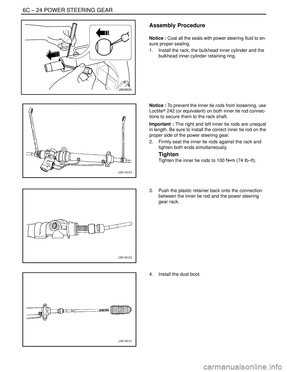
Assembly Procedure
Notice : Coat all the seals with power steering fluid to en-
sure proper sealing.
1. Install the rack, the bulkhead inner cylinder and the
bulkhead inner cylinder retaining ring.
Notice : To prevent the inner tie rods from loosening, use
Loctite® 242 (or equivalent) on both inner tie rod connec-
tions to secure them to the rack shaft.
Important : The right and left inner tie rods are unequal
in length. Be sure to install the correct inner tie rod on the
proper side of the power steering gear.
2. Firmly seat the inner tie rods against the rack and
tighten both ends simultaneously.
Tighten
Tighten the inner tie rods to 100 NSm (74 lb–ft).
3. Push the plastic retainer back onto the connection
between the inner tie rod and the power steering
gear rack.
4. Install the dust boot.
Page 1955 of 2643

SECTION : 6E
STEERING WHEEL AND COLUMN
CAUTION : Disconnect the negative battery cable before removing or installing any electrical unit or when a tool
or equipment could easily come in contact with exposed electrical terminals. Disconnecting this cable will help
prevent personal injury and damage to the vehicle. The ignition must also be in LOCK unless otherwise noted.
TABLE OF CONTENTS
SPECIFICATIONS6E–1 . . . . . . . . . . . . . . . . . . . . . . . . . .
Fastener Tightening Specifications 6E–1. . . . . . . . . . .
SPECIAL TOOLS6E–2 . . . . . . . . . . . . . . . . . . . . . . . . . . .
Special Tools Table 6E–2. . . . . . . . . . . . . . . . . . . . . . . .
DIAGNOSIS6E–2 . . . . . . . . . . . . . . . . . . . . . . . . . . . . . . . .
Steering Column Diagnosis 6E–2. . . . . . . . . . . . . . . . .
MAINTENANCE AND REPAIR6E–8 . . . . . . . . . . . . . . .
ON–VEHICLE SERVICE 6E–8. . . . . . . . . . . . . . . . . . . . .
Headlamp/Turn Signal Switch and Lever 6E–8. . . . . .
Wiper Switch and Lever 6E–9. . . . . . . . . . . . . . . . . . . . Steering Wheel Rotation Sensor 6E–10. . . . . . . . . . . .
Steering Wheel Without SIR 6E–11. . . . . . . . . . . . . . . .
Steering Wheel With SIR 6E–13. . . . . . . . . . . . . . . . . .
Ignition Lock Cylinder and Switch 6E–13. . . . . . . . . . .
Steering Column 6E–15. . . . . . . . . . . . . . . . . . . . . . . . . .
UNIT REPAIR 6E–19. . . . . . . . . . . . . . . . . . . . . . . . . . . . .
Tilt Steering Column 6E–19. . . . . . . . . . . . . . . . . . . . . .
GENERAL DESCRIPTION AND SYSTEM
OPERATION6E–20 . . . . . . . . . . . . . . . . . . . . . . . . . . . . .
Steering Wheel and Column 6E–20. . . . . . . . . . . . . . . .
Ignition Key Reminder 6E–20. . . . . . . . . . . . . . . . . . . . .
SPECIFICATIONS
FASTENER TIGHTENING SPECIFICATIONS
ApplicationNSmLb–FtLb–In
Ignition Switch Housing Shear Bolts11–97
Ignition Switch Retaining Screw2.5–22
Steering Column Jacket Assembly Front Bracket Bolts2216–
Steering Column Jacket Assembly Rear Bracket Nuts2216–
Steering Shaft Universal Joint Pinch Bolt2518–
Steering Wheel Horn Cap Screws4.5–40
Steering Wheel Nut3828–
Steering Wheel Rotation Sensor Retaining Screw2–18
Support Housing Screws1612–
Turn Signal Switch Housing Screws3–27
Upper and Lower Steering Column Cover Panel Screws2.5–22
Page 1974 of 2643

6E – 20ISTEERING WHEEL AND COLUMN
DAEWOO V–121 BL4
GENERAL DESCRIPTION
AND SYSTEM OPERATION
STEERING WHEEL AND COLUMN
CAUTION : To ensure the energy–absorbing action of
the steering column, it is important to use only the
specified screws, bolts, and nuts, tightened to the
specified torque.
In addition to the steering function, the steering column
provides safety and security.
The energy–absorbing column is designed to compress in
a front–end collision to lessen the chance of driver injury.
The ignition switch and the lock are mounted on the col-
umn, allowing the ignition and steering operations to be
locked to inhibit theft of the car.
The column levers trigger the turn signals, the headlight
beams, and the windshield washer and wipers.The tilt steering column uses telescopic function to allow
the steering wheel to tilt up and down in and out. This en-
ables the driver to adjust the steering wheel to a comfort-
able position.
Notice : Apply a thin coat of lithium grease to all friction
points when reassembling.
The column may be disassembled and reassembled easi-
ly.IGNITION KEY REMINDER
The ignition key reminder alerts the driver that the key is
still in the ignition when the driver attempts to exit the ve-
hicle.
An internal switch in the ignition lock cylinder supplies bat-
tery voltage to the reminder chime module when all of the
following conditions are true:
S The key is in the ignition switch.
S The ignition is OFF.
S The driver’s door is open.
For information on removal and installation of the reminder
chime module, refer to Section 9E, Instrumentation/Driver
Information.
Page 2003 of 2643

SECTION : 7B
MANUAL CONTROL HEATING, VENTILATION
AND AIR CONDITIONING SYSTEM
CAUTION : Disconnect the negative battery cable before removing or installing any electrical unit or when a tool
or equipment could easily come in contact with exposed electrical terminals. Disconnecting this cable will help
prevent personal injury and damage to the vehicle. The ignition must also be in LOCK unless otherwise noted.
TABLE OF CONTENTS
SPECIFICATIONS7B–2 . . . . . . . . . . . . . . . . . . . . . . . . . .
General Specifications 7B–2. . . . . . . . . . . . . . . . . . . . .
Fastener Tightening Specifications 7B–2. . . . . . . . . . .
SPECIAL TOOLS7B–3 . . . . . . . . . . . . . . . . . . . . . . . . . . .
Special Tools Table 7B–3. . . . . . . . . . . . . . . . . . . . . . . .
SCHEMATIC AND ROUTING DIAGRAMS7B–6 . . . . .
A/C System – Typical 7B–6. . . . . . . . . . . . . . . . . . . . . .
Manual Control A/C Diagram 7B–7. . . . . . . . . . . . . . . .
DIAGNOSIS7B–8 . . . . . . . . . . . . . . . . . . . . . . . . . . . . . . . .
GENERAL DIAGNOSIS 7B–8. . . . . . . . . . . . . . . . . . . . . .
Testing the Refrigerant System 7B–8. . . . . . . . . . . . . .
Insufficient Cooling ”Quick Check” Procedure 7B–8. .
A/C Performance Test 7B–9. . . . . . . . . . . . . . . . . . . . . .
Pressure–Temperature Relationship of
R–134A 7B–10. . . . . . . . . . . . . . . . . . . . . . . . . . . . . . .
Leak Testing Refrigerant System 7B–11. . . . . . . . . . . .
V5 SYSTEM AIR CONDITIONING DIAGNOSIS 7B–12
Insufficient Cooling Diagnosis 7B–12. . . . . . . . . . . . . .
SYMPTOM DIAGNOSIS 7B–16. . . . . . . . . . . . . . . . . . . .
Pressure Test Chart (R–134A System) 7B–16. . . . . .
Low and High Side Pressure Relationship
Chart 7B–18. . . . . . . . . . . . . . . . . . . . . . . . . . . . . . . . . .
MAINTENANCE AND REPAIR7B–19 . . . . . . . . . . . . . .
ON–VEHICLE SERVICE 7B–19. . . . . . . . . . . . . . . . . . . .
GENERAL A/C SYSTEM SERVICE
PROCEDURES 7B–19. . . . . . . . . . . . . . . . . . . . . . . . . .
O–Ring Replacement 7B–19. . . . . . . . . . . . . . . . . . . . .
Handling Refrigerant 7B–19. . . . . . . . . . . . . . . . . . . . . .
Handling of Refrigerant Lines and Fittings 7B–19. . . .
Maintaining Chemical Stability in the Refrigeration
System 7B–20. . . . . . . . . . . . . . . . . . . . . . . . . . . . . . . .
Discharging, Adding Oil, Evacuating, and Charging
Procedures for A/C System 7B–20. . . . . . . . . . . . . .
SERVICEABLE COMPONENTS 7B–23. . . . . . . . . . . . . Components Used In Non–A/C Systems 7B–23. . . . .
A/C Pressure Transducer 7B–24. . . . . . . . . . . . . . . . . .
A/C Compressor Relay 7B–24. . . . . . . . . . . . . . . . . . . .
Air Filter 7B–25. . . . . . . . . . . . . . . . . . . . . . . . . . . . . . . . .
A/C Expansion Valve 7B–25. . . . . . . . . . . . . . . . . . . . . .
A/C High–Pressure Pipe Line 7B–26. . . . . . . . . . . . . . .
Evaporator Core 7B–29. . . . . . . . . . . . . . . . . . . . . . . . . .
A/C Suction Hose Assembly 7B–30. . . . . . . . . . . . . . .
A/C Discharge Hose Compressor to
Condenser 7B–31. . . . . . . . . . . . . . . . . . . . . . . . . . . . .
Receiver–Dryer 7B–32. . . . . . . . . . . . . . . . . . . . . . . . . . .
Compressor 7B–33. . . . . . . . . . . . . . . . . . . . . . . . . . . . . .
Condenser 7B–35. . . . . . . . . . . . . . . . . . . . . . . . . . . . . . .
UNIT REPAIR 7B–37. . . . . . . . . . . . . . . . . . . . . . . . . . . . .
COMPONENT LOCATOR 7B–37. . . . . . . . . . . . . . . . . . .
V5 Compressor 7B–37. . . . . . . . . . . . . . . . . . . . . . . . . . .
V5 AIR CONDITIONING COMPRESSOR
OVERHAUL 7B–38. . . . . . . . . . . . . . . . . . . . . . . . . . . . .
Clutch Plate and Hub Assembly 7B–38. . . . . . . . . . . .
Clutch Rotor and Bearing 7B–40. . . . . . . . . . . . . . . . . .
Clutch Coil 7B–42. . . . . . . . . . . . . . . . . . . . . . . . . . . . . . .
Shaft Seal Replacement 7B–44. . . . . . . . . . . . . . . . . . .
Control Valve Assembly 7B–46. . . . . . . . . . . . . . . . . . .
Rear Head, Gasket, Valve Plate, Reed Plate,
and O–ring 7B–47. . . . . . . . . . . . . . . . . . . . . . . . . . . . .
Cylinder to Front Head O–ring 7B–48. . . . . . . . . . . . . .
Leak Testing (External) 7B–50. . . . . . . . . . . . . . . . . . . .
GENERAL DESCRIPTION AND SYSTEM
OPERATION7B–51 . . . . . . . . . . . . . . . . . . . . . . . . . . . . .
GENERAL INFORMATION 7B–51. . . . . . . . . . . . . . . . . .
The V5 A/C System 7B–51. . . . . . . . . . . . . . . . . . . . . . .
System Components – Functional 7B–51. . . . . . . . . .
System Components – Control 7B–52. . . . . . . . . . . . .
V5 Compressor – General Description 7B–52. . . . . . .
V5 Compressor – Description of Operation 7B–52. . .
Page 2039 of 2643

MANUAL CONTROL HEATING, VENTILATION AND AIR CONDITIONING SYSTEM 7B – 37
DAEWOO V–121 BL4
UNIT REPAIR
COMPONENT LOCATOR
V5 COMPRESSOR
1. Rear Head Compressor
2. Control Valve O–Ring
3. Rear Head Gasket
4. Valve Plate
5. Suction Reed
6. Clutch Coil
7. Retaining Ring
8. Drive Plate Clutch
9. Pulley Bearing
10. Clutch Hub Key
11. Shaft Nut
12. Seal Retaining Ring
13. Shaft Lip Seal
14. Shaft Seal O–Ring
15. Compressor Housing16. Compressor Control Valve
17. Pulley Bearing–to–Head Retaining Ring
18. Rotor Pulley
19. Through–Bolt
20. Through–Gasket
21. Compressor Housing–to–Cylinder O–Ring
22. Shaft and Guide Pin Assembly Cylinder
23. Rear Head O–Ring
24. Thrust Washer
25. Race
26. Bearing
27. Oil Drain Plug
28. Clutch and Hub Keyway
29. Compressor Shaft
Page 2049 of 2643

MANUAL CONTROL HEATING, VENTILATION AND AIR CONDITIONING SYSTEM 7B – 47
DAEWOO V–121 BL4
REAR HEAD, GASKET, VALVE
PLATE, REED PLATE, AND O–RING
Tools Required
J–34993 Cylinder Alignment Rods
Removal Procedure
1. Recover the refrigerant. Refer to ”Discharging, Add-
ing Oil, Evacuating, and Charging Procedures for
A/C System” in this section.
2. Discharge the A/C system. Refer to ”Discharging,
Adding Oil, Evacuating, and Charging Procedures
for A/C System” in this section.
3. Remove the compressor. Refer to ”Compressor” in
this section.
4. Drain the oil from compressor into a suitable con-
tainer. Measure and record the amount of oil
drained from the compressor. Discard the used oil.
5. Remove the clutch plate and hub assembly. Refer
to ”Clutch Plate and Hub Assembly” in this section.
6. Remove the clutch rotor and bearing. Refer to
”Clutch Rotor and Bearing” in this section.
7. Remove the clutch coil. Refer to ”Clutch Coil” in
this section.
8. Remove the compressor through–bolts. Remove
and discard the gaskets.
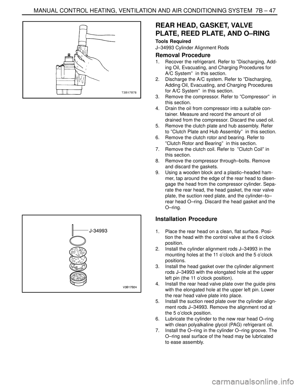
9. Using a wooden block and a plastic–headed ham-
mer, tap around the edge of the rear head to disen-
gage the head from the compressor cylinder. Sepa-
rate the rear head, the head gasket, the rear valve
plate, the suction reed plate, and the cylinder–to–
rear head O–ring. Discard the head gasket and the
O–ring.
Installation Procedure
1. Place the rear head on a clean, flat surface. Posi-
tion the head with the control valve at the 6 o’clock
position.
2. Install the cylinder alignment rods J–34993 in the
mounting holes at the 11 o’clock and the 5 o’clock
positions.
3. Install the head gasket over the cylinder alignment
rods J–34993 with the elongated hole at the upper
left pin (the 11 o’clock position).
4. Install the rear head valve plate over the guide pins
with the elongated hole at the upper left pin. Lower
the rear head valve plate into place.
5. Install the suction reed plate over the cylinder align-
ment rods J–34993. Remove the alignment rod at
the 5 o’clock position.
6. Lubricate the cylinder to the new rear head O–ring
with clean polyalkaline glycol (PAG) refrigerant oil.
7. Install the O–ring in the cylinder O–ring groove. The
O–ring seal surface of the head may be lubricated
to ease assembly.
Page 2050 of 2643

7B – 48IMANUAL CONTROL HEATING, VENTILATION AND AIR CONDITIONING SYSTEM
DAEWOO V–121 BL4
8. With the O–ring in place on the rear of the cylinder
assembly, locate the relief boss for the compressor
guide pin at the 6 o’clock position, directly above
the hole in the side of the rear head. Carefully lower
the cylinder and the front head assembly over the
guide pin to the rear head.
9. Press the cylinder and the compressor housing as-
sembly down onto the rear head using both hands.
10. Add the new through–bolt gasket to the through–
bolts and install it into the compressor assembly.
Four of the through–bolts must thread into the rear
head before removing the alignment rod.
Tighten
Alternately tighten the through–bolts in progressive
torque sequence to 10 NSm (89 lb–in).
11. Add new PAG refrigerant oil as determined in Step
1 of Removal Procedure.
12. Place the shaft nut on the shaft and rotate the com-
pressor shaft several times.
13. Perform a leak test on the compressor. Refer to
”Leak Testing (External)” in this section.
14. Install the clutch coil. Refer to ”Clutch Coil” in this
section.
15. Install the clutch rotor and bearing. Refer to ”Clutch
Rotor and Bearing” in this section.
16. Install the clutch plate and hub assembly. Refer to
”Clutch Plate and Hub Assembly” in this section.
17. Install the compressor. Refer to ”Compressor” in
this section.
18. Evacuate and recharge the A/C system. Refer to
”Discharging, Adding Oil, Evacuating, and Charging
Procedures for A/C System” in this section.
CYLINDER–TO–FRONT HEAD
O–RING
Tools Required
J–34993 Cylinder Alignment Rods
J–35372 Support Block
Removal Procedure
1. Recover the refrigerant. Refer to ”Discharging, Add-
ing Oil, Evacuating, and Charging Procedures for
A/C System” in this section.
2. Remove the compressor. Refer to ”Compressor” in
this section.
3. Drain the oil from compressor into a suitable con-
tainer. Measure and record the amount of oil
drained from the compressor. Discard all used oil.
4. Remove the clutch plate and hub assembly. Refer
to ”Clutch Plate and Hub Assembly” in this section.
5. Remove the clutch rotor and bearing. Refer to
”Clutch Rotor and Bearing” in this section.
6. Remove the clutch coil. Refer to ”Clutch Coil” in
this section.
Page 2051 of 2643

MANUAL CONTROL HEATING, VENTILATION AND AIR CONDITIONING SYSTEM 7B – 49
DAEWOO V–121 BL4
7. Remove and discard the shaft seal parts. Refer to
”Shaft Seal Replacement” in this section.
8. Remove the compressor through–bolts. Remove
and discard the gaskets.
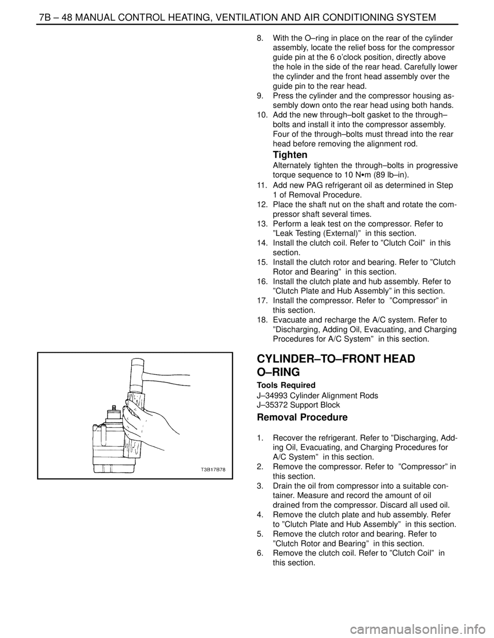
9. Using a wooden block and a plastic–headed ham-
mer, tap the compressor housing at the mounting
locations to disengage the housing from the com-
pressor cylinder.
Important : Note the assembly sequence of the thrust
washer and bearing for ease of assembly.
10. Remove the thrust washer and the bearing.
11. Remove and discard the compressor housing–to–
cylinder O–ring.
Installation Procedure
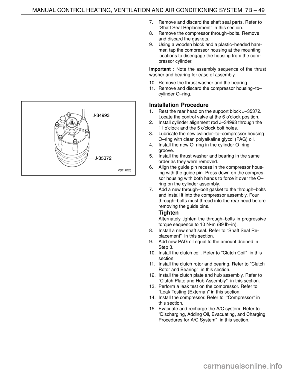
1. Rest the rear head on the support block J–35372.
Locate the control valve at the 6 o’clock position.
2. Install cylinder alignment rod J–34993 through the
11 o’clock and the 5 o’clock bolt holes.
3. Lubricate the new cylinder–to–compressor housing
O–ring with clean polyalkaline glycol (PAG) oil.
4. Install the new O–ring in the cylinder O–ring
groove.
5. Install the thrust washer and bearing in the same
order as they were removed.
6. Align the guide pin recess in the compressor hous-
ing with the guide pin. Press down on the compres-
sor housing with both hands to force it over the O–
ring on the cylinder assembly.
7. Add a new through–bolt gasket to the through–bolts
and install it into the compressor assembly. Four
through–bolts must thread into the rear head before
removing the guide pins.
Tighten
Alternately tighten the through–bolts in progressive
torque sequence to 10 NSm (89 lb–in).
8. Install a new shaft seal. Refer to ”Shaft Seal Re-
placement” in this section.
9. Add new PAG oil equal to the amount drained in
Step 3.
10. Install the clutch coil. Refer to ”Clutch Coil” in this
section.
11. Install the clutch rotor and bearing. Refer to ”Clutch
Rotor and Bearing” in this section.
12. Install the clutch plate and hub assembly. Refer to
”Clutch Plate and Hub Assembly” in this section.
13. Perform a leak test on the compressor. Refer to
”Leak Testing (External)” in this section.
14. Install the compressor. Refer to ”Compressor” in
this section.
15. Evacuate and recharge the A/C system. Refer to
”Discharging, Adding Oil, Evacuating, and Charging
Procedures for A/C System” in this section.