Page 136 of 2643
1C2 – 16I1.8L DOHC ENGINE MECHANICAL
DAEWOO V–121 BL4
40. Remove the timing belt idler pulley bolt and nut.
41. Remove the timing belt idler pulleys.
42. Remove the engine mount bolts.
43. Remove the engine mount.
44. Remove the rear timing belt cover bolts.
45. Remove the rear timing belt cover.
46. Remove the exhaust flex pipe retaining nuts at the
exhaust manifold studs.
47. Disconnect all of the necessary vacuum hoses.
48. Disconnect the fuel feed line at the fuel rail.
49. Remove the generator adjusting bracket retaining
bolt and the bracket.
50. Disconnect the coolant hose at the rear cylinder
head and ignition coil exhaust gas recirculation
(EGR) bracket.
51. Disconnect the surge tank coolant hose at the
throttle body.
52. Remove the fuel rail assembly. Refer to Section 1F,
Engine Controls.
Page 137 of 2643
1.8L DOHC ENGINE MECHANICAL 1C2 – 17
DAEWOO V–121 BL4
53. Remove the generator–to–intake manifold support
bracket bolts at the cylinder head and the intake
manifold.
54. Remove the generator support bracket.
55. Remove the intake manifold–to–generator strap
bracket bolt and loosen the bolt on the generator.
56. Move the strap clear of the intake manifold.
57. Remove the charcoal canister purge (CCP) and
EGR solenoid bracket bolt and move the bracket
clear.
58. Disconnect the throttle cable at the throttle body
and the intake manifold.
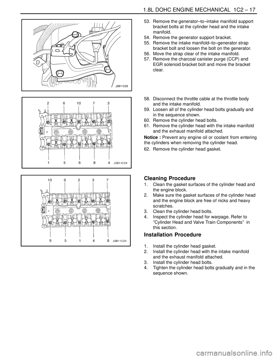
59. Loosen all of the cylinder head bolts gradually and
in the sequence shown.
60. Remove the cylinder head bolts.
61. Remove the cylinder head with the intake manifold
and the exhaust manifold attached.
Notice : Prevent any engine oil or coolant from entering
the cylinders when removing the cylinder head.
62. Remove the cylinder head gasket.
Cleaning Procedure
1. Clean the gasket surfaces of the cylinder head and
the engine block.
2. Make sure the gasket surfaces of the cylinder head
and the engine block are free of nicks and heavy
scratches.
3. Clean the cylinder head bolts.
4. Inspect the cylinder head for warpage. Refer to
”Cylinder Head and Valve Train Components” in
this section.
Installation Procedure
1. Install the cylinder head gasket.
2. Install the cylinder head with the intake manifold
and the exhaust manifold attached.
3. Install the cylinder head bolts.
4. Tighten the cylinder head bolts gradually and in the
sequence shown.
Page 138 of 2643
1C2 – 18I1.8L DOHC ENGINE MECHANICAL
DAEWOO V–121 BL4
Tighten
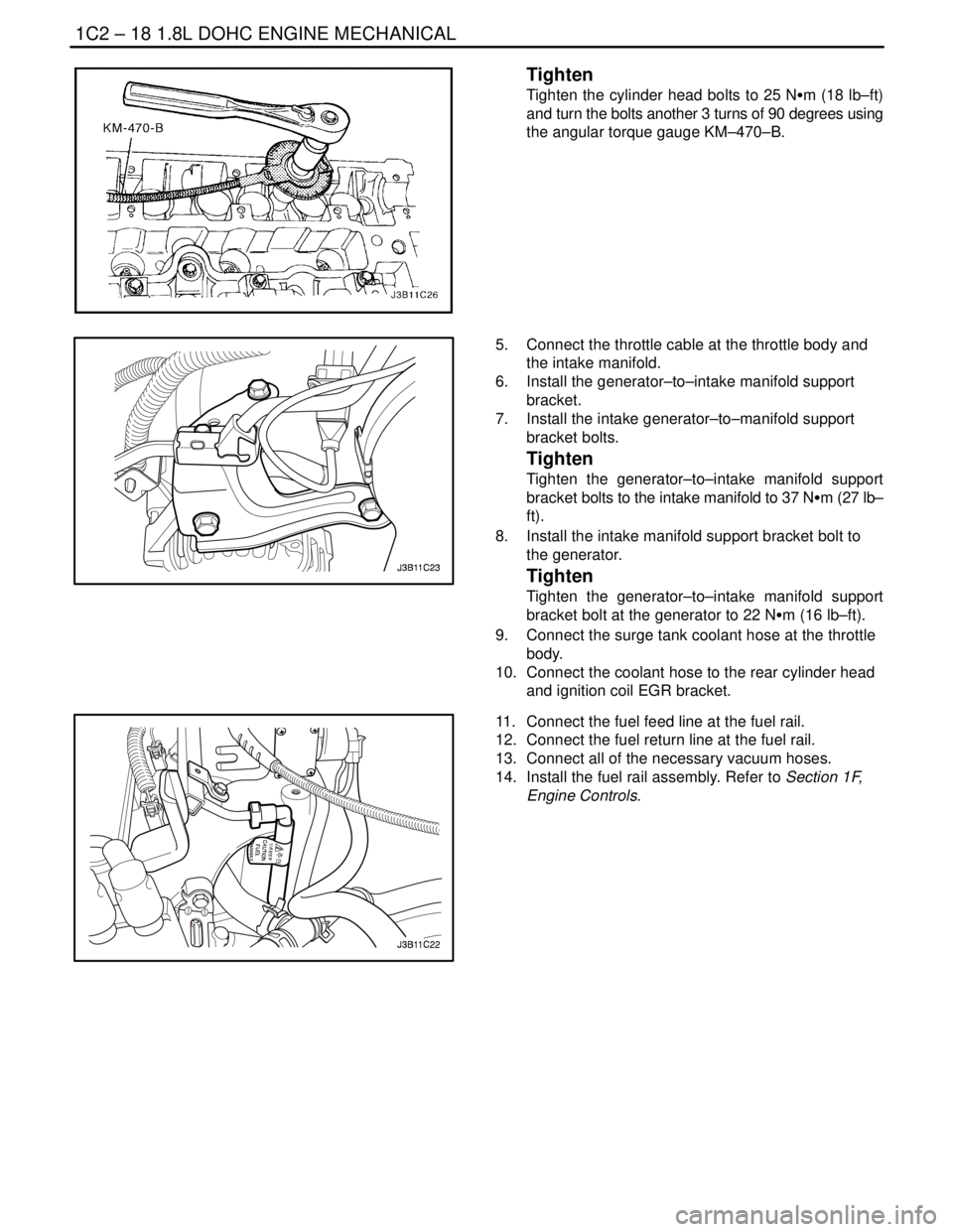
Tighten the cylinder head bolts to 25 NSm (18 lb–ft)
and turn the bolts another 3 turns of 90 degrees using
the angular torque gauge KM–470–B.
5. Connect the throttle cable at the throttle body and
the intake manifold.
6. Install the generator–to–intake manifold support
bracket.
7. Install the intake generator–to–manifold support
bracket bolts.
Tighten
Tighten the generator–to–intake manifold support
bracket bolts to the intake manifold to 37 NSm (27 lb–
ft).
8. Install the intake manifold support bracket bolt to
the generator.
Tighten
Tighten the generator–to–intake manifold support
bracket bolt at the generator to 22 NSm (16 lb–ft).
9. Connect the surge tank coolant hose at the throttle
body.
10. Connect the coolant hose to the rear cylinder head
and ignition coil EGR bracket.
11. Connect the fuel feed line at the fuel rail.
12. Connect the fuel return line at the fuel rail.
13. Connect all of the necessary vacuum hoses.
14. Install the fuel rail assembly. Refer to Section 1F,
Engine Controls.
Page 140 of 2643
1C2 – 20I1.8L DOHC ENGINE MECHANICAL
DAEWOO V–121 BL4
Tighten
Tighten the exhaust camshaft gear bolt to 50 NSm (37
lb–ft) turn the bolt another 60 degrees and 15 degrees
using the angular torque gauge.
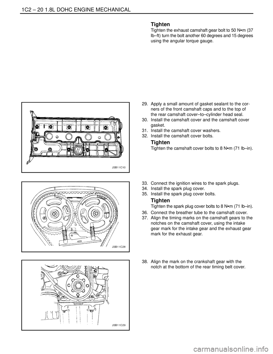
29. Apply a small amount of gasket sealant to the cor-
ners of the front camshaft caps and to the top of
the rear camshaft cover–to–cylinder head seal.
30. Install the camshaft cover and the camshaft cover
gasket.
31. Install the camshaft cover washers.
32. Install the camshaft cover bolts.
Tighten
Tighten the camshaft cover bolts to 8 NSm (71 lb–in).
33. Connect the ignition wires to the spark plugs.
34. Install the spark plug cover.
35. Install the spark plug cover bolts.
Tighten
Tighten the spark plug cover bolts to 8 NSm (71 lb–in).
36. Connect the breather tube to the camshaft cover.
37. Align the timing marks on the camshaft gears to the
notches on the camshaft cover, using the intake
gear mark for the intake gear and the exhaust gear
mark for the exhaust gear.
38. Align the mark on the crankshaft gear with the
notch at the bottom of the rear timing belt cover.
Page 143 of 2643
1.8L DOHC ENGINE MECHANICAL 1C2 – 23
DAEWOO V–121 BL4
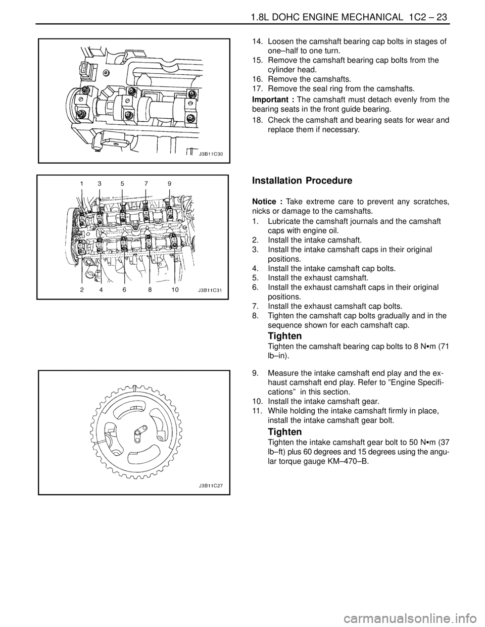
14. Loosen the camshaft bearing cap bolts in stages of
one–half to one turn.
15. Remove the camshaft bearing cap bolts from the
cylinder head.
16. Remove the camshafts.
17. Remove the seal ring from the camshafts.
Important : The camshaft must detach evenly from the
bearing seats in the front guide bearing.
18. Check the camshaft and bearing seats for wear and
replace them if necessary.
Installation Procedure
Notice : Take extreme care to prevent any scratches,
nicks or damage to the camshafts.
1. Lubricate the camshaft journals and the camshaft
caps with engine oil.
2. Install the intake camshaft.
3. Install the intake camshaft caps in their original
positions.
4. Install the intake camshaft cap bolts.
5. Install the exhaust camshaft.
6. Install the exhaust camshaft caps in their original
positions.
7. Install the exhaust camshaft cap bolts.
8. Tighten the camshaft cap bolts gradually and in the
sequence shown for each camshaft cap.
Tighten
Tighten the camshaft bearing cap bolts to 8 NSm (71
lb–in).
9. Measure the intake camshaft end play and the ex-
haust camshaft end play. Refer to ”Engine Specifi-
cations” in this section.
10. Install the intake camshaft gear.
11. While holding the intake camshaft firmly in place,
install the intake camshaft gear bolt.
Tighten
Tighten the intake camshaft gear bolt to 50 NSm (37
lb–ft) plus 60 degrees and 15 degrees using the angu-
lar torque gauge KM–470–B.
Page 159 of 2643

1.8L DOHC ENGINE MECHANICAL 1C2 – 39
DAEWOO V–121 BL4
8. Disconnect the idle air control (IAC) valve connec-
tor.
9. Disconnect the throttle position sensor (TPS) con-
nector.
10. Disconnect the manifold absolute pressure (MAP)
sensor connector.
11. Disconnect the coolant hoses at the throttle body.
12. Disconnect all of the necessary vacuum hoses, in-
cluding the vacuum hose at the fuel pressure regu-
lator and the brake booster vacuum hose at the
intake manifold.
13. Disconnect the throttle cable from the throttle body
and the intake manifold.
14. Remove the throttle cable bracket bolts from the
intake manifold.
15. Remove the throttle cable bracket.
16. Remove the generator–to–intake manifold strap
bracket bolts and strap.
17. Remove the fuel rail as an assembly. Refer to Sec-
tion 1F, Engine Controls.
18. Remove the generator–to–intake manifold support
bracket bolts.
19. Remove the generator–to–intake manifold support
bracket.
20. Remove the intake manifold support bracket bolt at
the engine block and the intake manifold.
21. Remove the intake manifold support bracket.
22. Remove the intake manifold retaining bolt and nuts
in the sequence shown.
23. Remove the intake manifold.
24. Remove the intake manifold gasket.
25. Clean the sealing surfaces of the intake manifold
and the cylinder head.
Page 162 of 2643
1C2 – 42I1.8L DOHC ENGINE MECHANICAL
DAEWOO V–121 BL4
6. Remove the exhaust manifold retaining nuts in the
sequence shown.
7. Remove the exhaust manifold.
8. Remove the exhaust manifold gasket.
9. Clean the sealing surfaces of the exhaust manifold
and the cylinder head.
Installation Procedure
1. Install the exhaust manifold gasket.
2. Install the exhaust manifold.
3. Install the exhaust manifold retaining nuts and tight-
en in the sequence shown.
Tighten
Tighten the exhaust manifold retaining nuts 22 NSm
(16 lb–ft).
4. Install the exhaust flex pipe retaining nuts to the
exhaust manifold studs.
Tighten
Tighten the exhaust flex pipe–to–exhaust manifold
retaining nuts to 35 NSm (26 lb–ft).
5. Install the exhaust manifold heat shield.
6. Install the exhaust manifold heat shield bolts.
Tighten
Tighten the exhaust manifold heat shield bolts to 8
NSm (71 lb–in).
7. Connect the O2 sensor connector, if equipped.
8. Connect the negative battery.
Page 164 of 2643
1C2 – 44I1.8L DOHC ENGINE MECHANICAL
DAEWOO V–121 BL4
3. Install the exhaust camshaft gear.
4. While holding the exhaust camshaft firmly in place,
install the exhaust camshaft gear bolt.
Tighten
Tighten the exhaust camshaft gear bolt to 50 NSm (37
lb–ft) plus 60 degrees and 15 degrees using the angu-
lar torque gauge KM–470–B.
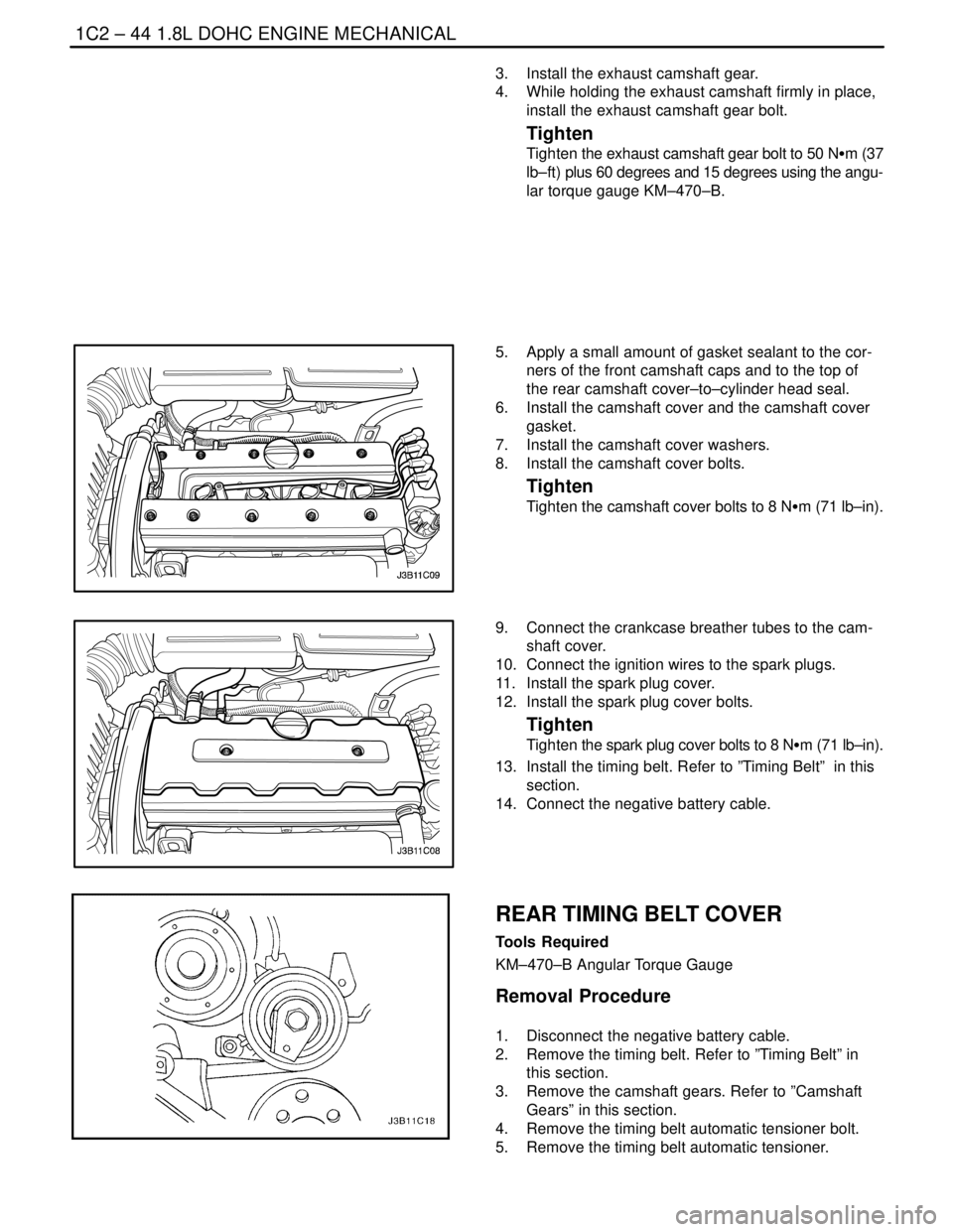
5. Apply a small amount of gasket sealant to the cor-
ners of the front camshaft caps and to the top of
the rear camshaft cover–to–cylinder head seal.
6. Install the camshaft cover and the camshaft cover
gasket.
7. Install the camshaft cover washers.
8. Install the camshaft cover bolts.
Tighten
Tighten the camshaft cover bolts to 8 NSm (71 lb–in).
9. Connect the crankcase breather tubes to the cam-
shaft cover.
10. Connect the ignition wires to the spark plugs.
11. Install the spark plug cover.
12. Install the spark plug cover bolts.
Tighten
Tighten the spark plug cover bolts to 8 NSm (71 lb–in).
13. Install the timing belt. Refer to ”Timing Belt” in this
section.
14. Connect the negative battery cable.
REAR TIMING BELT COVER
Tools Required
KM–470–B Angular Torque Gauge
Removal Procedure
1. Disconnect the negative battery cable.
2. Remove the timing belt. Refer to ”Timing Belt” in
this section.
3. Remove the camshaft gears. Refer to ”Camshaft
Gears” in this section.
4. Remove the timing belt automatic tensioner bolt.
5. Remove the timing belt automatic tensioner.