2004 DAEWOO NUBIRA check engine
[x] Cancel search: check enginePage 2498 of 2643

9T2 – 8IIMMOBILIZER ANTI–THEFT SYSTEM
DAEWOO V–121 BL4
KEY STATUS ERRORS (MR–140,
HV–240, SIRIUS D4)
The following KEY STATUS messages may be shown on
the scan tool after commanding FIRST KEY CODING and
KEY ADD:
S IGNITION OFF STATUS. This message informs
the technician that the ignition is off during the key
coding process. Turn the ignition ON during key
coding, but do not start the engine.
S KEY IS OCCUPIED. Only five keys may be coded.
If a new key is desired, the previous key codes
must be deleted. Up to five keys may then be au-
thorized.
S ALREADY AUTHORIZED. Key coding is being at-
tempted with a key that is already authorized.
S ERROR NO. A3, A4, A5. There is no communica-
tion between the transponder in the ignition key and
the detection coil. Follow the steps below to diag-
nose the problem:
1) Try a different key. If a different key works, the
problem was in the original key.
2) If trying a different key resulted in the same
error message, replace the detection coil.
S INVALID KEY. The communication between the
immobilizer control unit and the key transponder
has not validated the key. Follow the steps below to
diagnose the problem:
1) Code the key. Refer to ”Key Coding Procedure”
in this section.
2) If the same message is received after key cod-
ing, check the connection of the detection coil.
3) If the detection coil is okay, replace the immo-
bilizer. Refer to ”Immobilizer Control Unit” in
this section.S NO TRANSPONDER DETECTED. The fault may
be in ignition key transponder, the detection coil, or
the Immobilizer. Follow the steps below to diagnose
the problem:
1) Try a different key. If a different key works, the
problem was in the original key.
2) If trying a different key resulted in the same
error message, check the connection of the
detection coil.
3) If the connection of the detection coil is okay,
disconnect the detection coil and use an ohm-
meter to check for an open detection coil.
4) If the detection coil was not open, replace the
immobilizer control unit. Refer to ”Immobilizer
Control Unit” in this section.
COMMUNICATION BETWEEN
IMMOBILIZER CONTROL UNIT AND
TEST EQUIPMENT (MR–140, HV–240,
SIRIUS D4)
1. Connect the test equipment as described in the
Scan Tool Equipment Manual.
2. If communication between the scan tool and the
test equipment was unsuccessful, wait 30 seconds
and try again.
3. If communication was not successful on the second
try, turn the ignition OFF and check the wire and
connectors between the immobilizer control unit
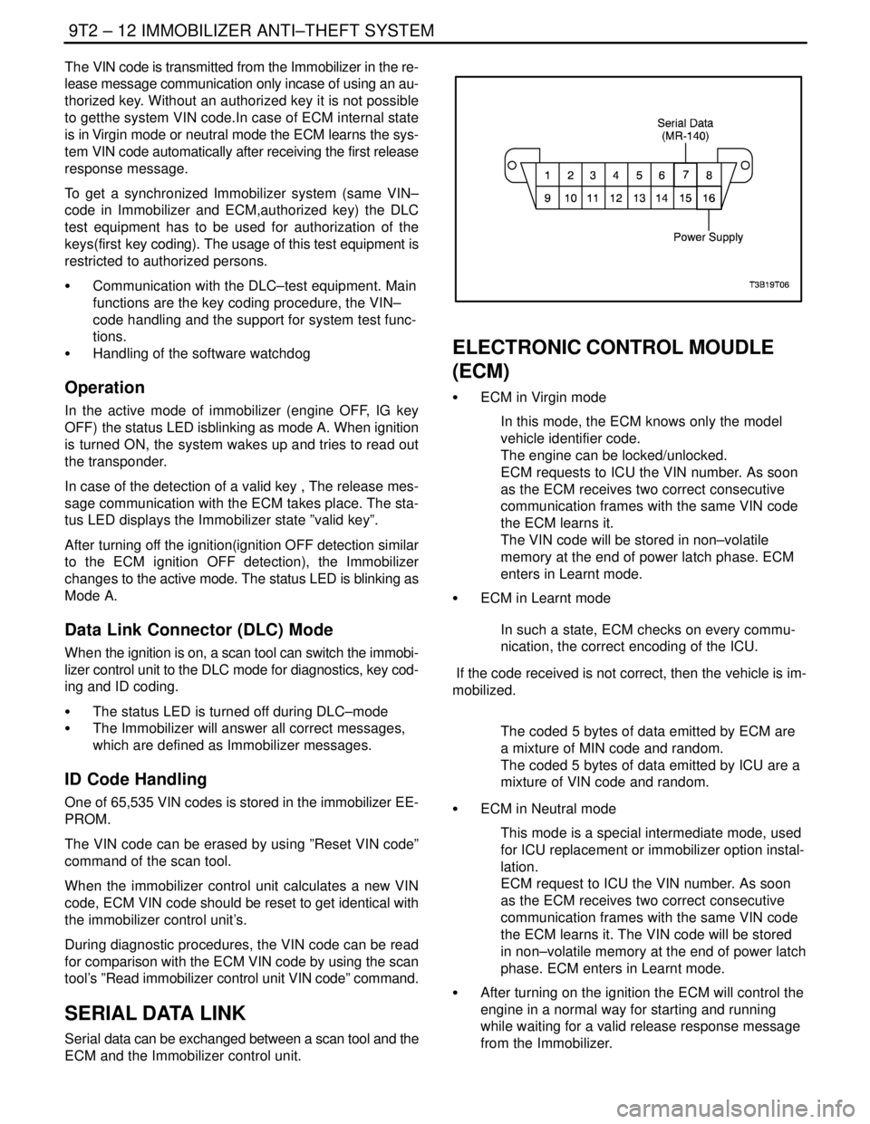
terminal 7 and the data link connector (DLC) termi-
nal 7.
4. If the wire and connectors between the DLC and
the immobilizer control unit are okay, replace the
immobilizer control unit. Refer to ”Immobilizer Con-
trol Unit” in this section.
Page 2502 of 2643

9T2 – 12IIMMOBILIZER ANTI–THEFT SYSTEM
DAEWOO V–121 BL4
The VIN code is transmitted from the Immobilizer in the re-
lease message communication only incase of using an au-
thorized key. Without an authorized key it is not possible
to getthe system VIN code.In case of ECM internal state
is in Virgin mode or neutral mode the ECM learns the sys-
tem VIN code automatically after receiving the first release
response message.
To get a synchronized Immobilizer system (same VIN–
code in Immobilizer and ECM,authorized key) the DLC
test equipment has to be used for authorization of the
keys(first key coding). The usage of this test equipment is
restricted to authorized persons.
S Communication with the DLC–test equipment. Main
functions are the key coding procedure, the VIN–
code handling and the support for system test func-
tions.
S Handling of the software watchdog
Operation
In the active mode of immobilizer (engine OFF, IG key
OFF) the status LED isblinking as mode A. When ignition
is turned ON, the system wakes up and tries to read out
the transponder.
In case of the detection of a valid key , The release mes-
sage communication with the ECM takes place. The sta-
tus LED displays the Immobilizer state ”valid key”.
After turning off the ignition(ignition OFF detection similar
to the ECM ignition OFF detection), the Immobilizer
changes to the active mode. The status LED is blinking as
Mode A.
Data Link Connector (DLC) Mode
When the ignition is on, a scan tool can switch the immobi-
lizer control unit to the DLC mode for diagnostics, key cod-
ing and ID coding.
S The status LED is turned off during DLC–mode
S The Immobilizer will answer all correct messages,
which are defined as Immobilizer messages.
ID Code Handling
One of 65,535 VIN codes is stored in the immobilizer EE-
PROM.
The VIN code can be erased by using ”Reset VIN code”
command of the scan tool.
When the immobilizer control unit calculates a new VIN
code, ECM VIN code should be reset to get identical with
the immobilizer control unit’s.
During diagnostic procedures, the VIN code can be read
for comparison with the ECM VIN code by using the scan
tool’s ”Read immobilizer control unit VIN code” command.
SERIAL DATA LINK
Serial data can be exchanged between a scan tool and the
ECM and the Immobilizer control unit.
ELECTRONIC CONTROL MOUDLE
(ECM)
S ECM in Virgin mode
In this mode, the ECM knows only the model
vehicle identifier code.
The engine can be locked/unlocked.
ECM requests to ICU the VIN number. As soon
as the ECM receives two correct consecutive
communication frames with the same VIN code
the ECM learns it.
The VIN code will be stored in non–volatile
memory at the end of power latch phase. ECM
enters in Learnt mode.
S ECM in Learnt mode
In such a state, ECM checks on every commu-
nication, the correct encoding of the ICU.
If the code received is not correct, then the vehicle is im-
mobilized.
The coded 5 bytes of data emitted by ECM are
a mixture of MIN code and random.
The coded 5 bytes of data emitted by ICU are a
mixture of VIN code and random.
S ECM in Neutral mode
This mode is a special intermediate mode, used
for ICU replacement or immobilizer option instal-
lation.
ECM request to ICU the VIN number. As soon
as the ECM receives two correct consecutive
communication frames with the same VIN code
the ECM learns it. The VIN code will be stored
in non–volatile memory at the end of power latch
phase. ECM enters in Learnt mode.
S After turning on the ignition the ECM will control the
engine in a normal way for starting and running
while waiting for a valid release response message
from the Immobilizer.
Page 2524 of 2643

2–4 PREPARATIONS OF BODYWORK NUBIRA/LACETTI
2. CHECKPOINTS
S Accurate Inspection of Damaged Parts(Visual)
.
Seat Belts
Always replace the seat belt if :
1. The belt material is cut, punctured, burned or in any
way damaged.
2. The buckle or retractor does not work properly.
3. They were being worn at the time of a collision(also
check for damage at the seat belt anchor points).
4. Their condition is questionable.
.
Front Section :
1. Is there any bending, splitting, denting or other dam-
age to the suspension and its related parts?
2. Is there any deformation of the front panel or radiator
crossmember? Have any of the connected sections
come apart?
3. Are there any creases or distortion in the front wheel-
house or side frame? Have any of the connected sec-
tions come apart?
4. Is there any bending or twisting of the whole front
area?
5. Is there any deformation like creases, bulges, or dents
in the front pillar, dash panel, floor, etc.?
6. Is there any vertical twisting or misaligned clearance
in the door?
7. Is the windshield seal broken?
8. Is there any deformation in the vicinity of the top part
of the roof panel’s center pillar?
9. Is there any damage inside the automobile(is there
any twisting of the dash panel, or anything irregular with
the clearances or sheet–mounting parts)?
10. Is there any damage to the steering wheel? Is there
any deformation in the column and the column–mounted
parts?
11. Is there any oil or water leakage and damage to the en-
gine, transmission or brakes?
12. Is there any irregular noise in the gear changing opera-
tion, engine and transmission rotation?
13. Are there any traces of contact between the engine
block and the center crossmember ?
14. Is there any damage to brake or fuel lines, or wire har-
nesses?Rear Section :
1. Is there any twisting, bulging or denting of the rear floor
any rear bolsters? Have any of the connected sections
come apart?
2. Is there any irregular bulging or denting in the rear
fender?
3. Is there any distortion in the rear inner panel? Is there
any bending and denting in the vicinity of the rear pillar?
4. Is there any distortion or creasing is the rear wheel-
house and arch sections? Have any of the connected
sections come apart?
5. Is there anything irregular in the rear glass seal clear-
ance?
6. Is there any twisting or misalignment of the clearance
of the trunk lid opening section?
7. Is there any bending, splitting, denting or other dam-
age to the suspension and its related parts?
8. Is there any deformation of the rear floor crossmem-
ber, trunk floor panel and back panel? Have any of the
connected sections come apart?
.
Impact Beam :
Always replace the door assembly if :
1. The external force makes the impact beam of door in-
ner deform.
Always replace impact beam if :
2. The external force makes the impact beam of front
bumper and rear bumper deform.
Page 2537 of 2643

NUBIRA/LACETTIFRONT 4–3
1–2. REPAIR PROCEDURE
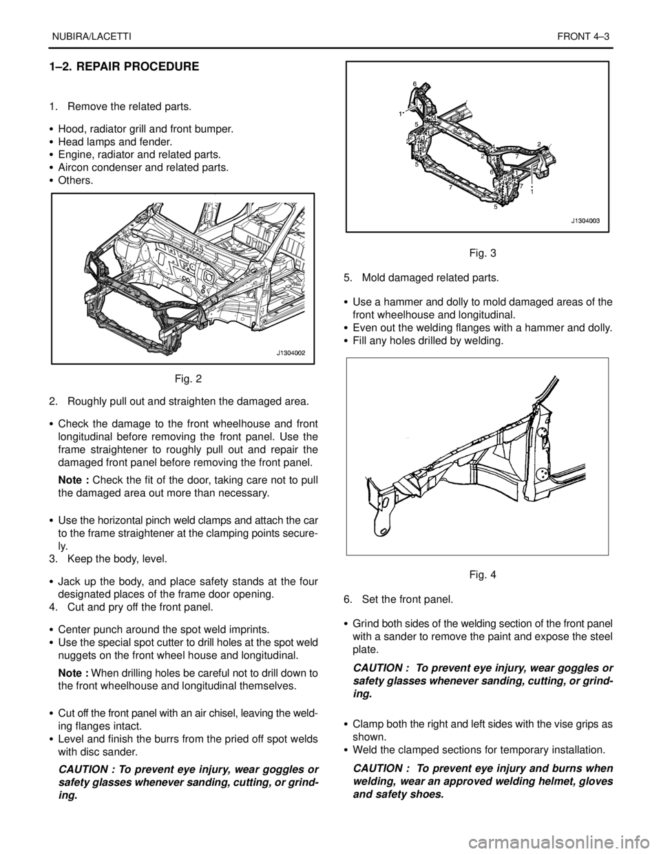
1. Remove the related parts.
S Hood, radiator grill and front bumper.
S Head lamps and fender.
S Engine, radiator and related parts.
S Aircon condenser and related parts.
S Others.
Fig. 2
2. Roughly pull out and straighten the damaged area.
S Check the damage to the front wheelhouse and front
longitudinal before removing the front panel. Use the
frame straightener to roughly pull out and repair the
damaged front panel before removing the front panel.
Note : Check the fit of the door, taking care not to pull
the damaged area out more than necessary.
S Use the horizontal pinch weld clamps and attach the car
to the frame straightener at the clamping points secure-
ly.
3. Keep the body, level.
S Jack up the body, and place safety stands at the four
designated places of the frame door opening.
4. Cut and pry off the front panel.
S Center punch around the spot weld imprints.
S Use the special spot cutter to drill holes at the spot weld
nuggets on the front wheel house and longitudinal.
Note : When drilling holes be careful not to drill down to
the front wheelhouse and longitudinal themselves.
S Cut off the front panel with an air chisel, leaving the weld-
ing flanges intact.
S Level and finish the burrs from the pried off spot welds
with disc sander.
CAUTION : To prevent eye injury, wear goggles or
safety glasses whenever sanding, cutting, or grind-
ing.
Fig. 3
5. Mold damaged related parts.
S Use a hammer and dolly to mold damaged areas of the
front wheelhouse and longitudinal.
S Even out the welding flanges with a hammer and dolly.
S Fill any holes drilled by welding.
Fig. 4
6. Set the front panel.
S Grind both sides of the welding section of the front panel
with a sander to remove the paint and expose the steel
plate.
CAUTION : To prevent eye injury, wear goggles or
safety glasses whenever sanding, cutting, or grind-
ing.
S Clamp both the right and left sides with the vise grips as
shown.
S Weld the clamped sections for temporary installation.
CAUTION : To prevent eye injury and burns when
welding, wear an approved welding helmet, gloves
and safety shoes.
Page 2538 of 2643

4–4 FRONTNUBIRA/LACETTI
Fig. 5
Note : Make sure that the right and left front panels are
in line with each others.
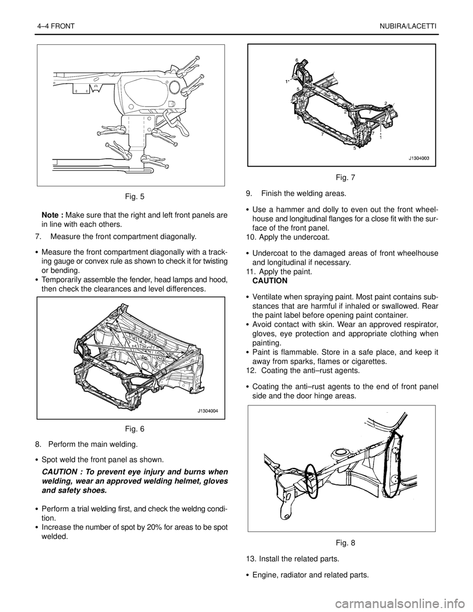
7. Measure the front compartment diagonally.
S Measure the front compartment diagonally with a track-
ing gauge or convex rule as shown to check it for twisting
or bending.
S Temporarily assemble the fender, head lamps and hood,
then check the clearances and level differences.
Fig. 6
8. Perform the main welding.
S Spot weld the front panel as shown.
CAUTION : To prevent eye injury and burns when
welding, wear an approved welding helmet, gloves
and safety shoes.
S Perform a trial welding first, and check the weldng condi-
tion.
S Increase the number of spot by 20% for areas to be spot
welded.
Fig. 7
9. Finish the welding areas.
S Use a hammer and dolly to even out the front wheel-
house and longitudinal flanges for a close fit with the sur-
face of the front panel.
10. Apply the undercoat.
S Undercoat to the damaged areas of front wheelhouse
and longitudinal if necessary.
11. Apply the paint.
CAUTION
S Ventilate when spraying paint. Most paint contains sub-
stances that are harmful if inhaled or swallowed. Rear
the paint label before opening paint container.
S Avoid contact with skin. Wear an approved respirator,
gloves, eye protection and appropriate clothing when
painting.
S Paint is flammable. Store in a safe place, and keep it
away from sparks, flames or cigarettes.
12. Coating the anti–rust agents.
S Coating the anti–rust agents to the end of front panel
side and the door hinge areas.
Fig. 8
13. Install the related parts.
S Engine, radiator and related parts.
Page 2546 of 2643

4–12 FRONTNUBIRA/LACETTI
Note : Use of jigs is recommended for correct positions
and check that the both front longitudinal and wheel-
house are parallel.
S Tack weld the clamped section for temporary installa-
tion.
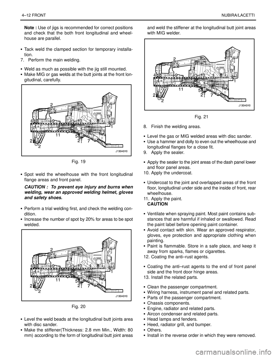
7. Perform the main welding.
S Weld as much as possible with the jig still mounted.
S Make MIG or gas welds at the butt joints at the front lon-
gitudinal, carefully.
Fig. 19
S Spot weld the wheelhouse with the front longitudinal
flange areas and front panel.
CAUTION : To prevent eye injury and burns when
welding, wear an approved welding helmet, gloves
and safety shoes.
S Perform a trial welding first, and check the welding con-
dition.
S Increase the number of spot by 20% for areas to be spot
welded.
Fig. 20
S Level the weld beads at the longitudinal butt joints area
with disc sander.
S Make the stiffener(Thickness: 2.8 mm Min., Width: 80
mm) according to the form of longitudinal butt joint areasand weld the stiffener at the longitudinal butt joint areas
with MIG welder.
Fig. 21
8. Finish the welding areas.
S Level the gas or MIG welded areas with disc sander.
S Use a hammer and dolly to even out the wheelhouse and
longitudinal flanges for a close fit.
9. Apply the sealer.
S Apply the sealer to the joint areas of the dash panel lower
and floor panel areas.
10. Apply the undercoat.
S Undercoat to the joint and overlapped areas of the front
floor, longitudinal under side and the inside of front, rear
wheelhouse.
11. Apply the paint.
CAUTION
S Ventilate when spraying paint. Most paint contains sub-
stances that are harmful if inhaled or swallowed. Read
the paint label before opening paint container.
S Avoid contact with skin. Wear an approved respirator,
gloves, eye protection and appropriate clothing when
painting.
S Paint is flammable. Store in a safe place, and keep it
away from sparks, flames or cigarettes.
12. Coating the anti–rust agents.
S Coating the anti–rust agents to the end of front panel
side and the front door hinge areas.
13. Install the related parts.
S Clean the passenger compartment.
S Wiring harness, instrument panel and related parts.
S Parts of the passenger compartment.
S Chassis components.
S Engine, radiator and related parts.
S Aircon condenser and related parts.
S Head lamps and fenders.
S Heed, radiator grill, and bumper.
S Others.
S Install in the reverse order in which they were removed.