Page 1823 of 2643
AISIN AUTOMATIC TRANSAXLE 5A2 – 233
DAEWOO V–121 BL4
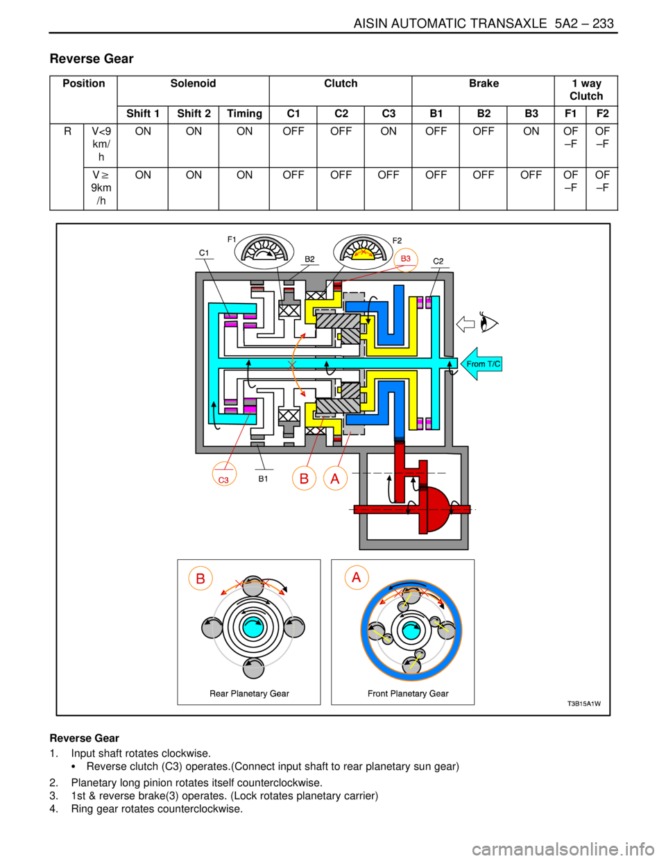
Reverse Gear
PositionSolenoidClutchBrake1 way
Clutch
Shift 1Shift 2TimingC1C2C3B1B2B3F1F2
RV<9
km/
hONONONOFFOFFONOFFOFFONOF
–FOF
–F
V�
9km
/hONONONOFFOFFOFFOFFOFFOFFOF
–FOF
–F
Reverse Gear
1. Input shaft rotates clockwise.
S Reverse clutch (C3) operates.(Connect input shaft to rear planetary sun gear)
2. Planetary long pinion rotates itself counterclockwise.
3. 1st & reverse brake(3) operates. (Lock rotates planetary carrier)
4. Ring gear rotates counterclockwise.
Page 1824 of 2643
5A2 – 234IAISIN AUTOMATIC TRANSAXLE
DAEWOO V–121 BL4
5. Counter drive gear rotates counterclockwise for ring gear and one.
6. Counter driven gear rotates clockwise.
7. Differential gear drive pinion rotates clockwise for counter driven gear and one.
8. Differential gear rotates counterclockwise.
(Engine Brake)
Driving force is connected to input shaft directory without 1 way clutch.
Therefore Engine Brake operates.
Page 1825 of 2643

SECTION : 5B
FIVE–SPEED MANUAL TRANSAXLE
CAUTION : Disconnect the negative battery cable before removing or installing any electrical unit or when a tool
or equipment could easily come in contact with exposed electrical terminals. Disconnecting this cable will help
prevent personal injury and damage to the vehicle. The ignition must also be in LOCK unless otherwise noted.
TABLE OF CONTENTS
SPECIFICATIONS5B–2 . . . . . . . . . . . . . . . . . . . . . . . . . .
Fastener Tightening Specifications 5B–2. . . . . . . . . . .
SPECIAL TOOLS5B–3 . . . . . . . . . . . . . . . . . . . . . . . . . . .
Special Tools Table 5B–3. . . . . . . . . . . . . . . . . . . . . . . .
DIAGNOSIS5B–5 . . . . . . . . . . . . . . . . . . . . . . . . . . . . . . . .
Isolate Noise 5B–5. . . . . . . . . . . . . . . . . . . . . . . . . . . . . .
Symptom Diagnosis 5B–6. . . . . . . . . . . . . . . . . . . . . . . .
COMPONENT LOCATORS5B–9 . . . . . . . . . . . . . . . . . .
Gears and Case 5B–9. . . . . . . . . . . . . . . . . . . . . . . . . . .
Bearing Plate 5B–11. . . . . . . . . . . . . . . . . . . . . . . . . . . .
Differential Gear 5B–12. . . . . . . . . . . . . . . . . . . . . . . . . .
Shift Linkage 5B–13. . . . . . . . . . . . . . . . . . . . . . . . . . . . .
MAINTENANCE AND REPAIR5B–15 . . . . . . . . . . . . . .
ON–VEHICLE SERVICE 5B–15. . . . . . . . . . . . . . . . . . . .
Checking Fluid Level 5B–15. . . . . . . . . . . . . . . . . . . . . .
Shift Linkage Adjustment 5B–15. . . . . . . . . . . . . . . . . . Gearshift Lever 5B–17. . . . . . . . . . . . . . . . . . . . . . . . . . .
Gearshift Lever Housing 5B–18. . . . . . . . . . . . . . . . . . .
Speedometer Driven Gear 5B–18. . . . . . . . . . . . . . . . .
Shift Linkage Assembly 5B–19. . . . . . . . . . . . . . . . . . . .
Drive Axle Seal 5B–20. . . . . . . . . . . . . . . . . . . . . . . . . . .
Transaxle Assembly 5B–21. . . . . . . . . . . . . . . . . . . . . . .
UNIT REPAIR 5B–26. . . . . . . . . . . . . . . . . . . . . . . . . . . . .
Major Component Disassembly 5B–26. . . . . . . . . . . . .
Input Shaft and Cluster Gear 5B–35. . . . . . . . . . . . . . .
Mainshaft 5B–37. . . . . . . . . . . . . . . . . . . . . . . . . . . . . . . .
Housing Case 5B–48. . . . . . . . . . . . . . . . . . . . . . . . . . . .
Differential 5B–50. . . . . . . . . . . . . . . . . . . . . . . . . . . . . . .
Major Component Assembly 5B–56. . . . . . . . . . . . . . .
GENERAL DESCRIPTION AND SYSTEM
OPERATION5B–63 . . . . . . . . . . . . . . . . . . . . . . . . . . . . .
Five–Speed Manual Transaxle 5B–63. . . . . . . . . . . . . .
Page 1826 of 2643

5B – 2IFIVE–SPEED MANUAL TRANSAXLE
DAEWOO V–121 BL4
SPECIFICATIONS
FASTENER TIGHTENING SPECIFICATIONS
ApplicationNSmLb–FtLb–In
Backup Lamp Switch2015–
Bearing Plate Bolts2216–
Bearing Retainer Bolts, Right Side2518–
Bearing–Adjusting Ring–Retainer Plate Bolt5–44
Clutch–Release Cylinder Retaining Bolts2015–
Damping Block Connection Nut and Bolt6850–
Differential Cover Bolts4030–
Fifth–Gear Fork Bolts2216–
Fifth–Gearshift Connector Bolts7–62
Flywheel Inspection Cover Bolts7–62
Gearshift Housing Bolts7–62
Gearshift Lever Cover Bolts2216–
Input Driveshaft Detent Screw1511–
Rear Damping Block Retaining Bolts6850–
Rear Mounting Bracket Bolts9066–
Ring–Gear Bolts7052–
Rod Clamp Bolt14–124
Speedometer Housing Retaining Bolt4–35
Speedometer–Driven Gear Bolt5–44
Transaxle Cover Bolts1813–
Transaxle Lower Retaining Bolts(a)7354–
Transaxle Lower Retaining Bolt(b)3123–
Transaxle Lower Retaining Bolts(c)2115–
Transaxle Upper Retaining Bolts7354–
Transaxle Upper Mounting Bracket Bolts4835–
Page 1829 of 2643

FIVE–SPEED MANUAL TRANSAXLE 5B – 5
DAEWOO V–121 BL4
DIAGNOSIS
ISOLATE NOISE
Identify the cause of any noise before attempting to repair
the clutch, the transaxle, or their related link–ages.
Symptoms of trouble with the clutch or the manual trans-
axle include:
S A great effort required to shift gears.
S The sound of gears clashing and grinding.
S Gear blockout.
Any of these conditions requires a careful analysis. Make
the following checks before disassembling the clutch or
the transaxle for repairs.
Road Travel Noise
Many noises that appear to come from the transaxle may
actually originate with other sources such as the:
S Tires.
S Road surfaces.
S Wheel bearings.
S Engine.
S Exhaust system.
These noises may vary according to the:
S Size of the vehicle.
S Type of the vehicle.
S Amount of insulation used in the body of the ve-
hicle.
Transaxle Noise
Transaxle gears, like any mechanical device, are not ab-
solutely quiet and will make some noise during normal op-
eration.
To verify suspected transaxle noises:
1. Select a smooth, level asphalt road to reduce tire
and resonant body noise.
2. Drive the vehicle far enough to warm up all the lu-
bricants thoroughly.
3. Record the speed and the gear range of the trans-
axle when the noise occurs.
4. Check for noises with the vehicle stopped, but with
the engine running.
5. Determine if the noise occurs while the vehicle op-
erates in:
S Drive – under a light acceleration or a heavy
pull.
S Float – maintaining a constant speed with a light
throttle on a level road.
S Coast – with the transaxle in gear and the
throttle partly or fully closed.
S All of the above.
Bearing Noise
Differential Side Bearing Noise
Differential side bearing noise and wheel bearing noise
can be confused easily. Since side bearings are pre–
loaded, a differential side bearing noise should not dimin-
ish much when the differential/transaxle is run with the
wheels off the ground.
Wheel Bearing Noise
Wheel bearings produce a rough growl or grating sound
that will continue when the vehicle is coasting and the
transaxle is in NEUTRAL. Since wheel bearings are not
pre–loaded, a wheel bearing noise should diminish con-
siderably when the wheels are off the ground.
Other Noise
Brinelling
A brinelled bearing causes a ”knock” or ”click” approxi-
mately every second revolution of the wheel because the
bearing rollers do not travel at the same speed as the
wheel. In operation, the effect is characterized by a low–
pitched noise.
A brinelled bearing is caused by excessive thrust which
pushes the balls up on the pathway and creates a triangu-
lar–shaped spot in the bearing race. A brinelled bearing
can also be caused from pressing one race into position
by applying pressure on the other race.
A false indication of a brinelled bearing occurs as a result
of vibration near the area where the bearing is mounted.
Brinelling is identified by slight indentations, resulting in a
washboard effect in the bearing race.
Lapping
Lapped bearing noise occurs when fine particles of abra-
sive materials such as scale, sand, or emery circulate
through the oil in the vehicle, causing the surfaces of the
roller and the race to wear away. Bearings that wear loose
but remain smooth, without spalling or pitting, are the re-
sult of dirty oil.
Locking
Large particles of foreign material wedged between the
roller and the race usually causes one of the races to turn,
creating noise from a locked bearing. Pre–loading regular
taper roller bearings to a value higher than that specified
also can result in locked bearings
Pitting
Pitting on the rolling surface comes from normal wear and
the introduction of foreign materials.
Spalling
Spalled bearings have flaked or pitted rollers or races
caused by an overload or an incorrect assembly that re-
sults in a misalignment, a cocking of bearings, or adjust-
ments that are too tight.
After completing these checks, refer to the ”Diagnosis
Chart” in this section.
Page 1835 of 2643
FIVE–SPEED MANUAL TRANSAXLE 5B – 11
DAEWOO V–121 BL4
BEARING PLATE
1. Strain Bolt Bridge
2. Bolt
3. Bolt
4. Bolt
5. Bearing Plate
6. Bolt
7. Pin
8. Blocking Pin
9. Compression Spring
10. Plug
11. Gear Shift Sliding Fork12. GearShift Shoe
13. Screw
14. Transaxle Cover
15. Transaxle Cover Gasket
16. Magnet
17. Bearing Plate Gasket
18. Bolt
19. Bolt
20. Bolt
21. Screw
22. Detent Sleeve
Page 1836 of 2643
5B – 12IFIVE–SPEED MANUAL TRANSAXLE
DAEWOO V–121 BL4
DIFFERENTIAL GEAR
1. Differential Gear Housing
2. Differential Gear
3. Speedometer Drive Gear
4. Washer
5. Side Gear
6. Bevel Differential Gear
7. Bevel Gear Disc
8. Differential Gear Shaft
9. Differential Spring Pin
10. Bolt11. Taper Roller Bearing
12. Differential Bearing Ring
13. Shaft Seal Ring
14. O–Ring
15. Differential Gear Bearing Flange
16. O–Ring
17. Locking Plate
18. Bolt
19. Bolt
Page 1845 of 2643
FIVE–SPEED MANUAL TRANSAXLE 5B – 21
DAEWOO V–121 BL4
TRANSAXLE ASSEMBLY
Tools Required
J–28467–B Engine Support Fixture
Removal Procedure
1. Install the engine support fixture J–28467–B.
2. Remove the battery and battery tray. Refer to Sec-
tion 1E, ENGINE ELETRICAL.
3. Remove the shift linkage assembly. Refer to ”Shift
Linkage Adjustment” in this section.
4. Remove the drive axle shaft. Refer to Section 3B,
Manual Transaxle Drive Axle.
5. Disconnect the backup lamp switch electrical con-
nector.
6. Disconnect the speedometer speed sensor electri-
cal connector.
7. Remove the pin and the clutch release cylinder
pipe.
8. Remove the damping block connection nut and
bolt.
9. Remove the three rear mounting bracket bolts.
10. Remove the rear mounting bracket from the trans-
axle.