2004 DAEWOO NUBIRA suspension
[x] Cancel search: suspensionPage 966 of 2643
2E – 4ITIRES AND WHEELS
DAEWOO V–121 BL4
ON–VEHICLE BALANCING
On–vehicle balancing will help correct vibrations due to
brake drum, rotor, and wheel cover imbalances.
Notice : Do not allow the front suspension to hang free.
When the drive axle is run at an extreme angle, extra vibra-
tions can occur, as well as damage to seals and joints.
1. During on–vehicle balancing, do not remove the
balance weights from the off–vehicle dynamic bal-
ance.
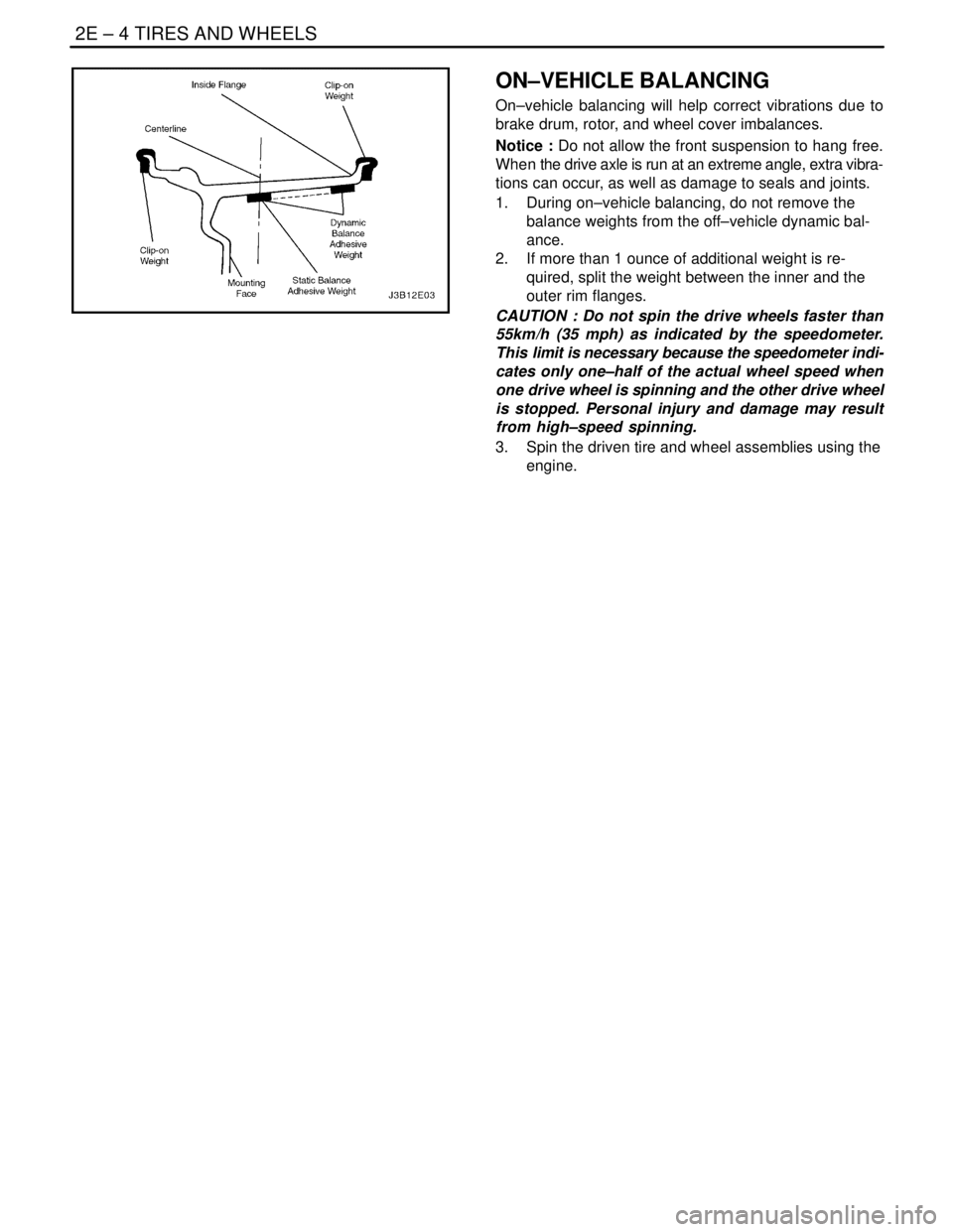
2. If more than 1 ounce of additional weight is re-
quired, split the weight between the inner and the
outer rim flanges.
CAUTION : Do not spin the drive wheels faster than
55km/h (35 mph) as indicated by the speedometer.
This limit is necessary because the speedometer indi-
cates only one–half of the actual wheel speed when
one drive wheel is spinning and the other drive wheel
is stopped. Personal injury and damage may result
from high–speed spinning.
3. Spin the driven tire and wheel assemblies using the
engine.
Page 1929 of 2643
6C – 12IPOWER STEERING GEAR
DAEWOO V–121 BL4
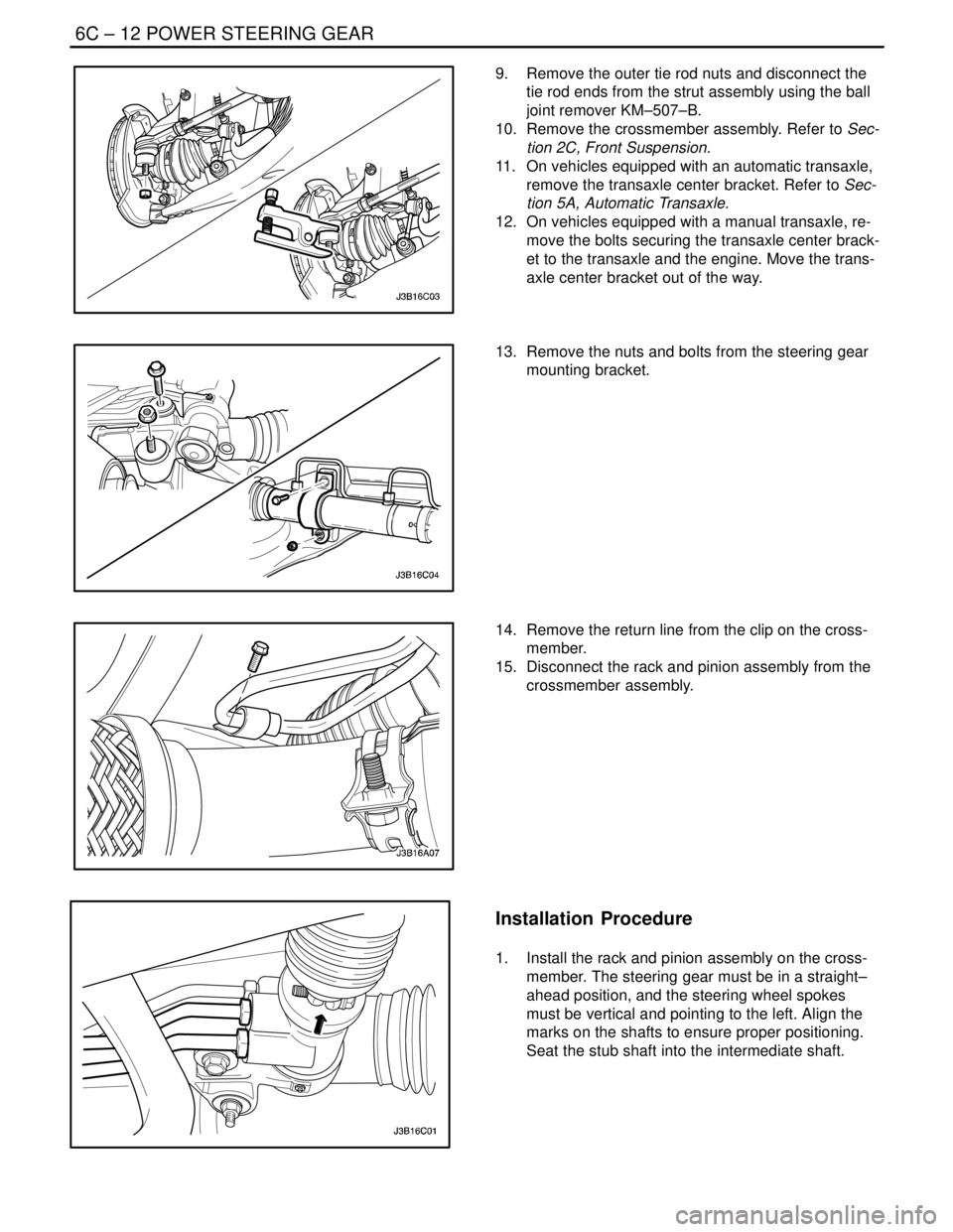
9. Remove the outer tie rod nuts and disconnect the
tie rod ends from the strut assembly using the ball
joint remover KM–507–B.
10. Remove the crossmember assembly. Refer to Sec-
tion 2C, Front Suspension.
11. On vehicles equipped with an automatic transaxle,
remove the transaxle center bracket. Refer to Sec-
tion 5A, Automatic Transaxle.
12. On vehicles equipped with a manual transaxle, re-
move the bolts securing the transaxle center brack-
et to the transaxle and the engine. Move the trans-
axle center bracket out of the way.
13. Remove the nuts and bolts from the steering gear
mounting bracket.
14. Remove the return line from the clip on the cross-
member.
15. Disconnect the rack and pinion assembly from the
crossmember assembly.
Installation Procedure
1. Install the rack and pinion assembly on the cross-
member. The steering gear must be in a straight–
ahead position, and the steering wheel spokes
must be vertical and pointing to the left. Align the
marks on the shafts to ensure proper positioning.
Seat the stub shaft into the intermediate shaft.
Page 1930 of 2643
POWER STEERING GEAR 6C – 13
DAEWOO V–121 BL4
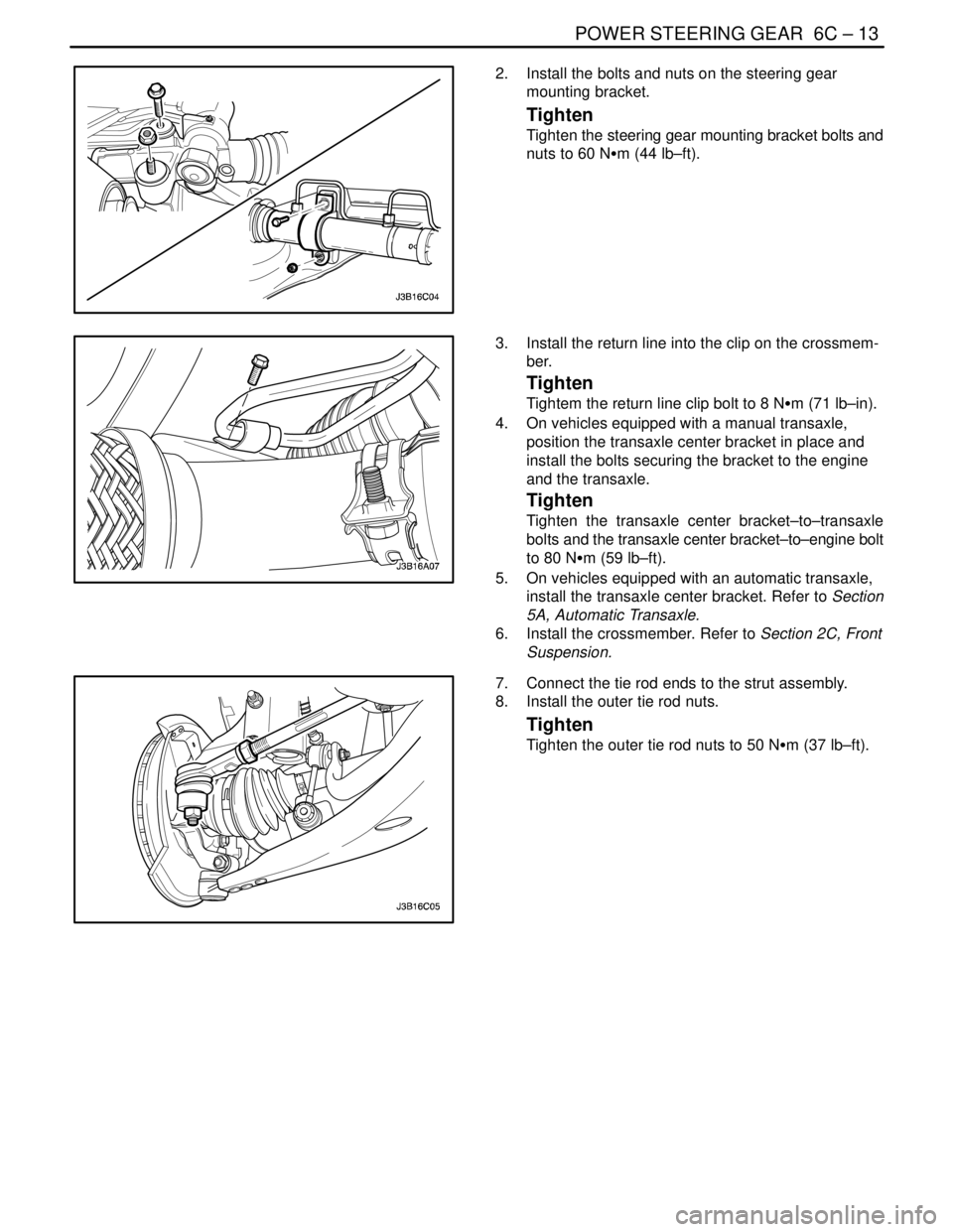
2. Install the bolts and nuts on the steering gear
mounting bracket.
Tighten
Tighten the steering gear mounting bracket bolts and
nuts to 60 NSm (44 lb–ft).
3. Install the return line into the clip on the crossmem-
ber.
Tighten
Tightem the return line clip bolt to 8 NSm (71 lb–in).
4. On vehicles equipped with a manual transaxle,
position the transaxle center bracket in place and
install the bolts securing the bracket to the engine
and the transaxle.
Tighten
Tighten the transaxle center bracket–to–transaxle
bolts and the transaxle center bracket–to–engine bolt
to 80 NSm (59 lb–ft).
5. On vehicles equipped with an automatic transaxle,
install the transaxle center bracket. Refer to Section
5A, Automatic Transaxle.
6. Install the crossmember. Refer to Section 2C, Front
Suspension.
7. Connect the tie rod ends to the strut assembly.
8. Install the outer tie rod nuts.
Tighten
Tighten the outer tie rod nuts to 50 NSm (37 lb–ft).
Page 2377 of 2643

SECTION : 9K
SQUEAKS AND RATTLES
TABLE OF CONTENTS
DIAGNOSIS9K–1 . . . . . . . . . . . . . . . . . . . . . . . . . . . . . . . .
Squeak and Rattle Diagnosis 9K–1. . . . . . . . . . . . . . . .
MAINTENANCE AND REPAIR9K–3 . . . . . . . . . . . . . . . ON–VEHICLE SERVICE 9K–3. . . . . . . . . . . . . . . . . . . . .
Squeak and Rattle Repair 9K–3. . . . . . . . . . . . . . . . . . .
DIAGNOSIS
SQUEAK AND RATTLE DIAGNOSIS
Rattle Coming From the Side Rail
ChecksAction
Check the brake lines.S Tap lightly on the brake lines and listen for a rattle.
S Install plastic tie straps to secure the brake lines
tightly together.
Rattle Under Vehicle at Higher RPM
ChecksAction
Check for heat shield contact with the underbody.S Raise the vehicle and perform a visual inspection.
S Bend the heat shield slightly to gain clearance from
the underbody.
Squeak From the Front of the Vehicle in Cold Weather
ChecksAction
Check the front stabilizer shaft insulators.S While the vehicle is cold, perform a test drive and
achieve full front suspension travel by driving through
a dip in the road.
S Remove the insulators and wrap teflon tape around
the stabilizer shaft. Reinstall the insulators over the
tape.
Thump From Rear of Vehicle on Bumps
ChecksAction
Check for a properly secured spare tire in the rear
compartment.S Open the rear compartment and perform a visual
inspection of the spare tire and the tools.
S Tightly secure the spare tire and all tools.
S Perform a road test to verify that the noise is elimi-
nated.
Page 2409 of 2643

9N – 6IFRAME AND UNDERBODY
DAEWOO V–121 BL4
MAINTENANCE AND REPAIR
ON–VEHICLE SERVICE
ALIGNMENT CHECKING
An accurate method of determining the alignment of the
underbody uses a measuring tram gauge. The tram gauge
set used to perform the recommended measuring checks
must include a vertical pointer able to reach 457 mm (18
inches).
Two types of measurements can be made with a tram
gauge: direct point–to–point measurements and mea-
surements calculated on a horizontal plane (datum line)
parallel to the underbody. Point–to–point measurements
are generally taken on steering and suspension engine
compartment parts and simply require the vertical pointers
to be set equally.
For horizontal plane measurements, the vertical pointers
must be set as specified for each point to be measured.
Dimensions–to–gauge holes are measured to the center
of the holes and flush to the adjacent surface metal unless
otherwise specified. It is recommended that the diagonal
dimensions to the cross–body be checked on both sides
in order to verify the dimensional accuracy of the vehicle
underbody.
FLOOR PAN INSULATORS
The floor pan insulators have been designed for the higher
floor pan temperatures that result from the use of the cata-
lytic converter in the exhaust system. Therefore, when
servicing a vehicle, it is essential that any insulators that
may have been disturbed or removed be reinstalled in the
original sequence and location. Also, if an insulator needs
to be replaced, use only the insulation specified for that
location on the floor pan.
When servicing or replacing interior insulators, observe
the following instructions.
S Install the insulators in the original position and se-
quence. Butt the pieces together in order to avoid
gapping or overlapping.
S If it is necessary to replace an insulator, use only
the specified insulation.
S Use the original part to determine the amount of
replacement material required and as a template for
cutting and fitting the new piece to the floor pan.
S When installing the insulator, do not enlarge any
cutouts or holes that are used for the attachment of
interior parts such as the instrument panel or the
floor console.
S Route the cross–body harness for interior parts
over the floor pan insulators. Clip it in the original
location.
S Do not apply spray–on deadeners or trim adhesives
to the top of the floor pan at the area directly over
the catalytic converter or the muffler.
Page 2411 of 2643

9N – 8IFRAME AND UNDERBODY
DAEWOO V–121 BL4
GENERAL DESCRIPTION
AND SYSTEM OPERATION
GENERAL BODY CONSTRUCTION
This vehicle is constructed with a unitized body which in-
corporates integral front and rear frame side rails.
The front suspension lower control arms are bolted to and
retained by supports, one each on the right and left sides.
The front suspension lower control arm supports are at-
tached to the underbody with three bolts at two locations.
The engine is bolted to the integral front side rails. The
suspension strut towers must be dimensionally correct in
relation to the remainder of the underbody in order to main-
tain specified suspension strut and caster/ camber angles.Since the individual underbody parts contribute directly to
the overall strength of the body, it is essential to observe
proper welding techniques during service repair opera-
tions. The underbody parts should be properly sealed and
rustproofed whenever body repair operations destroy or
damage the original sealing and rustproofing. When rust-
proofing critical underbody parts, use a good–quality type
of air–dry primer, such as a corrosion–resistant chromate
or an equivalent material. Combination–type primer/sur-
facers are not recommended.
ENGINE UNDER COVERS
The engine under covers are molded pieces of plastic that
serve as shields for the underside of the engine. The cov-
ers help protect the engine from small rocks, gravel and
other objects that would otherwise come into contact with
the engine during normal driving conditions.
Page 2524 of 2643

2–4 PREPARATIONS OF BODYWORK NUBIRA/LACETTI
2. CHECKPOINTS
S Accurate Inspection of Damaged Parts(Visual)
.
Seat Belts
Always replace the seat belt if :
1. The belt material is cut, punctured, burned or in any
way damaged.
2. The buckle or retractor does not work properly.
3. They were being worn at the time of a collision(also
check for damage at the seat belt anchor points).
4. Their condition is questionable.
.
Front Section :
1. Is there any bending, splitting, denting or other dam-
age to the suspension and its related parts?
2. Is there any deformation of the front panel or radiator
crossmember? Have any of the connected sections
come apart?
3. Are there any creases or distortion in the front wheel-
house or side frame? Have any of the connected sec-
tions come apart?
4. Is there any bending or twisting of the whole front
area?
5. Is there any deformation like creases, bulges, or dents
in the front pillar, dash panel, floor, etc.?
6. Is there any vertical twisting or misaligned clearance
in the door?
7. Is the windshield seal broken?
8. Is there any deformation in the vicinity of the top part
of the roof panel’s center pillar?
9. Is there any damage inside the automobile(is there
any twisting of the dash panel, or anything irregular with
the clearances or sheet–mounting parts)?
10. Is there any damage to the steering wheel? Is there
any deformation in the column and the column–mounted
parts?
11. Is there any oil or water leakage and damage to the en-
gine, transmission or brakes?
12. Is there any irregular noise in the gear changing opera-
tion, engine and transmission rotation?
13. Are there any traces of contact between the engine
block and the center crossmember ?
14. Is there any damage to brake or fuel lines, or wire har-
nesses?Rear Section :
1. Is there any twisting, bulging or denting of the rear floor
any rear bolsters? Have any of the connected sections
come apart?
2. Is there any irregular bulging or denting in the rear
fender?
3. Is there any distortion in the rear inner panel? Is there
any bending and denting in the vicinity of the rear pillar?
4. Is there any distortion or creasing is the rear wheel-
house and arch sections? Have any of the connected
sections come apart?
5. Is there anything irregular in the rear glass seal clear-
ance?
6. Is there any twisting or misalignment of the clearance
of the trunk lid opening section?
7. Is there any bending, splitting, denting or other dam-
age to the suspension and its related parts?
8. Is there any deformation of the rear floor crossmem-
ber, trunk floor panel and back panel? Have any of the
connected sections come apart?
.
Impact Beam :
Always replace the door assembly if :
1. The external force makes the impact beam of door in-
ner deform.
Always replace impact beam if :
2. The external force makes the impact beam of front
bumper and rear bumper deform.
Page 2544 of 2643

4–10 FRONTNUBIRA/LACETTI
3. FRONT LONGITUDINAL
3–1. GENERAL DESCRIPTION
The front longitudinal is joined to the wheelhouse and
front panel, it forms the base for the front suspension,
engine, transmission and others. Therefore, replace-ment of the component affects the front wheel align-
ment and maintains the rigidity of the front section.
When assembling it, either use a jig or follow dimen-
sions on the body repair chart for positioning. It must be
welded carefully.
Fig. 16 Front Longitudinal Welding Assembly