Page 1819 of 2643
AISIN AUTOMATIC TRANSAXLE 5A2 – 229
DAEWOO V–121 BL4
D–3rd Gear
PositionSolenoidClutchBrake1 way
Clutch
Shift 1Shift 2TimingC1C2C3B1B2B3F1F2
D3rdOFFOFFOFFONONOFFOFFONOFFOF
–FOF
–F
”D” – 3rd Gear
1. Input shaft rotates clockwise.
S Forward clutch (C1) operates. (Connect input shaft to front sun gear)
S Direct clutch (C2) operates. (Connect input shaft to planetary carrier)
2. Planetary short pinion and planetary long pinion can not rotate itself, and planetary gear unit rotates clockwise as
one.
3. Counter drive gear rotates clockwise for ring gear and one.
4. Counter drive gear rotates counterclockwise
Page 1820 of 2643
5A2 – 230IAISIN AUTOMATIC TRANSAXLE
DAEWOO V–121 BL4
5. Differential drive pinion rotates counterclockwise for counter driven gear and one.
6. Differential rotates clockwise.
( Engine Brake)
Driving force is connected to input shaft directory without 1 way clutch.
Therefore Engine Brake operates.
Page 1821 of 2643
AISIN AUTOMATIC TRANSAXLE 5A2 – 231
DAEWOO V–121 BL4
D–4th Gear
PositionSolenoidClutchBrake1 way
Clutch
Shift 1Shift 2TimingC1C2C3B1B2B3F1F2
D4thOFFONOFFOFFONOFFONONOFFOF
–FOF
–F
”D” – 4th Gear
1. Input shaft rotates clockwise.
S Direct clutch (C2) operates. (Connect input shaft to planetary carrier)
2. Planetary carrier revolves clockwise.
3. Planetary long pinion rotates itself clockwise.
4. Rear planetary sun gear is going to rotate counterclockwise.
S O/D & 2nd brake (B1) operates. (Lock rotates planetary sun gear)
5. Planetary long pinion revolves clockwise while rotating itself clockwise.
6. Ring gear rotates clockwise.
7. Counter drive gear rotates clockwise for ring gear and one.
Page 1822 of 2643
5A2 – 232IAISIN AUTOMATIC TRANSAXLE
DAEWOO V–121 BL4
8. Counter driven gear rotates counterclockwise.
9. Differential gear drive pinion rotates counterclockwise for counter driven gear and one.
10. Differential gear rotates clockwise.
( Engine Brake)
Driving force is connected to input shaft directory without 1 way clutch.
Therefore Engine Brake operates.
Page 1823 of 2643
AISIN AUTOMATIC TRANSAXLE 5A2 – 233
DAEWOO V–121 BL4
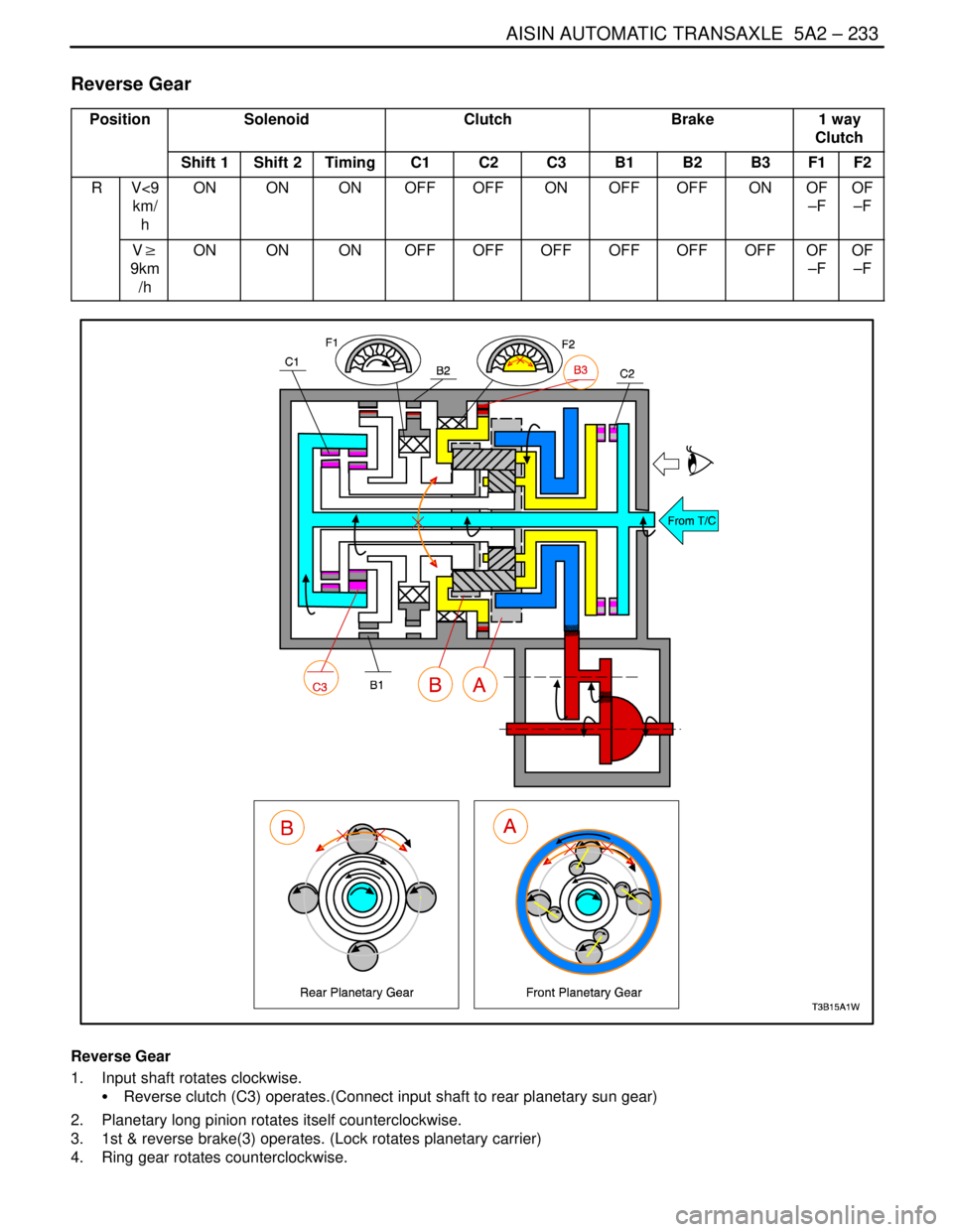
Reverse Gear
PositionSolenoidClutchBrake1 way
Clutch
Shift 1Shift 2TimingC1C2C3B1B2B3F1F2
RV<9
km/
hONONONOFFOFFONOFFOFFONOF
–FOF
–F
V�
9km
/hONONONOFFOFFOFFOFFOFFOFFOF
–FOF
–F
Reverse Gear
1. Input shaft rotates clockwise.
S Reverse clutch (C3) operates.(Connect input shaft to rear planetary sun gear)
2. Planetary long pinion rotates itself counterclockwise.
3. 1st & reverse brake(3) operates. (Lock rotates planetary carrier)
4. Ring gear rotates counterclockwise.
Page 1824 of 2643
5A2 – 234IAISIN AUTOMATIC TRANSAXLE
DAEWOO V–121 BL4
5. Counter drive gear rotates counterclockwise for ring gear and one.
6. Counter driven gear rotates clockwise.
7. Differential gear drive pinion rotates clockwise for counter driven gear and one.
8. Differential gear rotates counterclockwise.
(Engine Brake)
Driving force is connected to input shaft directory without 1 way clutch.
Therefore Engine Brake operates.
Page 1903 of 2643

6A – 2IPOWER STEERING SYSTEM
DAEWOO V–121 BL4
DIAGNOSIS
POWER STEERING SYSTEM
PRESSURE TEST
Tools Required
KM–354–B Pressure Test Gauge Kit
Check the fluid pressure as follows to determine whether
the trouble is in the pump or the gear unit.
Test Procedure
1. Check the power steering fluid level and the power
steering pump belt tension. Refer to ”Checking and
Adding Fluid” in this section and Section 6B, Power
Steering Pump.
2. Disconnect the high pressure line at the pump. Use
a small container to catch any fluid.
3. Connect the hose of the pressure test gauge kit
KM–354–B to the power steering pressure hose
from the power steering pump.
4. Place the gear selector lever in PARK (automatic
transaxle–equipped vehicles) or NEUTRAL (manual
transaxle–equipped vehicles). Set the parking
brake.
5. Open the gauge valve fully.
6. Start the engine and let it idle.
7. Turn the steering wheel from lock to lock several
times to warm the fluid to operating temperature.
8. Increase the engine speed to 1,500 rpm.
Notice : The power steering pump could be damaged if
the valve is fully closed for more than 5 seconds.
9. Close the gauge valve fully, and read the pressure.
The pump pressure with the valve closed should be
between 8,330 kPa to 8,820 kPa (1,208 psi to
1,279 psi). With electronic variable orifice, the pres-
sure should be between 8,500 kPa to 8,960 kPa
(1,233 psi to 1,299 psi).
10. Immediately open the gauge valve fully.
11. Turn the steering wheel all the way to the left and
the right. If the pressure is within the specified lim-
its, the problem is not in the pump. Check the pow-
er steering gear for leaks.
POWER STEERING SYSTEM LEAK
TEST
General Procedure
Inspect the following:
S The fluid reservoir for overfill.
S Fluid for aeration and overflow.
S The hoses for loose connections.
S The torsion bar, stub shaft and adjuster seals for
leaks.
S The component sealing surfaces for damage.
Important : Verify the exact point of the leak. The point
from which the fluid is dripping is not necessarily the point
at which the system is leaking. When service is required,
clean the leak area upon disassembly, replace the leaking
seal, check the component sealing surfaces for damage
and reset the torque bolt to specifications, where required.
External Leak Check
The purpose of this procedure is to pinpoint the location of
the leak. In some cases, the leak can be easily located, but
seepage–type leaks may be harder to find. To locate seep-
age leaks, use the following method:
1. With the engine off, wipe dry the complete power
steering system.
2. Check the power steering fluid level in the pump’s
reservoir. Adjust the fluid level as necessary. Refer
to ”Checking and Adding Fluid” in this section.
Notice : Do not hold the steering wheel at a stop for any
length of time as this can damage the power steering
pump.
3. Start the engine. Turn the steering wheel counter-
clockwise and clockwise from stop to stop several
times.
4. Find the exact area of the leak and repair it.
Page 1929 of 2643

6C – 12IPOWER STEERING GEAR
DAEWOO V–121 BL4
9. Remove the outer tie rod nuts and disconnect the
tie rod ends from the strut assembly using the ball
joint remover KM–507–B.
10. Remove the crossmember assembly. Refer to Sec-
tion 2C, Front Suspension.
11. On vehicles equipped with an automatic transaxle,
remove the transaxle center bracket. Refer to Sec-
tion 5A, Automatic Transaxle.
12. On vehicles equipped with a manual transaxle, re-
move the bolts securing the transaxle center brack-
et to the transaxle and the engine. Move the trans-
axle center bracket out of the way.
13. Remove the nuts and bolts from the steering gear
mounting bracket.
14. Remove the return line from the clip on the cross-
member.
15. Disconnect the rack and pinion assembly from the
crossmember assembly.
Installation Procedure
1. Install the rack and pinion assembly on the cross-
member. The steering gear must be in a straight–
ahead position, and the steering wheel spokes
must be vertical and pointing to the left. Align the
marks on the shafts to ensure proper positioning.
Seat the stub shaft into the intermediate shaft.


Dri")