Page 2457 of 2643

9Q – 8IROOF
DAEWOO V–121 BL4
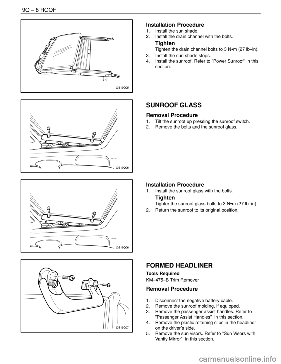
Installation Procedure
1. Install the sun shade.
2. Install the drain channel with the bolts.
Tighten
Tighten the drain channel bolts to 3 NSm (27 lb–in).
3. Install the sun shade stops.
4. Install the sunroof. Refer to ”Power Sunroof” in this
section.
SUNROOF GLASS
Removal Procedure
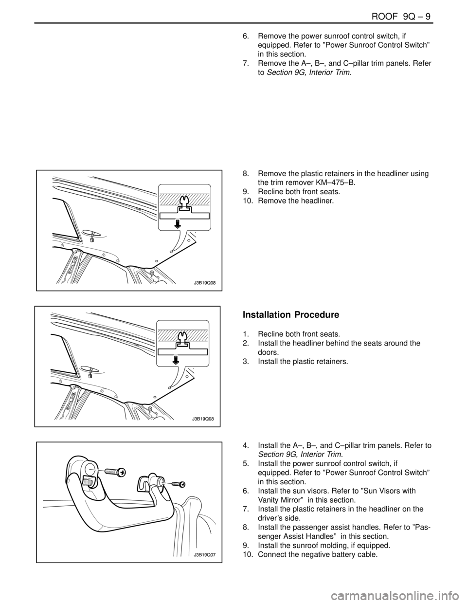
1. Tilt the sunroof up pressing the sunroof switch.
2. Remove the bolts and the sunroof glass.
Installation Procedure
1. Install the sunroof glass with the bolts.
Tighten
Tighter the sunroof glass bolts to 3 NSm (27 lb–in).
2. Return the sunroof to its original position.
FORMED HEADLINER
Tools Required
KM–475–B Trim Remover
Removal Procedure
1. Disconnect the negative battery cable.
2. Remove the sunroof molding, if equipped.
3. Remove the passenger assist handles. Refer to
”Passenger Assist Handles” in this section.
4. Remove the plastic retaining clips in the headliner
on the driver’s side.
5. Remove the sun visors. Refer to ”Sun Visors with
Vanity Mirror” in this section.
Page 2458 of 2643

ROOF 9Q – 9
DAEWOO V–121 BL4
6. Remove the power sunroof control switch, if
equipped. Refer to ”Power Sunroof Control Switch”
in this section.
7. Remove the A–, B–, and C–pillar trim panels. Refer
to Section 9G, Interior Trim.
8. Remove the plastic retainers in the headliner using
the trim remover KM–475–B.
9. Recline both front seats.
10. Remove the headliner.
Installation Procedure
1. Recline both front seats.
2. Install the headliner behind the seats around the
doors.
3. Install the plastic retainers.
4. Install the A–, B–, and C–pillar trim panels. Refer to
Section 9G, Interior Trim.
5. Install the power sunroof control switch, if
equipped. Refer to ”Power Sunroof Control Switch”
in this section.
6. Install the sun visors. Refer to ”Sun Visors with
Vanity Mirror” in this section.
7. Install the plastic retainers in the headliner on the
driver’s side.
8. Install the passenger assist handles. Refer to ”Pas-
senger Assist Handles” in this section.
9. Install the sunroof molding, if equipped.
10. Connect the negative battery cable.
Page 2459 of 2643

9Q – 10IROOF
DAEWOO V–121 BL4
SUN VISORS WITH VANITY MIRROR
Removal Procedure
1. Remove the screws and the sun visor from the
headliner.
2. Disconnect the vanity mirror electrical connector.
Refer to Section 9B, Lighting System.
3. Remove the screw and the sun visor support from
the headliner.
Installation Procedure
Notice : Dissimilar metals in direct contact with each other
may corrode rapidly. Make sure to use the correct fasten-
ers to prevent premature corrosion.
1. Install the sun visor support to the headliner with
the screw.
Tighten
Tighten the sun visor support screw to 1.5 NSm (13 lb–
in).
2. Connect the vanity mirror electrical connector. Re-
fer to Section 9B, Lighting System.
3. Install the sun visor to the headliner with the
screws.
Tighten
Tighten the sun ivsor screws to 4 NSm (35 lb–in).
PASSENGER ASSIST HANDLES
Removal Procedure
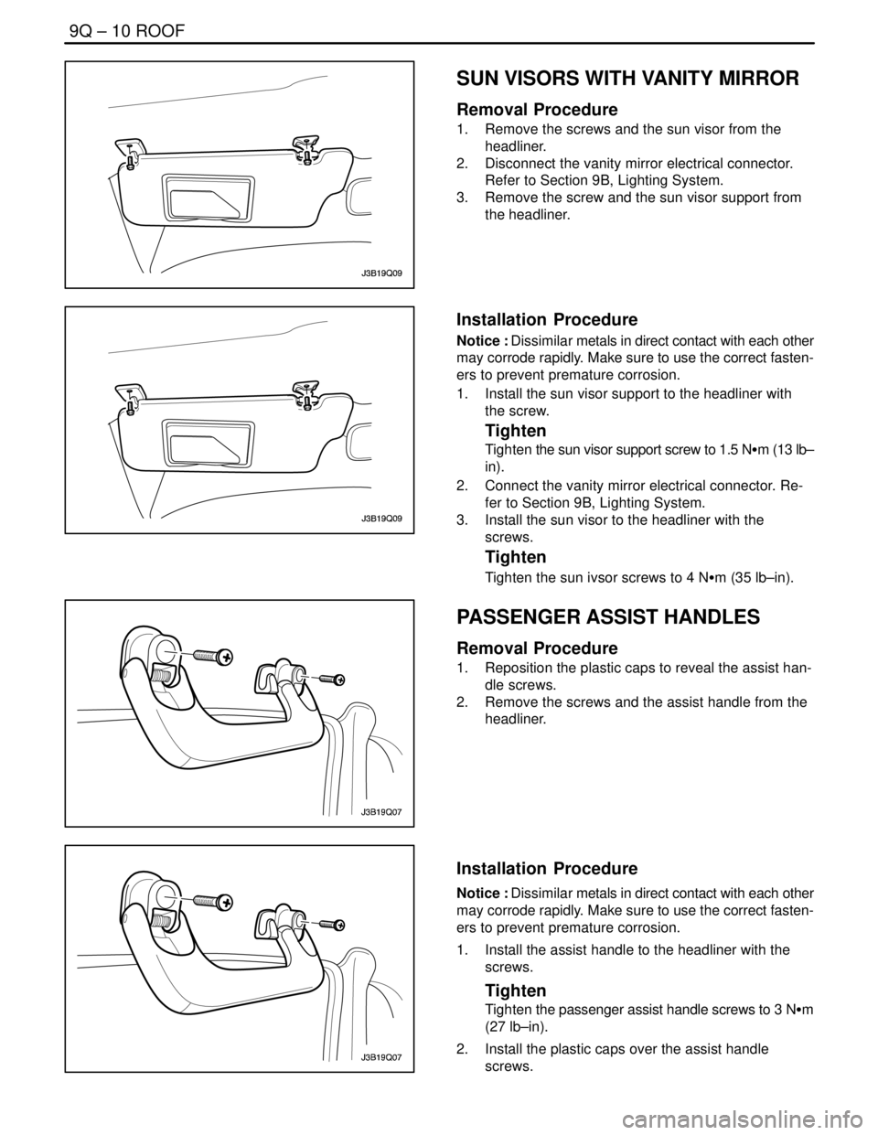
1. Reposition the plastic caps to reveal the assist han-
dle screws.
2. Remove the screws and the assist handle from the
headliner.
Installation Procedure
Notice : Dissimilar metals in direct contact with each other
may corrode rapidly. Make sure to use the correct fasten-
ers to prevent premature corrosion.
1. Install the assist handle to the headliner with the
screws.
Tighten
Tighten the passenger assist handle screws to 3 NSm
(27 lb–in).
2. Install the plastic caps over the assist handle
screws.
Page 2461 of 2643

9Q – 12IROOF
DAEWOO V–121 BL4
GENERAL DESCRIPTION
AND SYSTEM OPERATION
ROOF
The roof is a one–piece painted metal unit which incorpo-
rates a single solid headliner. There are two moldings, one
per side on the vehicle’s roof, which enclose and hide the
roof rail seams. The roof moldings are serviceable as indi-
vidual units.
The one–piece formed headliner consists of a molded
substrate covered with a foam–backed cloth facing. The
one–piece construction requires that the headliner be ser-
viced as a complete assembly.
POWER SUNROOF/SUNROOF
CONTROL SWITCH
The sunroof has the following characteristics:
S Intended to provide light and air through the roof
the vehicle.
S Built into the roof.
S Made of glass.
S Equipped with a sunshade that opens and closes
manually.
S Powered by an electric motor.
S Controlled by a toggle switch built into the interior
courtesy lamp assembly.
The sunroof control switch is a toggle button located on the
right side of the interior courtesy lamp assembly.
To operate the sunroof, the ignition must be ON.Tilting the Sunroof, Open and Closed
To tilt open the rear end of the sunroof, press and hold the
forward portion of the toggle button until the sunroof tilts
open.
To close the sunroof from a tilted–open position, press and
hold the rear portion of the toggle button until the sunroof
tilts closed.
Sliding the Sunroof, Open and Closed
To slide open the sunroof, press the rear portion of the
toggle button until the sunroof slides. If the sun shade is
closed, the sunroof will pull the sunshade open when the
sunroof slides open.
To close the sunroof from a slid–open position, press the
forward portion of the toggle button until the sunroof slides
closed.
SUN VISORS WITH VANITY MIRROR
The sun visors swing down in order to block out glare.
They also swing to the side when they are released from
the support. To replace the vanity mirror lamp, refer to
Section 9B, Lighting Systems.
PASSENGER ASSIST HANDLES
There is a passenger assist handle for each rear outboard
seat and for the front passenger seat. Passengers can use
these handles to assist in keeping their balance over rough
roads or during sharp turns.
COAT HOOKS
The coat hooks are located on the left and the right rear
passenger assist handles.