Page 2397 of 2643

9L – 18IGLASS AND MIRRORS
DAEWOO V–121 BL4
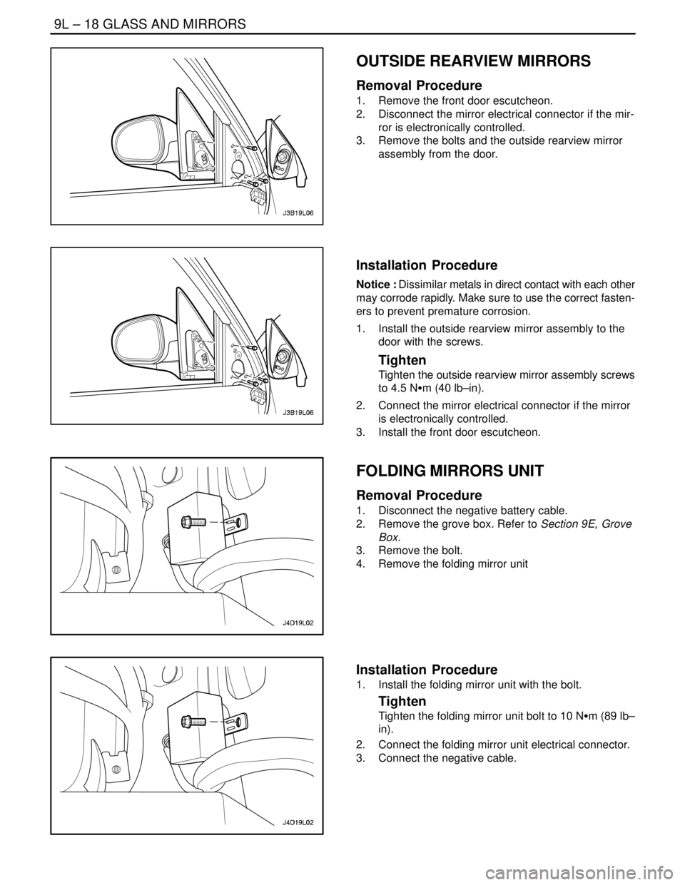
OUTSIDE REARVIEW MIRRORS
Removal Procedure
1. Remove the front door escutcheon.
2. Disconnect the mirror electrical connector if the mir-
ror is electronically controlled.
3. Remove the bolts and the outside rearview mirror
assembly from the door.
Installation Procedure
Notice : Dissimilar metals in direct contact with each other
may corrode rapidly. Make sure to use the correct fasten-
ers to prevent premature corrosion.
1. Install the outside rearview mirror assembly to the
door with the screws.
Tighten
Tighten the outside rearview mirror assembly screws
to 4.5 NSm (40 lb–in).
2. Connect the mirror electrical connector if the mirror
is electronically controlled.
3. Install the front door escutcheon.
FOLDING MIRRORS UNIT
Removal Procedure
1. Disconnect the negative battery cable.
2. Remove the grove box. Refer to Section 9E, Grove
Box.
3. Remove the bolt.
4. Remove the folding mirror unit
Installation Procedure
1. Install the folding mirror unit with the bolt.
Tighten
Tighten the folding mirror unit bolt to 10 NSm (89 lb–
in).
2. Connect the folding mirror unit electrical connector.
3. Connect the negative cable.
Page 2398 of 2643
GLASS AND MIRRORS 9L – 19
DAEWOO V–121 BL4
GENERAL DESCRIPTION
AND SYSTEM OPERATION
STATIONARY GLASS
Stationary glass consists of all the glass on the vehicle
which is immovable within its frame, such as the wind-
shield glass, the back glass, and the inside rearview mir-
ror.
ELECTRIC CONTROL HEATED
OUTSIDE REARVIEW MIRROR
The electric control for the heated outside rearview mirroris on the driver’s side door. The mirror defogger is acti-
vated by the rear window defogger switch.
INSIDE REARVIEW MIRROR
The rearview mirror pivots at the ball–and–socket mirror
pivot and can be manually adjusted up/down and left/right.
FOLDING MIRROR UNIT
The folding mirror system is automatically folding the mir-
ror in parking state.
Page 2436 of 2643
9P – 16IDOORS
DAEWOO V–121 BL4
MAINTENANCE AND REPAIR
ON–VEHICLE SERVICE
OUTSIDE CHANNEL MOLDING
(Front Door Shown, Rear Door Similar)
Removal Procedure
1. Lower the window completely.
2. Remove the outside channel molding screw.
3. Lift the outside channel molding off the door.
Installation Procedure
1. Press the outside channel molding onto the door.
Notice : Dissimilar metals in direct contact with each other
may corrode rapidly. Make sure to use the correct fasten-
ers to prevent premature corrosion.
2. Install the outside channel molding screw.
Tighten
Tighten the outside channel molding screw to 1.3 NSm
(12 lb–in).
3. Raise the window.
FRONT DOOR GLASS RUN
Removal Procedure
1. Remove the outside rearview mirror. Refer to Sec-
tion 9L, Glass and Mirrors.
2. Remove the front door glass. Refer to Section 9L,
Glass and Mirrors.
3. Remove the glass run.
Page 2437 of 2643
DOORS 9P – 17
DAEWOO V–121 BL4
Installation Procedure
1. Install the glass run.
2. Install the front door glass. Refer to Section 9L,
Glass and Mirrors.
3. Install the outside rearview mirror. Refer to Section
9L, Glass and Mirrors.
DOOR WEATHERSTRIP
(Front Door Shown, Rear Door Similar)
Removal Procedure
1. Remove the door hold–open link–to–body bolt and
the door hold–open link.
2. Remove the door weatherstrip.
Installation Procedure
1. Install the door weatherstrip.
Page 2438 of 2643
9P – 18IDOORS
DAEWOO V–121 BL4
Notice : Dissimilar metals in direct contact with each other
may corrode rapidly. Make sure to use the correct fasten-
ers to prevent premature corrosion.
2. Install the door hold–open link to the body with the
bolt.
Tighten
Tighten the door hold–open link–to–body bolt to 25
NSm (18 lb–ft).
REAR DOOR GLASS RUN
Removal Procedure
1. Remove the rear door glass. Refer to Section 9L,
Glass and Mirrors.
2. Remove the rear door glass run.
Installation Procedure
1. Install the rear door glass run.
2. Install the rear door glass. Refer to Section 9L,
Glass and Mirrors.
FRONT DOOR SECONDARY
WEATHERSTRIP
Removal Procedure
1. Remove the outside rearview mirror. Refer to Sec-
tion 9L, Glass and Mirrors.
2. Remove the front door secondary weatherstrip.
Page 2439 of 2643
DOORS 9P – 19
DAEWOO V–121 BL4
Installation Procedure
1. Install the front door secondary weatherstrip.
2. Install the outside rearview mirror. Refer to Section
9L, Glass and Mirrors.
REAR DOOR SECONDARY
WEATHERSTRIP
Removal Procedure
1. Remove the interior garnish molding.
2. Remove the screws and the exterior garnish mold-
ing.
3. Remove the rear door secondary weatherstrip.
Installation Procedure
1. Install the rear door secondary weatherstrip.
Notice : Dissimilar metals in direct contact with each other
may corrode rapidly. Make sure to use the correct fasten-
ers to prevent premature corrosion.
2. Install the exterior garnish molding with the screws.
3. Install the interior garnish molding.
FRONT DOOR OPENING
WEATHERSTRIP
Removal Procedure
1. Remove the kick panel, the front rocker panel, and
the lower B–pillar trim panel. Refer to Section 9G,
Interior Trim.
2. Remove the front door opening weatherstrip.
Page 2446 of 2643

9P – 26IDOORS
DAEWOO V–121 BL4
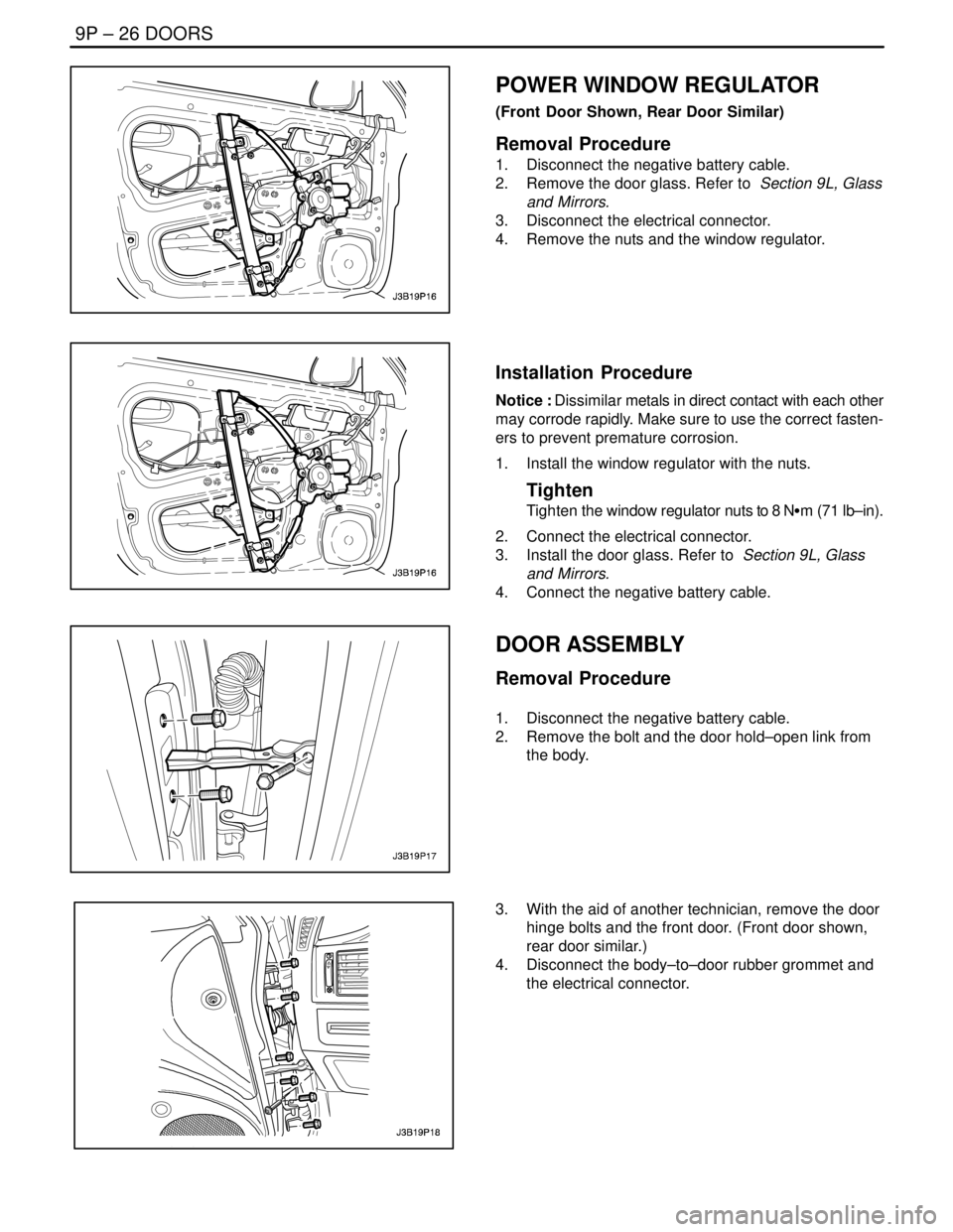
POWER WINDOW REGULATOR
(Front Door Shown, Rear Door Similar)
Removal Procedure
1. Disconnect the negative battery cable.
2. Remove the door glass. Refer to Section 9L, Glass
and Mirrors.
3. Disconnect the electrical connector.
4. Remove the nuts and the window regulator.
Installation Procedure
Notice : Dissimilar metals in direct contact with each other
may corrode rapidly. Make sure to use the correct fasten-
ers to prevent premature corrosion.
1. Install the window regulator with the nuts.
Tighten
Tighten the window regulator nuts to 8 NSm (71 lb–in).
2. Connect the electrical connector.
3. Install the door glass. Refer to Section 9L, Glass
and Mirrors.
4. Connect the negative battery cable.
DOOR ASSEMBLY
Removal Procedure
1. Disconnect the negative battery cable.
2. Remove the bolt and the door hold–open link from
the body.
3. With the aid of another technician, remove the door
hinge bolts and the front door. (Front door shown,
rear door similar.)
4. Disconnect the body–to–door rubber grommet and
the electrical connector.
Page 2450 of 2643

SECTION : 9Q
ROOF
CAUTION : Disconnect the negative battery cable before removing or installing any electrical unit or when a tool
or equipment could easily come in contact with exposed electrical terminals. Disconnecting this cable will help
prevent personal injury and damage to the vehicle. The ignition must also be in LOCK unless otherwise noted.
TABLE OF CONTENTS
SPECIFICATIONS9Q–2 . . . . . . . . . . . . . . . . . . . . . . . . . .
Fastener Tightening Specifications 9Q–2. . . . . . . . . . .
SPECIAL TOOLS9Q–2 . . . . . . . . . . . . . . . . . . . . . . . . . . .
Special Tools Table 9Q–2. . . . . . . . . . . . . . . . . . . . . . . .
SCHEMATIC AND ROUTING DIAGRAMS9Q–3 . . . . .
Power Sunroof System 9Q–3. . . . . . . . . . . . . . . . . . . . .
DIAGNOSIS9Q–4 . . . . . . . . . . . . . . . . . . . . . . . . . . . . . . . .
Power Sunroof 9Q–4. . . . . . . . . . . . . . . . . . . . . . . . . . . .
MAINTENANCE AND REPAIR9Q–6 . . . . . . . . . . . . . . .
ON–VEHICLE SERVICE 9Q–6. . . . . . . . . . . . . . . . . . . . .
Power Sunroof 9Q–6. . . . . . . . . . . . . . . . . . . . . . . . . . . .
Sun Shade 9Q–7. . . . . . . . . . . . . . . . . . . . . . . . . . . . . . . . Sunroof Glass 9Q–8. . . . . . . . . . . . . . . . . . . . . . . . . . . . .
Formed Headliner 9Q–8. . . . . . . . . . . . . . . . . . . . . . . . .
Sun Visors with Vanity Mirror 9Q–10. . . . . . . . . . . . . . .
Passenger Assist Handles 9Q–10. . . . . . . . . . . . . . . . .
Power Sunroof Control Switch 9Q–11. . . . . . . . . . . . . .
GENERAL DESCRIPTION AND SYSTEM
OPERATION9Q–12 . . . . . . . . . . . . . . . . . . . . . . . . . . . . .
Roof 9Q–12. . . . . . . . . . . . . . . . . . . . . . . . . . . . . . . . . . . .
Power Sunroof/Sunroof Control Switch 9Q–12. . . . . .
Sun Visors with Vanity Mirror 9Q–12. . . . . . . . . . . . . . .
Passenger Assist Handles 9Q–12. . . . . . . . . . . . . . . . .
Coat Hooks 9Q–12. . . . . . . . . . . . . . . . . . . . . . . . . . . . . .