Page 1990 of 2643

7A – 16IHEATING AND VENTILATION SYSTEM
DAEWOO V–121 BL4
BLOWER NOISE
StepActionValue(s)YesNo
1Verify the customer’s complaint.
Are the customer’s concerns verified?–Go to Step 2System OK
21. Sit inside the vehicle.
2. Close the doors and the windows.
3. Turn the ignition ON.
4. Start the engine.
5. Set the temperature to full cold.
6. Cycle through the blower speeds, the modes,
and the temperature settings in order to find
the noise.
Is the blower noise constant at high blower speeds
or certain modes, but absent at lower speeds or in
other modes?–Go to Step 11Go to Step 3
3Check for vibrations from the blower motor and fan
assembly at each blower speed by feeling the blower
motor housing.
Did you find excessive vibration?–Go to Step 6Go to Step 4
41. Remove the blower motor and the fan assem-
bly. Refer to ”Blower Motor” in this section.
2. Check for foreign material at the opening of the
blower inlet.
Do you find any foreign material at the blower inlet?–Go to Step 5Go to Step 6
5Remove all foreign material.
Is the repair complete?–System OKGo to Step 6
61. Examine the blower fan for wear spots,
cracked blades, a cracked hub, a loose fan re-
taining nut, or bad alignment.
2. Examine the blower case for wear spots.
Did you find any problem?–Go to Step 7Go to Step 9
7Repair as required.
Is the repair complete?–System OKGo to Step 8
8Replace the motor and the fan assembly.
Is the repair complete?–System OKGo to Step 9
9If the noise is a click/tick or whine, replace the motor.
Is the repair complete?–System OKGo to Step 10
10Reinstall the original motor.
Is the problem still present?–Go to Step 11System OK
111. Set the blower speed on maximum.
2. Check full–hot to full–cold temperature posi-
tions in the defrost, floor, and vent modes.
Is the noise present in the defrost mode only?–Go to Step 12Go to Step 13
121. Check the ducts for obstructions or foreign ma-
terials.
2. Remove any obstructions or foreign materials.
3. Check the floor/defroster door seals.
4. Repair or replace the components, as needed.
Is the repair complete?–System OK–
13Is the noise present in the floor mode only?–Go to Step 12Go to Step 14
14Is the noise present in the vent mode only?–Go to Step 15Go to Step 16
Page 1991 of 2643
HEATING AND VENTILATION SYSTEM 7A – 17
DAEWOO V–121 BL4
StepNo Yes Value(s) Action
151. Check the ducts for obstructions or foreign ma-
terials.
2. Remove any obstructions or foreign materials.
3. Check the vent door seals.
4. Repair or replace as needed.
Is the repair complete?–System OK–
16Is the noise present in all modes, but not all tempera-
ture positions?–Go to Step 17Go to Step 18
171. Check the temperature door seals.
2. Repair or replace the seals, as needed.
Is the repair complete?–System OK–
181. Check the system for obstructions or foreign
materials between the fan and the temperature
door.
2. Repair or replace the components, as needed.
Is the repair complete?–System OKGo to Step 2
Page 1992 of 2643
7A – 18IHEATING AND VENTILATION SYSTEM
DAEWOO V–121 BL4
MAINTENANCE AND REPAIR
ON–VEHICLE SERVICE
TEMPERATURE CABLE
ADJUSTMENT
Because the cable and the cable housings have fixed
lengths, it is impossible to make a temperature cable ad-
justment.
In addition, the heater/air distributor case linkage cannot
be adjusted.
If a malfunction is suspected, verify the proper operation
of the controller and the mechanical doors for the heater/
air distributor case assembly.
TEMPERATURE CONTROL CABLE
(Left–Hand Drive Shown, Right–Hand Drive
Similar)
Removal Procedure
1. Disconnect the negative battery cable.
2. Remove the center molding. Refer toSection 9E,
Instrumentation/Driver Information.
3. Disconnect the mode control cable from the mode
door.
4. Disconnect the temperature control cable eyelet
from the post on the controller.
5. Pry off the clip of the temperature control cable.
Page 1993 of 2643
HEATING AND VENTILATION SYSTEM 7A – 19
DAEWOO V–121 BL4
6. Slide the cable eyelet off the post on the tempera-
ture door lever.
7. Pry off the Clip of the temperature cable.
Installation Procedure
1. Install the temperature control cable eyelet to the
post on the temperature door lever.
2. Install the clip of the temperature cable.
3. Install the temperature control cable eyelet to the
post on the controller.
4. Install the clip of the temperature control cable.
5. Install the mode control cable to the mode door.
6. Insert the center molding into position on the instru-
ment panel.
7. Move the temperature control to verify the smooth
operation and function of the door and the cable.
8. Connect the negative battery cable.
9. Operate the heating and cooling systems to verify
proper function.
Page 1994 of 2643

7A – 20IHEATING AND VENTILATION SYSTEM
DAEWOO V–121 BL4
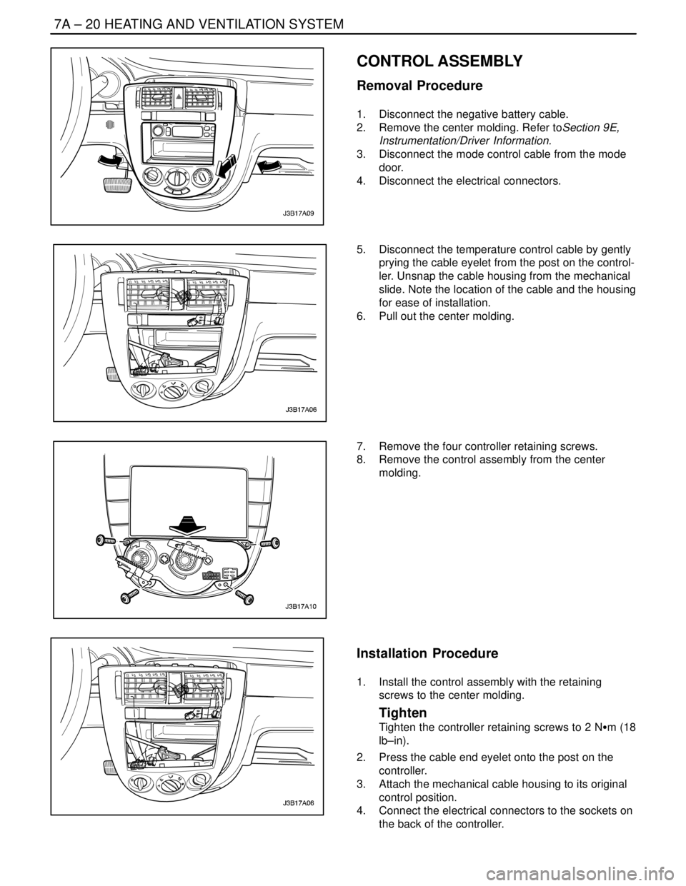
CONTROL ASSEMBLY
Removal Procedure
1. Disconnect the negative battery cable.
2. Remove the center molding. Refer toSection 9E,
Instrumentation/Driver Information.
3. Disconnect the mode control cable from the mode
door.
4. Disconnect the electrical connectors.
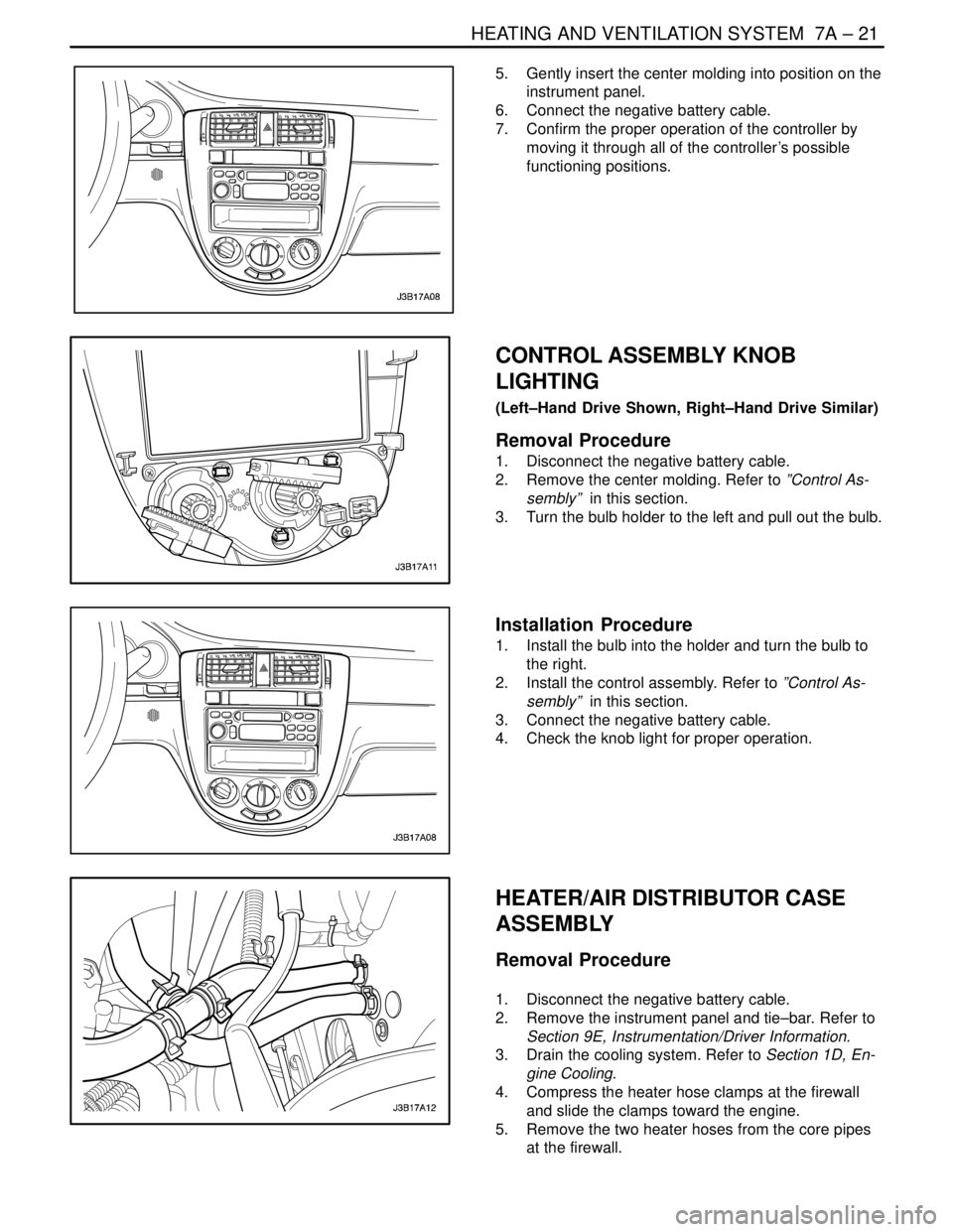
5. Disconnect the temperature control cable by gently
prying the cable eyelet from the post on the control-
ler. Unsnap the cable housing from the mechanical
slide. Note the location of the cable and the housing
for ease of installation.
6. Pull out the center molding.
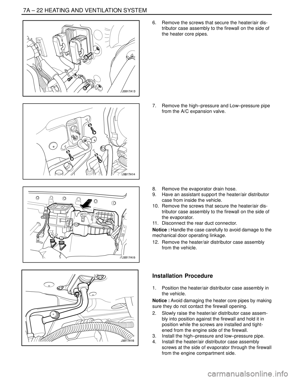
7. Remove the four controller retaining screws.
8. Remove the control assembly from the center
molding.
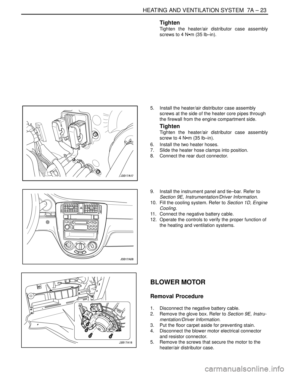
Installation Procedure
1. Install the control assembly with the retaining
screws to the center molding.
Tighten
Tighten the controller retaining screws to 2 NSm (18
lb–in).
2. Press the cable end eyelet onto the post on the
controller.
3. Attach the mechanical cable housing to its original
control position.
4. Connect the electrical connectors to the sockets on
the back of the controller.
Page 1995 of 2643

HEATING AND VENTILATION SYSTEM 7A – 21
DAEWOO V–121 BL4
5. Gently insert the center molding into position on the
instrument panel.
6. Connect the negative battery cable.
7. Confirm the proper operation of the controller by
moving it through all of the controller’s possible
functioning positions.
CONTROL ASSEMBLY KNOB
LIGHTING
(Left–Hand Drive Shown, Right–Hand Drive Similar)
Removal Procedure
1. Disconnect the negative battery cable.
2. Remove the center molding. Refer to ”Control As-
sembly” in this section.
3. Turn the bulb holder to the left and pull out the bulb.
Installation Procedure
1. Install the bulb into the holder and turn the bulb to
the right.
2. Install the control assembly. Refer to ”Control As-
sembly” in this section.
3. Connect the negative battery cable.
4. Check the knob light for proper operation.
HEATER/AIR DISTRIBUTOR CASE
ASSEMBLY
Removal Procedure
1. Disconnect the negative battery cable.
2. Remove the instrument panel and tie–bar. Refer to
Section 9E, Instrumentation/Driver Information.
3. Drain the cooling system. Refer to Section 1D, En-
gine Cooling.
4. Compress the heater hose clamps at the firewall
and slide the clamps toward the engine.
5. Remove the two heater hoses from the core pipes
at the firewall.
Page 1996 of 2643

7A – 22IHEATING AND VENTILATION SYSTEM
DAEWOO V–121 BL4
6. Remove the screws that secure the heater/air dis-
tributor case assembly to the firewall on the side of
the heater core pipes.
7. Remove the high–pressure and Low–pressure pipe
from the A/C expansion valve.
8. Remove the evaporator drain hose.
9. Have an assistant support the heater/air distributor
case from inside the vehicle.
10. Remove the screws that secure the heater/air dis-
tributor case assembly to the firewall on the side of
the evaporator.
11. Disconnect the rear duct connector.
Notice : Handle the case carefully to avoid damage to the
mechanical door operating linkage.
12. Remove the heater/air distributor case assembly
from the vehicle.
Installation Procedure
1. Position the heater/air distributor case assembly in
the vehicle.
Notice : Avoid damaging the heater core pipes by making
sure they do not contact the firewall opening.
2. Slowly raise the heater/air distributor case assem-
bly into position against the firewall and hold it in
position while the screws are installed and tight-
ened from the engine side of the firewall.
3. Install the high–pressure and low–pressure pipe.
4. Install the heater/air distributor case assembly
screws at the side of evaporator through the firewall
from the engine compartment side.
Page 1997 of 2643

HEATING AND VENTILATION SYSTEM 7A – 23
DAEWOO V–121 BL4
Tighten
Tighten the heater/air distributor case assembly
screws to 4 NSm (35 lb–in).
5. Install the heater/air distributor case assembly
screws at the side of the heater core pipes through
the firewall from the engine compartment side.
Tighten
Tighten the heater/air distributor case assembly
screw to 4 NSm (35 lb–in).
6. Install the two heater hoses.
7. Slide the heater hose clamps into position.
8. Connect the rear duct connector.
9. Install the instrument panel and tie–bar. Refer to
Section 9E, Instrumentation/Driver Information.
10. Fill the cooling system. Refer to Section 1D, Engine
Cooling.
11. Connect the negative battery cable.
12. Operate the controls to verify the proper function of
the heating and ventilation systems.
BLOWER MOTOR
Removal Procedure
1. Disconnect the negative battery cable.
2. Remove the glove box. Refer to Section 9E, Instru-
mentation/Driver Information.
3. Put the floor carpet aside for preventing stain.
4. Disconnect the blower motor electrical connector
and resistor connector.
5. Remove the screws that secure the motor to the
heater/air distributor case.