2004 DAEWOO NUBIRA heating
[x] Cancel search: heatingPage 1998 of 2643
7A – 24IHEATING AND VENTILATION SYSTEM
DAEWOO V–121 BL4
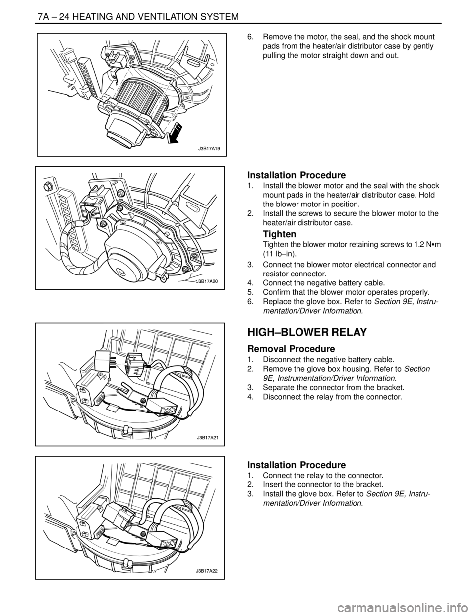
6. Remove the motor, the seal, and the shock mount
pads from the heater/air distributor case by gently
pulling the motor straight down and out.
Installation Procedure
1. Install the blower motor and the seal with the shock
mount pads in the heater/air distributor case. Hold
the blower motor in position.
2. Install the screws to secure the blower motor to the
heater/air distributor case.
Tighten
Tighten the blower motor retaining screws to 1.2 NSm
(11 lb–in).
3. Connect the blower motor electrical connector and
resistor connector.
4. Connect the negative battery cable.
5. Confirm that the blower motor operates properly.
6. Replace the glove box. Refer to Section 9E, Instru-
mentation/Driver Information.
HIGH–BLOWER RELAY
Removal Procedure
1. Disconnect the negative battery cable.
2. Remove the glove box housing. Refer to Section
9E, Instrumentation/Driver Information.
3. Separate the connector from the bracket.
4. Disconnect the relay from the connector.
Installation Procedure
1. Connect the relay to the connector.
2. Insert the connector to the bracket.
3. Install the glove box. Refer to Section 9E, Instru-
mentation/Driver Information.
Page 1999 of 2643
HEATING AND VENTILATION SYSTEM 7A – 25
DAEWOO V–121 BL4
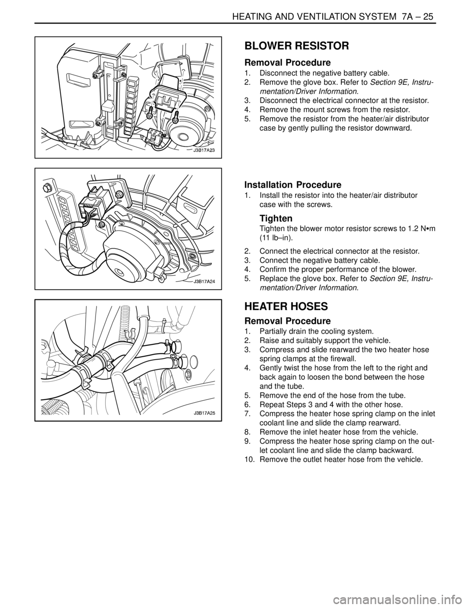
BLOWER RESISTOR
Removal Procedure
1. Disconnect the negative battery cable.
2. Remove the glove box. Refer to Section 9E, Instru-
mentation/Driver Information.
3. Disconnect the electrical connector at the resistor.
4. Remove the mount screws from the resistor.
5. Remove the resistor from the heater/air distributor
case by gently pulling the resistor downward.
Installation Procedure
1. Install the resistor into the heater/air distributor
case with the screws.
Tighten
Tighten the blower motor resistor screws to 1.2 NSm
(11 lb–in).
2. Connect the electrical connector at the resistor.
3. Connect the negative battery cable.
4. Confirm the proper performance of the blower.
5. Replace the glove box. Refer to Section 9E, Instru-
mentation/Driver Information.
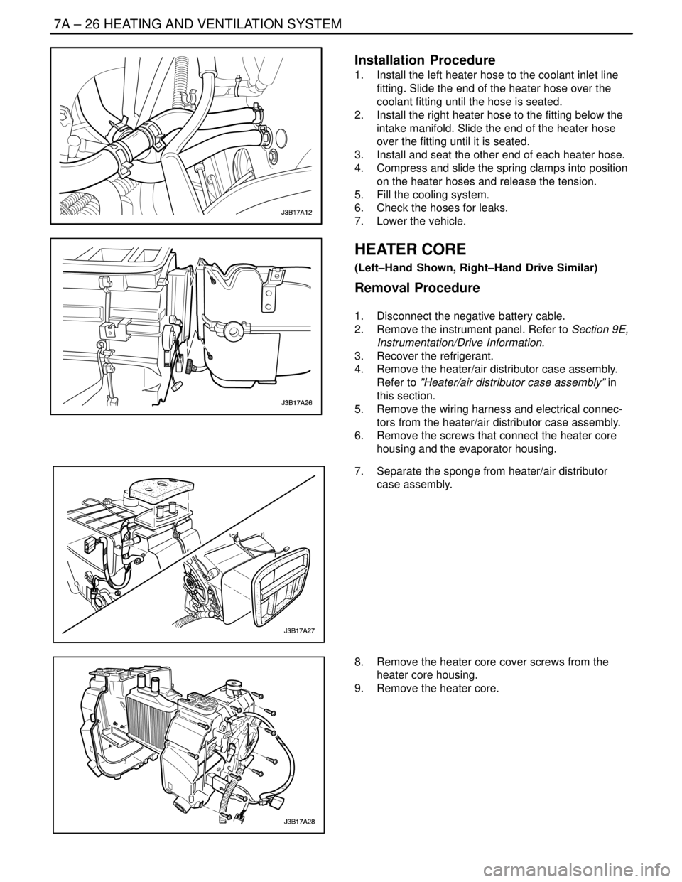
HEATER HOSES
Removal Procedure
1. Partially drain the cooling system.
2. Raise and suitably support the vehicle.
3. Compress and slide rearward the two heater hose
spring clamps at the firewall.
4. Gently twist the hose from the left to the right and
back again to loosen the bond between the hose
and the tube.
5. Remove the end of the hose from the tube.
6. Repeat Steps 3 and 4 with the other hose.
7. Compress the heater hose spring clamp on the inlet
coolant line and slide the clamp rearward.
8. Remove the inlet heater hose from the vehicle.
9. Compress the heater hose spring clamp on the out-
let coolant line and slide the clamp backward.
10. Remove the outlet heater hose from the vehicle.
Page 2000 of 2643
7A – 26IHEATING AND VENTILATION SYSTEM
DAEWOO V–121 BL4
Installation Procedure
1. Install the left heater hose to the coolant inlet line
fitting. Slide the end of the heater hose over the
coolant fitting until the hose is seated.
2. Install the right heater hose to the fitting below the
intake manifold. Slide the end of the heater hose
over the fitting until it is seated.
3. Install and seat the other end of each heater hose.
4. Compress and slide the spring clamps into position
on the heater hoses and release the tension.
5. Fill the cooling system.
6. Check the hoses for leaks.
7. Lower the vehicle.
HEATER CORE
(Left–Hand Shown, Right–Hand Drive Similar)
Removal Procedure
1. Disconnect the negative battery cable.
2. Remove the instrument panel. Refer to Section 9E,
Instrumentation/Drive Information.
3. Recover the refrigerant.
4. Remove the heater/air distributor case assembly.
Refer to ”Heater/air distributor case assembly” in
this section.
5. Remove the wiring harness and electrical connec-
tors from the heater/air distributor case assembly.
6. Remove the screws that connect the heater core
housing and the evaporator housing.
7. Separate the sponge from heater/air distributor
case assembly.
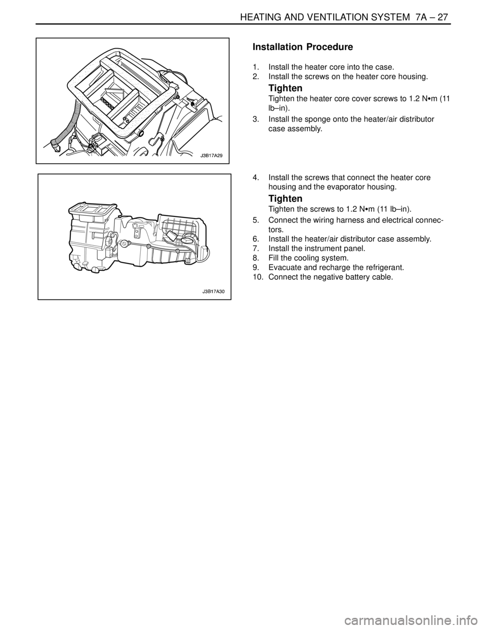
8. Remove the heater core cover screws from the
heater core housing.
9. Remove the heater core.
Page 2001 of 2643
HEATING AND VENTILATION SYSTEM 7A – 27
DAEWOO V–121 BL4
Installation Procedure
1. Install the heater core into the case.
2. Install the screws on the heater core housing.
Tighten
Tighten the heater core cover screws to 1.2 NSm (11
lb–in).
3. Install the sponge onto the heater/air distributor
case assembly.
4. Install the screws that connect the heater core
housing and the evaporator housing.
Tighten
Tighten the screws to 1.2 NSm (11 lb–in).
5. Connect the wiring harness and electrical connec-
tors.
6. Install the heater/air distributor case assembly.
7. Install the instrument panel.
8. Fill the cooling system.
9. Evacuate and recharge the refrigerant.
10. Connect the negative battery cable.
Page 2002 of 2643

7A – 28IHEATING AND VENTILATION SYSTEM
DAEWOO V–121 BL4
GENERAL DESCRIPTION
AND SYSTEM OPERATION
HEATING AND VENTILATION
SYSTEMS
The base heater system is designed to provide heating,
ventilation, windshield defrosting, side window defogging,
and on some vehicles, heating directly to the rear seat
area.
The heater and fan assembly blower regulates the airflow
from the air inlet for further processing and distribution.
The heater core transfers the heat from the engine coolant
to the inlet air.
The temperature door regulates the amount of the air that
passes through the heater core. The temperature door
also controls the temperature of the air by controlling the
mix of the heated air and the ambient air.
The mode door regulates the flow and the distribution of
the processed air to the heater ducts and to the defroster
ducts.
This console–mounted heating and ventilation panel con-
tains the following:
The Rotary Temperature Control Knob
1. The Rotary Temperature Control Knob
S Actuates by cable.
S Raises the temperature of the air entering the
vehicle by rotation toward the right, or the red
portion of the knob.
2. The Rotary Blower Control Knob
S Turns ON to operate the blower motor at four
speeds.
S Turns OFF to stop the blower.
S Operates completely independently both from
the mode control that regulates the defroster
door and from the temperature control knob.S Changes the fan speed in any mode and at any
temperature setting.
3. The Rotary Mode Control Knob
S Actuates by cable.
S Regulates the air distribution between the wind-
shield, the instrument panel, and the floor vents.
Two Push Knobs
1. The Rear Window Defogger Push Knob
S Controls the rear window defogger.
S Turns ON the rear window defogger when the
push knob is pressed and the indicator lamp is
illuminated.
2. The A/C Push Knob (if the vehicle is equipped with
air conditioning)
S Controls the A/C.
S Turns the A/C ON when the push knob is down.
However, if the blower control knob is OFF, the
A/C system is OFF, regardless of the position of
the A/C knob.
Fresh Air Control Level Or Push Knob
1. The Fresh Air Control Level
S Operates by cable.
S Switches between recirculating passenger
compartment air and bringing outside air into the
passenger compartment.
S Draws in outside air when the lever is moved to
the right.
S Recirculates inside air when the lever is moved
to the left.
2. The Fresh Air Control Push Knob
S Operates by cable.
S Switches between recirculating passenger
compartment air and bringing outside air into the
passenger compartment.
S Draws in outside air when knob is off.
S Recirculates inside air when the knob is down
with the indicator lamp illuminated.
Page 2003 of 2643

SECTION : 7B
MANUAL CONTROL HEATING, VENTILATION
AND AIR CONDITIONING SYSTEM
CAUTION : Disconnect the negative battery cable before removing or installing any electrical unit or when a tool
or equipment could easily come in contact with exposed electrical terminals. Disconnecting this cable will help
prevent personal injury and damage to the vehicle. The ignition must also be in LOCK unless otherwise noted.
TABLE OF CONTENTS
SPECIFICATIONS7B–2 . . . . . . . . . . . . . . . . . . . . . . . . . .
General Specifications 7B–2. . . . . . . . . . . . . . . . . . . . .
Fastener Tightening Specifications 7B–2. . . . . . . . . . .
SPECIAL TOOLS7B–3 . . . . . . . . . . . . . . . . . . . . . . . . . . .
Special Tools Table 7B–3. . . . . . . . . . . . . . . . . . . . . . . .
SCHEMATIC AND ROUTING DIAGRAMS7B–6 . . . . .
A/C System – Typical 7B–6. . . . . . . . . . . . . . . . . . . . . .
Manual Control A/C Diagram 7B–7. . . . . . . . . . . . . . . .
DIAGNOSIS7B–8 . . . . . . . . . . . . . . . . . . . . . . . . . . . . . . . .
GENERAL DIAGNOSIS 7B–8. . . . . . . . . . . . . . . . . . . . . .
Testing the Refrigerant System 7B–8. . . . . . . . . . . . . .
Insufficient Cooling ”Quick Check” Procedure 7B–8. .
A/C Performance Test 7B–9. . . . . . . . . . . . . . . . . . . . . .
Pressure–Temperature Relationship of
R–134A 7B–10. . . . . . . . . . . . . . . . . . . . . . . . . . . . . . .
Leak Testing Refrigerant System 7B–11. . . . . . . . . . . .
V5 SYSTEM AIR CONDITIONING DIAGNOSIS 7B–12
Insufficient Cooling Diagnosis 7B–12. . . . . . . . . . . . . .
SYMPTOM DIAGNOSIS 7B–16. . . . . . . . . . . . . . . . . . . .
Pressure Test Chart (R–134A System) 7B–16. . . . . .
Low and High Side Pressure Relationship
Chart 7B–18. . . . . . . . . . . . . . . . . . . . . . . . . . . . . . . . . .
MAINTENANCE AND REPAIR7B–19 . . . . . . . . . . . . . .
ON–VEHICLE SERVICE 7B–19. . . . . . . . . . . . . . . . . . . .
GENERAL A/C SYSTEM SERVICE
PROCEDURES 7B–19. . . . . . . . . . . . . . . . . . . . . . . . . .
O–Ring Replacement 7B–19. . . . . . . . . . . . . . . . . . . . .
Handling Refrigerant 7B–19. . . . . . . . . . . . . . . . . . . . . .
Handling of Refrigerant Lines and Fittings 7B–19. . . .
Maintaining Chemical Stability in the Refrigeration
System 7B–20. . . . . . . . . . . . . . . . . . . . . . . . . . . . . . . .
Discharging, Adding Oil, Evacuating, and Charging
Procedures for A/C System 7B–20. . . . . . . . . . . . . .
SERVICEABLE COMPONENTS 7B–23. . . . . . . . . . . . . Components Used In Non–A/C Systems 7B–23. . . . .
A/C Pressure Transducer 7B–24. . . . . . . . . . . . . . . . . .
A/C Compressor Relay 7B–24. . . . . . . . . . . . . . . . . . . .
Air Filter 7B–25. . . . . . . . . . . . . . . . . . . . . . . . . . . . . . . . .
A/C Expansion Valve 7B–25. . . . . . . . . . . . . . . . . . . . . .
A/C High–Pressure Pipe Line 7B–26. . . . . . . . . . . . . . .
Evaporator Core 7B–29. . . . . . . . . . . . . . . . . . . . . . . . . .
A/C Suction Hose Assembly 7B–30. . . . . . . . . . . . . . .
A/C Discharge Hose Compressor to
Condenser 7B–31. . . . . . . . . . . . . . . . . . . . . . . . . . . . .
Receiver–Dryer 7B–32. . . . . . . . . . . . . . . . . . . . . . . . . . .
Compressor 7B–33. . . . . . . . . . . . . . . . . . . . . . . . . . . . . .
Condenser 7B–35. . . . . . . . . . . . . . . . . . . . . . . . . . . . . . .
UNIT REPAIR 7B–37. . . . . . . . . . . . . . . . . . . . . . . . . . . . .
COMPONENT LOCATOR 7B–37. . . . . . . . . . . . . . . . . . .
V5 Compressor 7B–37. . . . . . . . . . . . . . . . . . . . . . . . . . .
V5 AIR CONDITIONING COMPRESSOR
OVERHAUL 7B–38. . . . . . . . . . . . . . . . . . . . . . . . . . . . .
Clutch Plate and Hub Assembly 7B–38. . . . . . . . . . . .
Clutch Rotor and Bearing 7B–40. . . . . . . . . . . . . . . . . .
Clutch Coil 7B–42. . . . . . . . . . . . . . . . . . . . . . . . . . . . . . .
Shaft Seal Replacement 7B–44. . . . . . . . . . . . . . . . . . .
Control Valve Assembly 7B–46. . . . . . . . . . . . . . . . . . .
Rear Head, Gasket, Valve Plate, Reed Plate,
and O–ring 7B–47. . . . . . . . . . . . . . . . . . . . . . . . . . . . .
Cylinder to Front Head O–ring 7B–48. . . . . . . . . . . . . .
Leak Testing (External) 7B–50. . . . . . . . . . . . . . . . . . . .
GENERAL DESCRIPTION AND SYSTEM
OPERATION7B–51 . . . . . . . . . . . . . . . . . . . . . . . . . . . . .
GENERAL INFORMATION 7B–51. . . . . . . . . . . . . . . . . .
The V5 A/C System 7B–51. . . . . . . . . . . . . . . . . . . . . . .
System Components – Functional 7B–51. . . . . . . . . .
System Components – Control 7B–52. . . . . . . . . . . . .
V5 Compressor – General Description 7B–52. . . . . . .
V5 Compressor – Description of Operation 7B–52. . .
Page 2004 of 2643

7B – 2IMANUAL CONTROL HEATING, VENTILATION AND AIR CONDITIONING SYSTEM
DAEWOO V–121 BL4
SPECIFICATIONS
GENERAL SPECIFICATIONS
ApplicationUnitDescription
Compressor–V5
Receiver–Dryer–AL R/DRIER
RefrigerantType–R–134a System
Capacityg640±20 (RHD : 680±20)
Refrigerant Oil in A/C SystemType–Union Carbide 488 PAG OIL
Capacitycc (ml)220
Evaporator Capacity (Airflow rate 8.7 kg/min)Kcal/h6000±10%
FASTENER TIGHTENING SPECIFICATIONS
ApplicationNSmLb–FtLb–In
Pressure Transducer7–62
Expansion Valve Stud Bolts8–71
Liquid Pipe Support Clamp Bolts4–35
Liquid Pipe Block–to–Receiver Dryer Retaining Nut1410–
Liquid Pipe Block–to–Expansion Valve Retaining Nut1410–
Refrigerant Discharge Hose Block–to–Condenser Retaining Nut1612–
Refrigerant Discharge Hose Block–to–Compressor Retaining Nut3324–
Evaporator Core Cover Screws1.2–11
Heater Core Housing–to–Evaporator Housing Retaining Screws1.2–11
Suction Hose Block–to–Compressor Retaining Nut3324–
Suction Hose Support Clamp–to–Longitudinal Member Bolt8–71
Suction Hose Support Clamp–to–Engine Bracket Bolt (1.4D, 1.6D only)4–35
Suction Hose Support Clamp–to–Engine Bracket Bolt (1.8D, 2.0D only)1410–
Suction Hose Block–to–Expansion Valve Retaining Nut1410–
(Receiver Dryer) Band Clamp Bolt5–44
Receiver Dryer–to–Condenser Pipe Block Bolt5–44
Upper Compressor–to–Bracket Mounting Bolts (1.4D, 1.6D only)2518–
Lower Compressor–to–Bracket Mounting Bolts (1.4D, 1.6D only)4533–
Front Compressor–to–Bracket Mounting Bolts (1.8D, 2.0D only)3526–
Rear Compressor–to–Bracket Mounting Bolts (1.8D, 2.0D only)2015–
Condenser Mount Bolts4–35
(Compressor) Clutch Plate and Hub Assembly Retaining Nut1713–
(Compressor) Through Bolts10–89
Page 2005 of 2643
MANUAL CONTROL HEATING, VENTILATION AND AIR CONDITIONING SYSTEM 7B – 3
DAEWOO V–121 BL4
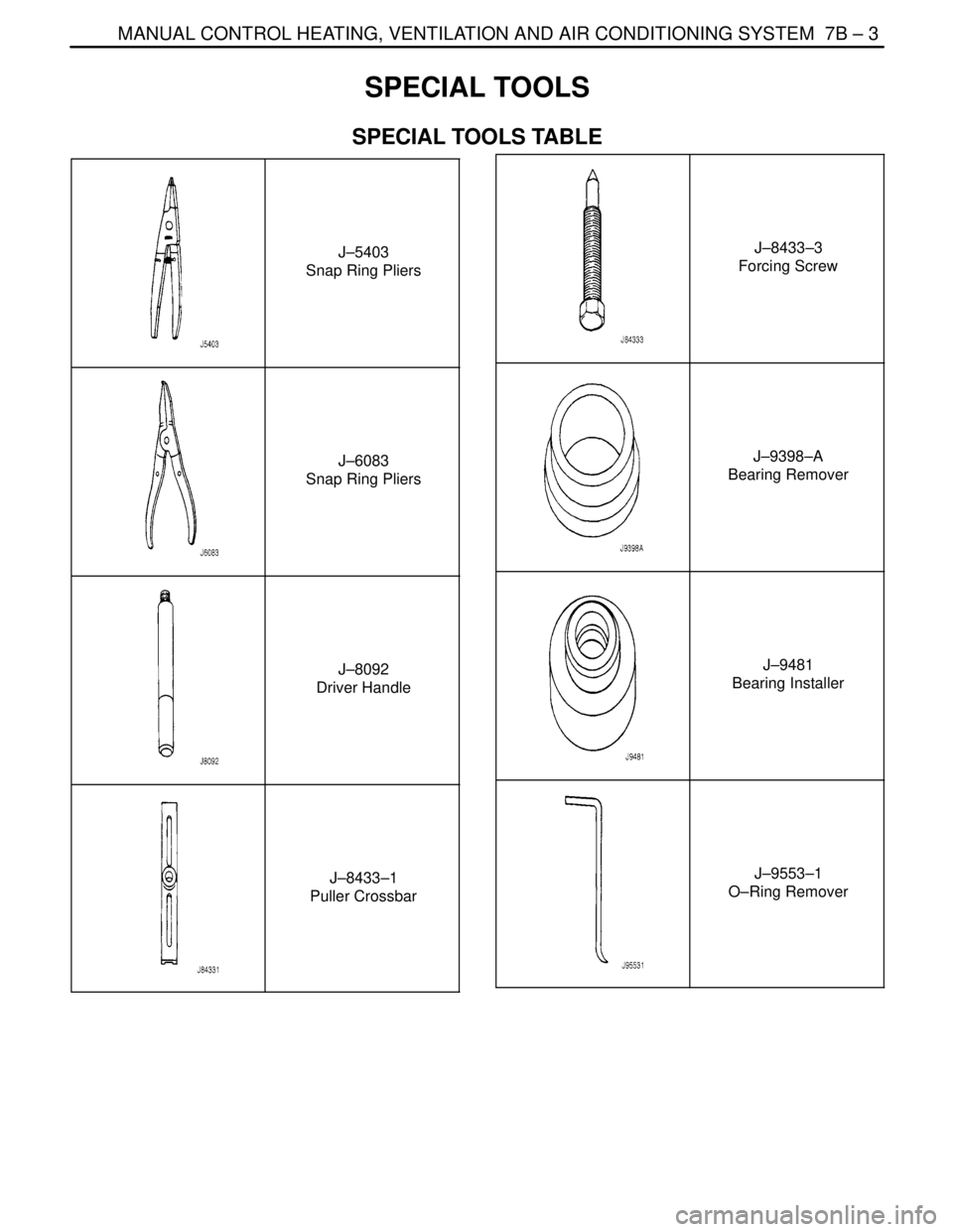
SPECIAL TOOLS
SPECIAL TOOLS TABLE
J–5403
Snap Ring Pliers
J–6083
Snap Ring Pliers
J–8092
Driver Handle
J–8433–1
Puller Crossbar
J–8433–3
Forcing Screw
J–9398–A
Bearing Remover
J–9481
Bearing Installer
J–9553–1
O–Ring Remover