2004 DAEWOO NUBIRA check engine
[x] Cancel search: check enginePage 178 of 2643
1C2 – 58I1.8L DOHC ENGINE MECHANICAL
DAEWOO V–121 BL4
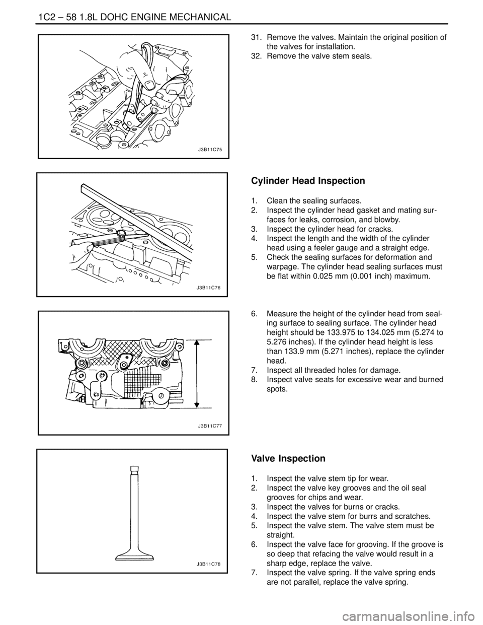
31. Remove the valves. Maintain the original position of
the valves for installation.
32. Remove the valve stem seals.
Cylinder Head Inspection
1. Clean the sealing surfaces.
2. Inspect the cylinder head gasket and mating sur-
faces for leaks, corrosion, and blowby.
3. Inspect the cylinder head for cracks.
4. Inspect the length and the width of the cylinder
head using a feeler gauge and a straight edge.
5. Check the sealing surfaces for deformation and
warpage. The cylinder head sealing surfaces must
be flat within 0.025 mm (0.001 inch) maximum.
6. Measure the height of the cylinder head from seal-
ing surface to sealing surface. The cylinder head
height should be 133.975 to 134.025 mm (5.274 to
5.276 inches). If the cylinder head height is less
than 133.9 mm (5.271 inches), replace the cylinder
head.
7. Inspect all threaded holes for damage.
8. Inspect valve seats for excessive wear and burned
spots.
Valve Inspection
1. Inspect the valve stem tip for wear.
2. Inspect the valve key grooves and the oil seal
grooves for chips and wear.
3. Inspect the valves for burns or cracks.
4. Inspect the valve stem for burrs and scratches.
5. Inspect the valve stem. The valve stem must be
straight.
6. Inspect the valve face for grooving. If the groove is
so deep that refacing the valve would result in a
sharp edge, replace the valve.
7. Inspect the valve spring. If the valve spring ends
are not parallel, replace the valve spring.
Page 179 of 2643
1.8L DOHC ENGINE MECHANICAL 1C2 – 59
DAEWOO V–121 BL4
8. Inspect the valve spring seating surface of the
valve rotators for wear or gouges. Replace as re-
quired.
Cleaning Procedure
1. Clean the cylinder head.
2. Clean the valve guides.
3. Clean all of the threaded holes.
4. Clean the valves of carbon, oil, and varnish.
Cylinder Head Overhaul
Valve Grind–in
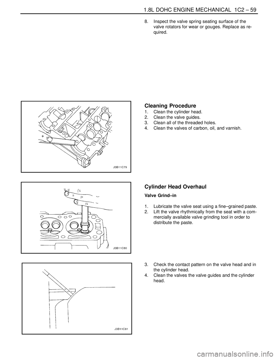
1. Lubricate the valve seat using a fine–grained paste.
2. Lift the valve rhythmically from the seat with a com-
mercially available valve grinding tool in order to
distribute the paste.
3. Check the contact pattern on the valve head and in
the cylinder head.
4. Clean the valves the valve guides and the cylinder
head.
Page 187 of 2643

1.8L DOHC ENGINE MECHANICAL 1C2 – 67
DAEWOO V–121 BL4
3. Install the crankshaft.
4. Install the lower crankshaft bearings in the bearing
caps.
5. Inspect the crankshaft end play with the crankshaft
bearings installed.
6. Check for permissible crankshaft end play. Refer to
”Engine Specifications” in this section.
7. With the crankshaft mounted on the front and rear
crankshaft bearings, check the middle crankshaft
journal for permissible out–of–round (runout). Refer
to ”Engine Specifications” in this section.
Important : Grease the crankshaft journals and lubricate
the crankshaft bearings slightly so that the plastic gauging
thread does not tear when the crankshaft bearing caps are
removed.
8. Inspect all of the crankshaft bearing clearances us-
ing a commercially available plastic gauging (ductile
plastic threads).
9. Cut the plastic gauging threads to the length of the
bearing width. Lay them axially between the crank-
shaft journals and the crankshaft bearings.
10. Install the crankshaft bearing caps and the bolts.
Tighten
Tighten the crankshaft bearing cap bolts to 50 NSm
(37 lb–ft) plus 45 degrees and 15 degrees.
11. Remove the crankshaft bearing cap bolts and the
caps.
12. Measure the width of the flattened plastic thread of
the plastic gauging using a ruler. (Plastic gauging is
available for different tolerance ranges.)
13. Inspect the bearing clearance for permissible toler-
ance ranges. Refer to ”Engine Specifications” in
this section.
Page 191 of 2643
1.8L DOHC ENGINE MECHANICAL 1C2 – 71
DAEWOO V–121 BL4
Notice : Take extreme care to prevent any scratches,
nicks or damage to the camshafts.
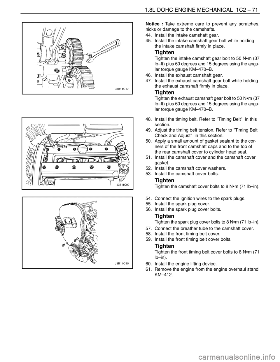
44. Install the intake camshaft gear.
45. Install the intake camshaft gear bolt while holding
the intake camshaft firmly in place.
Tighten
Tighten the intake camshaft gear bolt to 50 NSm (37
lb–ft) plus 60 degrees and 15 degrees using the angu-
lar torque gauge KM–470–B.
46. Install the exhaust camshaft gear.
47. Install the exhaust camshaft gear bolt while holding
the exhaust camshaft firmly in place.
Tighten
Tighten the exhaust camshaft gear bolt to 50 NSm (37
lb–ft) plus 60 degrees and 15 degrees using the angu-
lar torque gauge KM–470–B.
48. Install the timing belt. Refer to ”Timing Belt” in this
section.
49. Adjust the timing belt tension. Refer to ”Timing Belt
Check and Adjust” in this section.
50. Apply a small amount of gasket sealant to the cor-
ners of the front camshaft caps and to the top of
the rear camshaft cover to cylinder head seal.
51. Install the camshaft cover and the camshaft cover
gasket.
52. Install the camshaft cover washers.
53. Install the camshaft cover bolts.
Tighten
Tighten the camshaft cover bolts to 8 NSm (71 lb–in).
54. Connect the ignition wires to the spark plugs.
55. Install the spark plug cover.
56. Install the spark plug cover bolts.
Tighten
Tighten the spark plug cover bolts to 8 NSm (71 lb–in).
57. Connect the breather tube to the camshaft cover.
58. Install the front timing belt cover.
59. Install the front timing belt cover bolts.
Tighten
Tighten the front timing belt cover bolts to 8 NSm (71
lb–in).
60. Install the engine lifting device.
61. Remove the engine from the engine overhaul stand
KM–412.
Page 192 of 2643
1C2 – 72I1.8L DOHC ENGINE MECHANICAL
DAEWOO V–121 BL4
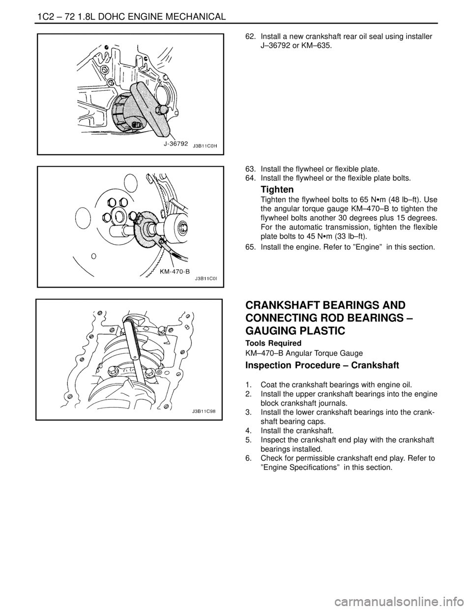
62. Install a new crankshaft rear oil seal using installer
J–36792 or KM–635.
63. Install the flywheel or flexible plate.
64. Install the flywheel or the flexible plate bolts.
Tighten
Tighten the flywheel bolts to 65 NSm (48 lb–ft). Use
the angular torque gauge KM–470–B to tighten the
flywheel bolts another 30 degrees plus 15 degrees.
For the automatic transmission, tighten the flexible
plate bolts to 45 NSm (33 lb–ft).
65. Install the engine. Refer to ”Engine” in this section.
CRANKSHAFT BEARINGS AND
CONNECTING ROD BEARINGS –
GAUGING PLASTIC
Tools Required
KM–470–B Angular Torque Gauge
Inspection Procedure – Crankshaft
1. Coat the crankshaft bearings with engine oil.
2. Install the upper crankshaft bearings into the engine
block crankshaft journals.
3. Install the lower crankshaft bearings into the crank-
shaft bearing caps.
4. Install the crankshaft.
5. Inspect the crankshaft end play with the crankshaft
bearings installed.
6. Check for permissible crankshaft end play. Refer to
”Engine Specifications” in this section.
Page 193 of 2643
1.8L DOHC ENGINE MECHANICAL 1C2 – 73
DAEWOO V–121 BL4
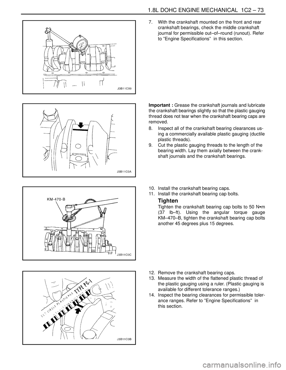
7. With the crankshaft mounted on the front and rear
crankshaft bearings, check the middle crankshaft
journal for permissible out–of–round (runout). Refer
to ”Engine Specifications” in this section.
Important : Grease the crankshaft journals and lubricate
the crankshaft bearings slightly so that the plastic gauging
thread does not tear when the crankshaft bearing caps are
removed.
8. Inspect all of the crankshaft bearing clearances us-
ing a commercially available plastic gauging (ductile
plastic threads).
9. Cut the plastic gauging threads to the length of the
bearing width. Lay them axially between the crank-
shaft journals and the crankshaft bearings.
10. Install the crankshaft bearing caps.
11. Install the crankshaft bearing cap bolts.
Tighten
Tighten the crankshaft bearing cap bolts to 50 NSm
(37 lb–ft). Using the angular torque gauge
KM–470–B, tighten the crankshaft bearing cap bolts
another 45 degrees plus 15 degrees.
12. Remove the crankshaft bearing caps.
13. Measure the width of the flattened plastic thread of
the plastic gauging using a ruler. (Plastic gauging is
available for different tolerance ranges.)
14. Inspect the bearing clearances for permissible toler-
ance ranges. Refer to ”Engine Specifications” in
this section.
Page 198 of 2643
ENGINE COOLING 1D – 3
DAEWOO V–121 BL4
DIAGNOSIS
THERMOSTAT TEST
1. Remove the thermostat from the vehicle. Refer to
”Thermostat” in this section.
2. Make sure the valve spring is tight when the ther-
mostat is fully closed. If the spring is not tight, re-
place the thermostat.
3. Suspend the thermostat and a thermometer in a
pan of 50/50 mixture of ethylene glycol and water.
Do not let the thermostat or the thermometer rest
on the bottom of the pan because the uneven con-
centration of heat on the bottom could result in in-
accurate temperature measurements.
4. Heat the pan on a burner.
5. Use the thermometer to measure the temperature
of the heated solution.
6. The thermostat should begin to open at 87°C
(189°F) and it should be fully open at 102°C
(216°F). If it does not open at these temperatures,
replace the thermostat.
SURGE TANK CAP TEST
Tools Required
KM–471 Adapter
The surge tank cap maintains proper pressure, protects
the system from high pressure by opening a pressure
valve, and protects the coolant hoses from collapsing be-
cause of a vacuum.1. Wash any sludge from the surge tank cap and the
valve seat of the vacuum pressure valve for the
surge tank cap.
2. Check for any damage or deformity to the vacuum
pressure valve for the surge tank cap. If any dam-
age or deformity is found, replace the cap.
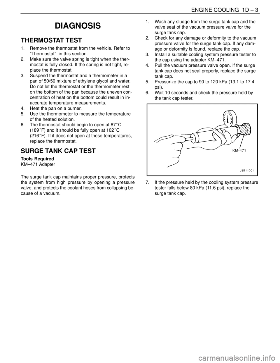
3. Install a suitable cooling system pressure tester to
the cap using the adapter KM–471.
4. Pull the vacuum pressure valve open. If the surge
tank cap does not seal properly, replace the surge
tank cap.
5. Pressurize the cap to 90 to 120 kPa (13.1 to 17.4
psi).
6. Wait 10 seconds and check the pressure held by
the tank cap tester.
7. If the pressure held by the cooling system pressure
tester falls below 80 kPa (11.6 psi), replace the
surge tank cap.
Page 199 of 2643

1D – 4IENGINE COOLING
DAEWOO V–121 BL4
COOLING SYSTEM DIAGNOSIS
Engine Overheats
ChecksAction
Check for a loss of the coolant.Add the coolant.
Check for a weak coolant solution.Confirm that the coolant solution is a 50/50 mixture of eth-
ylene glycol and water.
Check the front of the radiator for any dirt, any leaves, or
any insects.Clean the front of the radiator.
Check for leakage from the hoses, the coolant pump, the
heater, the thermostat housing, the radiator, the core
plugs, or the head gasket.Replace any damaged components.
Check for a faulty thermostat.Replace a damaged thermostat.
Check for retarded ignition timing.Perform an ECM code diagnosis. Confirm the integrity of
the timing belt.
Check for an improperly operating electric cooling fan.Replace the electric cooling fan.
Check for radiator hoses that are plugged or rotted.Replace any damaged radiator hoses.
Check for a faulty water pump.Replace a faulty water pump.
Check for a faulty surge tank cap.Replace a faulty surge tank cap.
Check for a cylinder head or an engine block that is
cracked or plugged.Repair the damaged cylinder head or the damaged engine
block.
Loss of Coolant
ChecksAction
Check for a leak in the radiator.Replace a damaged radiator.
Check for a leak in the following locations:
S Surge tank.
S Hose.Replace the following parts, as needed:
S Surge tank.
S Hose.
Check for loose or damaged radiator hoses, heater hoses,
and connections.Reseat the hoses.
Replace the hoses or the clamps.
Check for leaks in the coolant pump seal.Replace the coolant pump seal.
Check for leaks in the coolant pump gasket.Replace the coolant pump gasket.
Check for an improper cylinder head torque.Tighten the cylinder head bolts to specifications.
Replace the cylinder head gasket, if needed.
Check for leaks in the following locations:
S Intake manifold.
S Cylinder head gasket.
S Cylinder block plug.
S Heater core.
S Radiator drain plug.Repair or replace any components, as needed, to correct
the leak.
Engine Fails to Reach Normal Operating Temperature or Cool Air
from the Heater
ChecksAction
Check to determine if the thermostat is stuck open or is the
wrong type of thermostat.Install a new thermostat of the correct type and heat range.
Check the coolant level to determine if it is below the MIN
mark on the surge tank.Add sufficient coolant to raise the fluid to the specified
mark on the surge tank.