2004 DAEWOO NUBIRA clock
[x] Cancel search: clockPage 1373 of 2643

5A1 – 24IZF 4 HP 16 AUTOMATIC TRANSAXLE
DAEWOO V–121 BL4
Drive Range – Second Gear
In Drive 2, the transaxle drive is via the input shaft and
clutch E. The elements of this transaxle function are as fol-
lows:
S Clutch E is applied to drive the front ring gear.
S The front ring gear drives the front planetary gear
carrier.
S The front planetary gear carrier drives the differen-
tial pinion gear clockwise.
S Brake F is applied holding the front sun gear sta-
tionary.
Control
Clutch E Engaged
Solenoid 2 will be switched OFF. Line pressure, which is
supplied by the reduction valve, flows to the inlet port of
clutch valve E. Fluid will then pass through the clutch valve
and clutch E will engage.Clutch F Engaged
EDS 5 will be switched ON. The line pressure, which
passed through the reduction valve, will flow to the holding
valve and the clutch valve inlet. As a result the valve spool
is depressed.
Lock–up Clutch
Solenoid valve 2 is turned ON and the line pressure control
valve spool will be depressed. Fluid will now flow through
the torque converter pressure valve.
As a result, the oil pressure behind the converter lock–up
clutch piston and in the turbine zone is equal. The direction
of flow is through the turbine shaft and through the space
behind the piston, to the turbine chamber.
Lubrication/Cooling
The lubricating valve ensures that the converter is sup-
plied with cooling oil first if the pump rate is low. The lubri-
cating pressure valve in addition guarantees that the nec-
essary amount of cooling and lubricating oil is available via
the bypass duct.
The fluid, which is supplied from the torque converter,
flows to the cooler via the lubrication valve.
Page 1375 of 2643

5A1 – 26IZF 4 HP 16 AUTOMATIC TRANSAXLE
DAEWOO V–121 BL4
Drive Range – Third Gear
In Drive 3, transaxle drive is via the input shaft to clutches
B and E. The elements of this transaxle function are as fol-
lows:
S Clutches B and E are engaged to drive the rear sun
gear and rear planetary gear carrier clockwise.
S The clockwise rotation of the rear sun gear and rear
planetary gear carrier will cause the front planetary
gear to rotate in the same direction.
Control
Clutch B Engaged
In Park and Neutral solenoid valves 1 and 2 are both ON.Pressure control solenoids (EDS) 4 and 6 are also turned
ON.
When EDS 6 is ON, the fluid supplied from the reduction
valve flows to the safety valve, clutch valve B and holding
valve B. The oil that is supplied to the inlet port of the clutch
valve presses on the valve spool. Line pressure then flows
to the holding valve and check ball, engaging clutch B.
Lock–up Clutch (TCC)
Solenoid valve 2 is turned ON and the line pressure control
valve spool will be depressed. Fluid will now flow through
the torque converter pressure valve.
As a result, the oil pressure behind the converter lock–up
clutch piston and in the turbine zone is equal. The direction
of flow is through the turbine shaft and through the space
behind the piston, to the turbine chamber.
Page 1381 of 2643

5A1 – 32IZF 4 HP 16 AUTOMATIC TRANSAXLE
DAEWOO V–121 BL4
Drive Range – Third Gear ;
Emergency/Substitute Mode
In Drive 3, transaxle drive is via the input shaft to clutches
B and E. The elements of this transaxle function are as fol-
lows:
S Clutches B and E are engaged to drive the rear sun
gear and rear planetary gear carrier clockwise.
S The clockwise rotation of the rear sun gear and rear
planetary gear carrier will cause the front planetary
gear to rotate in the same direction.Control
Clutch B Engaged
In Park and Neutral solenoid valves 1 and 2 are both ON.
Pressure control solenoids (EDS) 4 and 6 are also turned
ON.
When EDS 6 is ON, the fluid supplied from the reduction
valve flows to the safety valve, clutch valve B and holding
valve B. The oil that is supplied to the inlet port of the clutch
valve presses on the valve spool. Line pressure then flows
to the holding valve and check ball, engaging clutch B.
Page 1398 of 2643

ZF 4 HP 16 AUTOMATIC TRANSAXLE 5A1 – 49
DAEWOO V–121 BL4
Functional Check Procedure
Inspect
1. Install a tachometer or scan tool.
2. Operate the vehicle unit proper operating tempera-
ture is reached.
3. Drive the vehicle at 80 to 88km/h (50 to 55 mph)
with light throttle(road load).
4. Maintaining throttle position, lightly touch the brake
pedal and check for release of the TCC and a slight
increase in engine speed(rpm).
5. Release the brake slowly accelerate and check for
a reapply of the Lock up clutch and a slight de-
crease in engine speed(rpm).
Torque Converter Evaluation
Torque Converter Stator
The torque converter stator roller clutch can have one of
two different type malfunctions :
A. Stator assembly freewheels in both directions.
B. Stator assembly remains Locked up at all times.
Condition A – Poor Acceleration Low
Speed
The car tends to have poor acceleration from a stand still.
At speeds above 50 to 55km/h(30 to 35mph), the car may
act normal. If poor acceleration is noted, it should first be
determined that the exhaust system is not blocked, and
the transaxle is in 1st(First) gear when starting out.
If the engine freely accelerates to high rpm in N(Neutral),
it can be assumed that the engine and exhaust system are
normal. Checking for poor performance in ”Drive” and ”Re-
verse” will help determine if the stator is freewheeling at all
times.
Condition B – Poor Acceleration High
Speed
Engine rpm and car speed limited or restricted at high
speeds. Performance when accelerating from a standstill
is normal. Engine may overheat. Visual examination of the
converter may reveal a blue color from overheating.
If the converter has been removed, the stator roller clutch
can be checked by inserting two fingers into the splined in-
ner race of the roller clutch and trying to turn freely clock-
wise, but not turn or be very difficult to turn counter clock-
wise.
Noise
Torque converter whine is usually noticed when the ve-
hicle is stopped and the transaxle is in ”Drive” or ”Re-
verse”. The noise will increase when engine rpm is in-
creased. The noise will stop when the vehicle is moving or
when the torque converter clutch is applied because both
halves of the converter are turning at the same speed.
Perform a stall test to make sure the noise is actually com-
ing from the converter :1. Place foot on brake.
2. Put gear selector in ”Drive”.
3. Depress accelerator to approximately 1200rpm for
no more than six seconds.
Notice : If the accelerator is depressed for more than six
seconds, damage to the transaxle may occur.
A torque converter noise will increase under this load.
Important : This noise should not be confused with pump
whine noise which is usually noticeable in P (Park), N
(Neutral) and all other gear ranges. Pump whine will vary
with pressure ranges.
The torque converter should be replaced under any of the
following conditions:
S External leaks in the hub weld area.
S Converter hub is scored or damaged.
S Converter pilot is broken, damaged or fits poorly
into crankshaft.
S Steel particles are found after flushing the cooler
and cooler lines.
S Pump is damaged or steel particles are found in the
converter.
S Vehicle has TCC shudder and/or no TCC apply.
Replace only after all hydraulic and electrical diag-
noses have been made.(Lock up clutch material
may be glazed.)
S Converter has an imbalance which cannot be cor–
rected. (Refer To Converter Vibration Test Proce-
dure.)
S Converter is contaminated with engine coolant con-
taining antifreeze.
S Internal failure of stator roller clutch.
S Excess end play.
S Heavy clutch debris due to overheating (blue con-
verter).
S Steel particles or clutch lining material found in fluid
filter or on magnet when no internal parts in unit are
worn or damaged(indicates that lining material
came from converter).
The torque converter should not be replace if :
S The oil has an odor, is discolored, and there is no
evidence of metal or clutch facing particles.
S The threads in one or more of the converter bolt
holes are damaged.
–correct with thread insert.
S Transaxle failure did not display evidence of dam-
age or worn internal parts, steel particles or clutch
plate lining material in unit and inside the fluid filter.
S Vehicle has been exposed to high mileage(only).
The exception may be where the Lock up clutch
damper plate lining has seen excess wear by ve-
hicles operated in heavy and/or constant traffic,
such as taxi, delivery or police use.
Lock–Up Clutch Shudder Diagnosis
The key to diagnosing lock–up clutch(TCC) shudder is to
note when it happens and under what conditions.
Page 1616 of 2643

5A2 – 26IAISIN AUTOMATIC TRANSAXLE
DAEWOO V–121 BL4
X–1 : TCM Vehicle Side Wiring Connector
A1GroundB1R
A2Pressure Control Solenoid GroundB3Clock
A4Pressure Control SolenoidB4Hold
A5Lock–Up SolenoidB6Input Speed Sensor
A6Ignition (+)B7D
A7CAN (Low)B8N
A11Transmission Fluid Temperature SensorB16Input Speed Sensor Ground
A12Transmission Fluid Temperature Sensor
GroundB18L
A14Timing SolenoidB192
A15Shift Solenoid No.2B20P
A16Shift Solenoid No.1B22Stop Lamp Switch
A17CAN (High)B23DLC
A23GroundB25Output Speed Sensor
A24B+––
X–2 : Transmission Range (TR) Switch Connector
1P
2R
3Ground
42
5N
6ST(–)
7D
81
9ST(+)
X–4 : Output Speed Sensor Connector
1Ignition
2Ground
3Output Speed Sensor
X–3 : Transaxle Wiring Connector
1Transmission Fluid Temperature Sensor
2Timing Solenoid
3Pressure Control Solenoid
4Lock–Up Solenoid
5Shift Solenoid No.1
6Transmission Fluid Temperature Sensor
Ground
8Pressure Control Solenoid Ground
10Shift Solenoid No.2
X–5 : Input Speed Sensor
1Input Speed Sensor Ground
2Input Speed Sensor
Page 1689 of 2643

AISIN AUTOMATIC TRANSAXLE 5A2 – 99
DAEWOO V–121 BL4
FLUID COOLER FLUSHING
Flushing Procedure
1. Drain the fluid from the transaxle and refill the
transaxle with new transaxle fluid. Refer to ”Fluid
Drain Procedure” in this section.
2. Let the engine idle for 5 minutes.
3. Drain the fluid from the transaxle and refill the
transaxle with new transaxle fluid. Refer to ”Fluid
Drain Procedure” in this section.
CONTROL CABLE ADJUSTMENT
Adjustment Procedure
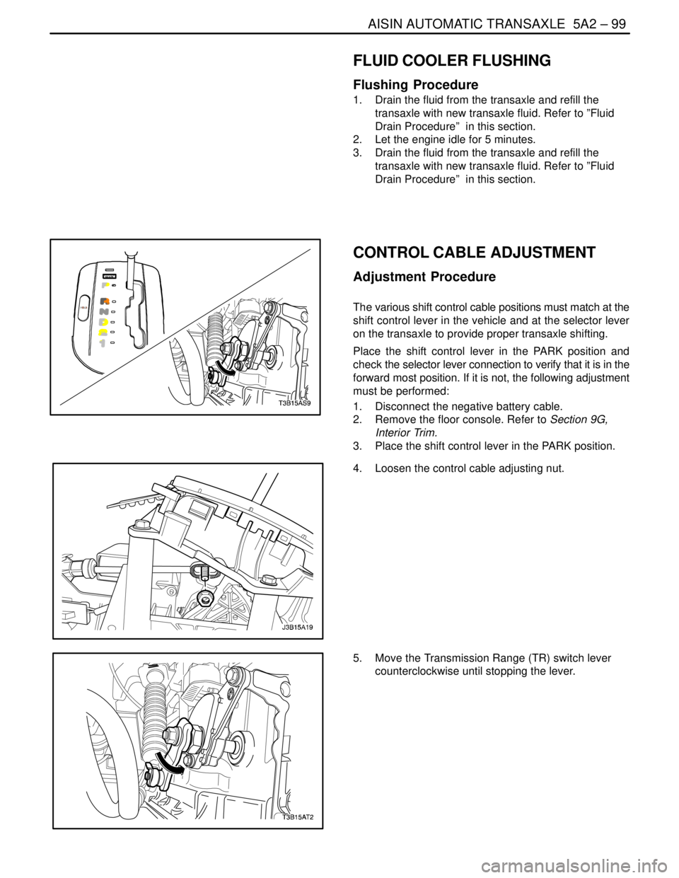
The various shift control cable positions must match at the
shift control lever in the vehicle and at the selector lever
on the transaxle to provide proper transaxle shifting.
Place the shift control lever in the PARK position and
check the selector lever connection to verify that it is in the
forward most position. If it is not, the following adjustment
must be performed:
1. Disconnect the negative battery cable.
2. Remove the floor console. Refer to Section 9G,
Interior Trim.
3. Place the shift control lever in the PARK position.
4. Loosen the control cable adjusting nut.
5. Move the Transmission Range (TR) switch lever
counterclockwise until stopping the lever.
Page 1692 of 2643

5A2 – 102IAISIN AUTOMATIC TRANSAXLE
DAEWOO V–121 BL4
3. Remove the E–ring.
4. Disconnect the shift control cable from the TR
switch lever.
5. Remove the retaining nut and then remove the
washer and the control lever.
6. Using a driver, unstake the lock washer and re-
move the nut.
Installation Procedure
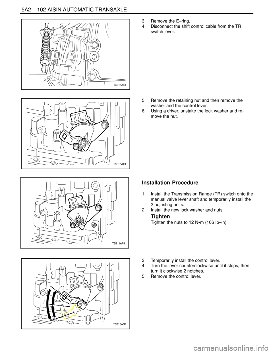
1. Install the Transmission Range (TR) switch onto the
manual valve lever shaft and temporarily install the
2 adjusting bolts.
2. Install the new lock washer and nuts.
Tighten
Tighten the nuts to 12 NSm (106 Ib–in).
3. Temporarily install the control lever.
4. Turn the lever counterclockwise until it stops, then
turn it clockwise 2 notches.
5. Remove the control lever.
Page 1740 of 2643

5A2 – 150IAISIN AUTOMATIC TRANSAXLE
DAEWOO V–121 BL4
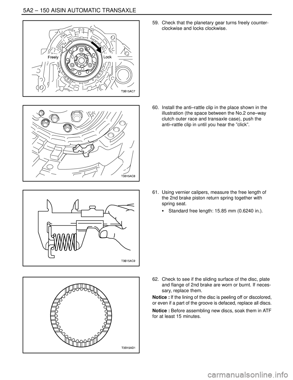
59. Check that the planetary gear turns freely counter-
clockwise and locks clockwise.
60. Install the anti–rattle clip in the place shown in the
illustration (the space between the No.2 one–way
clutch outer race and transaxle case), push the
anti–rattle clip in until you hear the ”click”.
61. Using vernier calipers, measure the free length of
the 2nd brake piston return spring together with
spring seat.
S Standard free length: 15.85 mm (0.6240 in.).
62. Check to see if the sliding surface of the disc, plate
and flange of 2nd brake are worn or burnt. If neces-
sary, replace them.
Notice : If the lining of the disc is peeling off or discolored,
or even if a part of the groove is defaced, replace all discs.
Notice : Before assembling new discs, soak them in ATF
for at least 15 minutes.