Page 149 of 2643
1.8L DOHC ENGINE MECHANICAL 1C2 – 29
DAEWOO V–121 BL4
15. Using the crankshaft gear bolt, rotate the crank-
shaft clockwise until the timing mark on the crank-
shaft gear is aligned with the notch at the bottom of
the rear timing belt cover.
Notice : The camshaft gears must align with the notch on
the camshaft cover or damage to the engine could result.
16. Align the camshaft gears with the notch on the
camshaft cover.
Important : Use the intake gear mark for the intake cam-
shaft gear and the exhaust gear mark for the exhaust cam-
shaft gear since both gears are interchangeable.
17. Remove the timing belt.
18. Loosen the automatic tensioner bolt. Turn the hex–
key tab to relieve belt tension.
Installation Procedure
1. Align the timing mark on the crankshaft gear with
the notch on the bottom of the rear timing belt cov-
er.
Page 150 of 2643
1C2 – 30I1.8L DOHC ENGINE MECHANICAL
DAEWOO V–121 BL4
2. Align the timing marks on the camshaft gears, us-
ing the intake gear mark for the intake gear and the
exhaust gear mark for the exhaust gear.
3. Install the timing belt.
4. Turn the hex–key tab in a clockwise direction to
tension the belt. Turn until the pointer aligns with
the notch.
5. Install the automatic tensioner bolt.
Tighten
Tighten the automatic tensioner bolt to 25 NSm (18 lb–
ft).
6. Rotate the crankshaft two full turns clockwise using
the crankshaft pulley bolt.
7. Recheck the automatic tensioner pointer.
8. Install the front timing belt cover.
9. Install the front timing belt cover bolts.
Tighten
Tighten the front timing belt cover bolts to 6 NSm (53
lb–in).
10. Install the right engine mount bracket. Refer to ”En-
gine Mounts” in this section.
Page 158 of 2643

1C2 – 38I1.8L DOHC ENGINE MECHANICAL
DAEWOO V–121 BL4
3. Install the timing belt idler pulleys.
4. Install the timing belt idler pulley bolt and nut.
Tighten
Tighten the timing belt idler pulley bolt and nut to 25
NSm (18 lb–ft).
5. Tension the timing belt by turning the timing belt
automatic tensioner hex–key tab counterclockwise
until the pointer is aligned to the indicator.
Tighten
Tighten the timing belt automatic tensioner bolt to 25
NSm (18 lb–ft).
6. Install the front timing belt cover.
7. Install the front timing belt cover bolts.
Tighten
Tighten the front timing belt cover bolts to 6 NSm (53
lb–in).
8. Install the engine mount bracket and retaining bolts.
Tighten
Tighten the engine mount bracket retaining bolts to 55
NSm (41 lb–ft).
9. Remove the engine assembly support fixture
J–28467–B, and the channel X–28467–560.
10. Install the serpentine accessory drive belt. Refer to
Section 6B, Power Steering Pump.
11. Connect the negative battery cable.
INTAKE MANIFOLD
Removal Procedure
1. Remove the fuel pump fuse.
2. Start the engine. After it stalls, crank the engine for
10 seconds to rid the fuel system of fuel pressure.
3. Disconnect the negative battery cable.
4. Disconnect the charcoal canister purge (CCP) and
exhaust gas recirculation (EGR) solenoid from the
intake manifold and loosen the bracket bolt.
5. Drain the engine coolant. Refer to Section 1D, En-
gine Cooling.
6. Disconnect the manifold air temperature sensor
(MAT) connector.
7. Disconnect the air cleaner outlet hose from the
throttle body.
Page 184 of 2643

1C2 – 64I1.8L DOHC ENGINE MECHANICAL
DAEWOO V–121 BL4
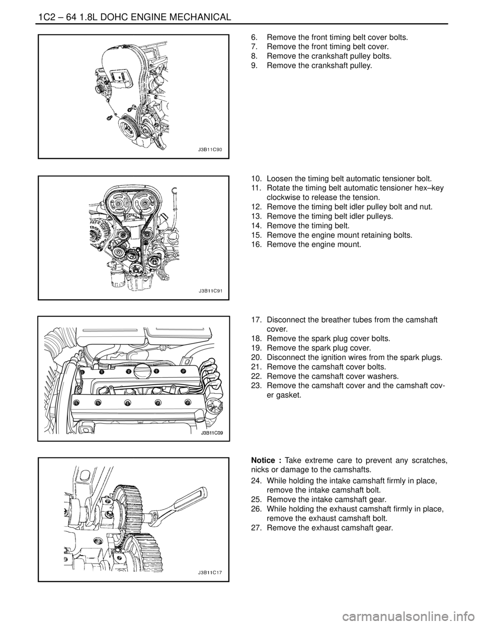
6. Remove the front timing belt cover bolts.
7. Remove the front timing belt cover.
8. Remove the crankshaft pulley bolts.
9. Remove the crankshaft pulley.
10. Loosen the timing belt automatic tensioner bolt.
11. Rotate the timing belt automatic tensioner hex–key
clockwise to release the tension.
12. Remove the timing belt idler pulley bolt and nut.
13. Remove the timing belt idler pulleys.
14. Remove the timing belt.
15. Remove the engine mount retaining bolts.
16. Remove the engine mount.
17. Disconnect the breather tubes from the camshaft
cover.
18. Remove the spark plug cover bolts.
19. Remove the spark plug cover.
20. Disconnect the ignition wires from the spark plugs.
21. Remove the camshaft cover bolts.
22. Remove the camshaft cover washers.
23. Remove the camshaft cover and the camshaft cov-
er gasket.
Notice : Take extreme care to prevent any scratches,
nicks or damage to the camshafts.
24. While holding the intake camshaft firmly in place,
remove the intake camshaft bolt.
25. Remove the intake camshaft gear.
26. While holding the exhaust camshaft firmly in place,
remove the exhaust camshaft bolt.
27. Remove the exhaust camshaft gear.
Page 205 of 2643

1D – 10IENGINE COOLING
DAEWOO V–121 BL4
4. Connect the upper radiator hose to the thermostat
housing.
5. Secure the upper radiator hose to the thermostat
housing with a hose clamp.
6. Connect the bypass hose to the thermostat hous-
ing.
7. Secure the bypass hose with a hose clamp.
8. Refill the engine cooling system. Refer to ”Draining
and Refilling the Cooling System” in this section.
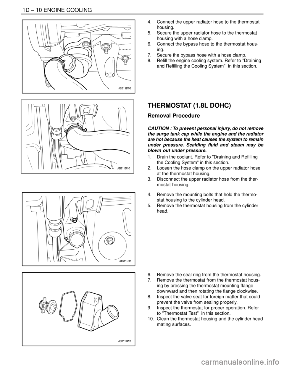
THERMOSTAT (1.8L DOHC)
Removal Procedure
CAUTION : To prevent personal injury, do not remove
the surge tank cap while the engine and the radiator
are hot because the heat causes the system to remain
under pressure. Scalding fluid and steam may be
blown out under pressure.
1. Drain the coolant. Refer to ”Draining and Refilling
the Cooling System” in this section.
2. Loosen the hose clamp on the upper radiator hose
at the thermostat housing.
3. Disconnect the upper radiator hose from the ther-
mostat housing.
4. Remove the mounting bolts that hold the thermo-
stat housing to the cylinder head.
5. Remove the thermostat housing from the cylinder
head.
6. Remove the seal ring from the thermostat housing.
7. Remove the thermostat from the thermostat hous-
ing by pressing the thermostat mounting flange
downward and then rotating the flange clockwise.
8. Inspect the valve seat for foreign matter that could
prevent the valve from sealing properly.
9. Inspect the thermostat for proper operation. Refer
to ”Thermostat Test” in this section.
10. Clean the thermostat housing and the cylinder head
mating surfaces.
Page 206 of 2643

ENGINE COOLING 1D – 11
DAEWOO V–121 BL4
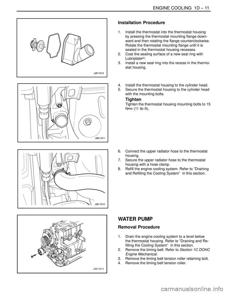
Installation Procedure
1. Install the thermostat into the thermostat housing
by pressing the thermostat mounting flange down-
ward and then rotating the flange counterclockwise.
Rotate the thermostat mounting flange until it is
seated in the thermostat housing recesses.
2. Coat the sealing surface of a new seal ring with
Lubriplater®.
3. Install a new seal ring into the recess in the thermo-
stat housing.
4. Install the thermostat housing to the cylinder head.
5. Secure the thermostat housing to the cylinder head
with the mounting bolts.
Tighten
Tighten the thermostat housing mounting bolts to 15
NSm (11 lb–ft).
6. Connect the upper radiator hose to the thermostat
housing.
7. Secure the upper radiator hose to the thermostat
housing with a hose clamp.
8. Refill the engine cooling system. Refer to ”Draining
and Refilling the Cooling System” in this section.
WATER PUMP
Removal Procedure
1. Drain the engine cooling system to a level below
the thermostat housing. Refer to ”Draining and Re-
filling the Cooling System” in this section.
2. Remove the timing belt. Refer to Section 1C DOHC
Engine Mechanical.
3. Remove the timing belt tension roller retaining bolt.
4. Remove the timing belt tension roller.
Page 225 of 2643
ENGINE ELECTRICAL 1E – 11
DAEWOO V–121 BL4
MAINTENANCE AND REPAIR
ON–VEHICLE SERVICE
GENERATOR
Removal Procedure
1. Disconnect the negative battery cable.
2. Disconnect the manifold air temperature (MAT)
sensor electrical connector the air intake tube.
3. Remove all the clamps from the air cleaner outlet
hose, and set aside the tube.
4. Raise and suitably support the vehicle.
5. Disconnect the harness connector from the back of
the generator, and the generator lead to the battery.
6. Remove the serpentine accessory drive belt by low-
ering the vehicle and turning the automatic tension-
er roller bolt clockwise to relieve tension on the belt.
Refer to Section 6B, Power Steering Pump.
7. Push up the power steering reservoir and set it
aside.
8. Remove the bolt of the generator upper engine con-
necting bracket to the 1.4L/1.6L engine.
Page 409 of 2643

ENGINE CONTROLS 1F – 163
DAEWOO V–121 BL4
StepNo Yes Value(s) Action
3With the engine running, operate the vehicle until the
LOOP STATUS indicates closed.
Is the Long Term Fuel Trim value above the specified
value?–30%Go to Step 4Go to Step 5
41. Turn the ignition switch ON, with the engine
OFF.
2. Review the Freeze Frame data and note the
parameters.
3. Operate the vehicle within the Freeze Frame
conditions and Conditions for Setting The DTC
as noted.
Does the Long Term Fuel Trim value above the spe-
cified value while operating under the specified con-
ditions?–30%Go to Step 21Go to Step 5
5Visually/physically check the air cleaner filter for ex-
cessive dirt or being plugged and repair as needed.
Is the repair complete?–Go to Step 21Go to Step 6
6Visually/physically check the air intake system for
collapsed or restricted and repair as needed.
Is the repair complete?–Go to Step 21Go to Step 7
7Inspect the throttle body inlet for damaged or foreign
objects which may partially block the airflow and re-
pair as needed.
Is the repair complete?–Go to Step 21Go to Step 8
81. Turn the ignition OFF.
2. Inspect the throttle bore, throttle plate and Idle
Air Control (IAC) passages for clocking and
foreign objects and repair as needed.
Is the repair complete?–Go to Step 21Go to Step 9
9Start the engine with the vehicle in park or neutral
and A/C off and note the idle quality.
Is a low or unsteady idle being experienced?–Go to Step 10Go to Step 12
10Idle the engine.
Are the IAC counts below the specified value?100Go to Step 12Go to Step 11
111. Turn the ignition OFF.
2. Disconnect the Manifold Absolute Pressure
(MAP) sensor electrical connector.
3. Start the engine.
4. Operate the vehicle in Closed Loop while moni-
toring the Long Term Fuel Trim value.
Does the Long Term Fuel Trim value increase above
the specified value?–30%Go to Step 20Go to Step 12
12Check the IAC valve performance. Refer to ”DTC
P0506 Idle Speed RPM Lower Than Desired Idle
Speed” or ”DTC P0507 Idle Speed RPM Higher
Than Desired Idle Speed” in this section and repair
as necessary.
Is the repair complete?–Go to Step 21Go to Step 13