2004 DAEWOO NUBIRA Fender
[x] Cancel search: FenderPage 2546 of 2643
4–12 FRONTNUBIRA/LACETTI
Note : Use of jigs is recommended for correct positions
and check that the both front longitudinal and wheel-
house are parallel.
S Tack weld the clamped section for temporary installa-
tion.
7. Perform the main welding.
S Weld as much as possible with the jig still mounted.
S Make MIG or gas welds at the butt joints at the front lon-
gitudinal, carefully.
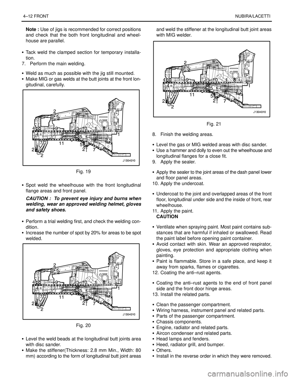
Fig. 19
S Spot weld the wheelhouse with the front longitudinal
flange areas and front panel.
CAUTION : To prevent eye injury and burns when
welding, wear an approved welding helmet, gloves
and safety shoes.
S Perform a trial welding first, and check the welding con-
dition.
S Increase the number of spot by 20% for areas to be spot
welded.
Fig. 20
S Level the weld beads at the longitudinal butt joints area
with disc sander.
S Make the stiffener(Thickness: 2.8 mm Min., Width: 80
mm) according to the form of longitudinal butt joint areasand weld the stiffener at the longitudinal butt joint areas
with MIG welder.
Fig. 21
8. Finish the welding areas.
S Level the gas or MIG welded areas with disc sander.
S Use a hammer and dolly to even out the wheelhouse and
longitudinal flanges for a close fit.
9. Apply the sealer.
S Apply the sealer to the joint areas of the dash panel lower
and floor panel areas.
10. Apply the undercoat.
S Undercoat to the joint and overlapped areas of the front
floor, longitudinal under side and the inside of front, rear
wheelhouse.
11. Apply the paint.
CAUTION
S Ventilate when spraying paint. Most paint contains sub-
stances that are harmful if inhaled or swallowed. Read
the paint label before opening paint container.
S Avoid contact with skin. Wear an approved respirator,
gloves, eye protection and appropriate clothing when
painting.
S Paint is flammable. Store in a safe place, and keep it
away from sparks, flames or cigarettes.
12. Coating the anti–rust agents.
S Coating the anti–rust agents to the end of front panel
side and the front door hinge areas.
13. Install the related parts.
S Clean the passenger compartment.
S Wiring harness, instrument panel and related parts.
S Parts of the passenger compartment.
S Chassis components.
S Engine, radiator and related parts.
S Aircon condenser and related parts.
S Head lamps and fenders.
S Heed, radiator grill, and bumper.
S Others.
S Install in the reverse order in which they were removed.
Page 2548 of 2643
4–14 FRONTNUBIRA/LACETTI
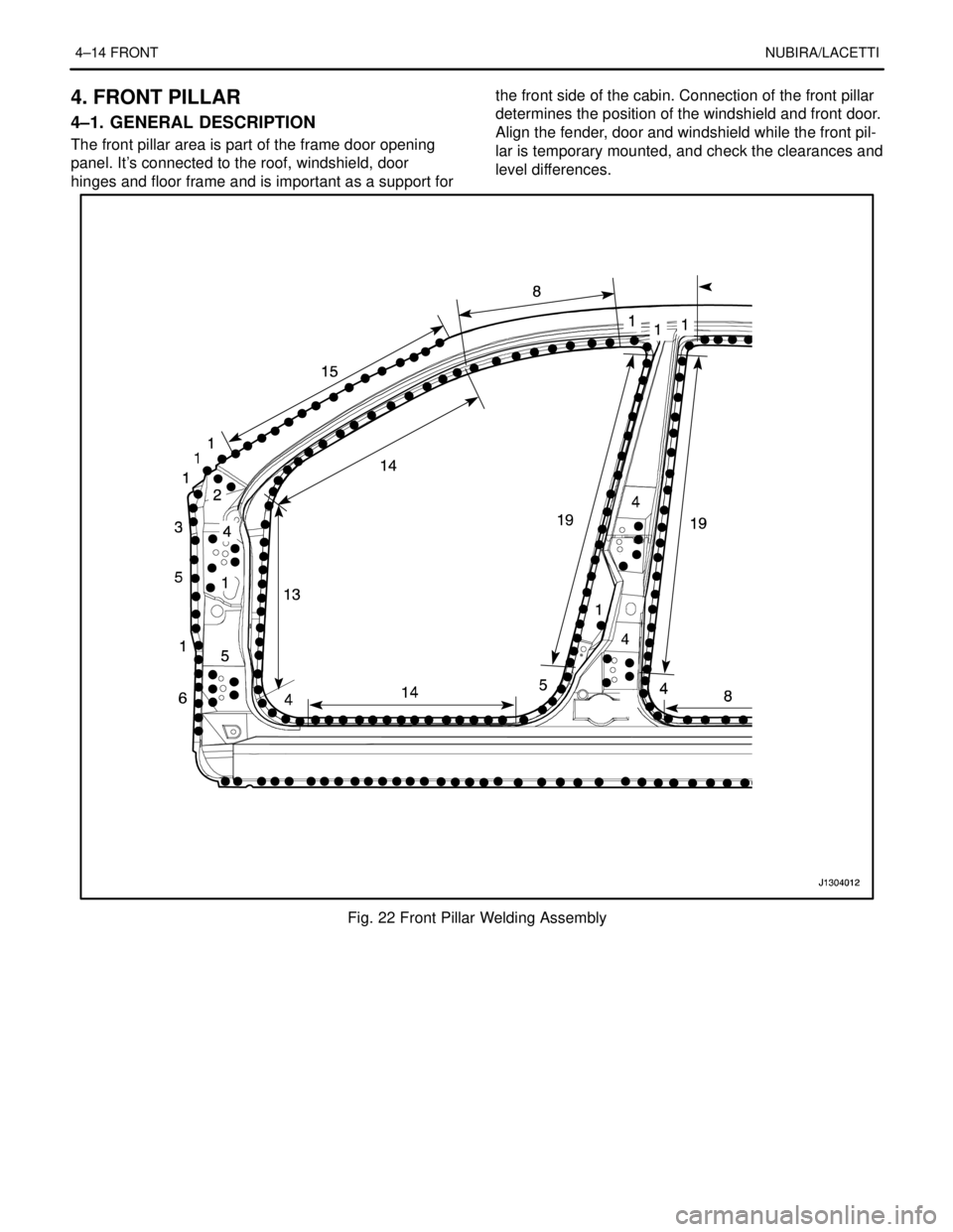
4. FRONT PILLAR
4–1. GENERAL DESCRIPTION
The front pillar area is part of the frame door opening
panel. It’s connected to the roof, windshield, door
hinges and floor frame and is important as a support forthe front side of the cabin. Connection of the front pillar
determines the position of the windshield and front door.
Align the fender, door and windshield while the front pil-
lar is temporary mounted, and check the clearances and
level differences.
Fig. 22 Front Pillar Welding Assembly
Page 2549 of 2643
NUBIRA/LACETTIFRONT 4–15
4–2. REPAIR PROCEDURE
1. Remove the related parts.
S Hood, radiator grill and front bumper.
S Door and fender.
S Wiper, cowl and windshield.
S Weatherstrip and pillar trims.
S Instrument panel and wiring harness.
S Carpet and others.
2. Roughly pull out and straighten the damaged area.
S Check the damage to the wheelhouse and roof before
removing the brace wheelhouse and front pillar and de-
termine the extent of the damage.
S Use the frame straightener to roughly pull out and repair
the damaged front pillar before removing the brace
wheelhouse and front panel.
Note : Pull out until the pillar is lined up with the surface
of the windshield and do not pull out more than neces-
sary.
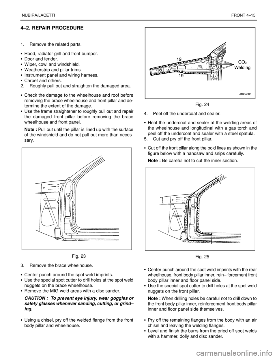
Fig. 23
3. Remove the brace wheelhouse.
S Center punch around the spot weld imprints.
S Use the special spot cutter to drill holes at the spot weld
nuggets on the brace wheelhouse.
S Remove the MIG weld areas with a disc sander.
CAUTION : To prevent eye injury, wear goggles or
safety glasses whenever sanding, cutting, or grind–
ing.
S Using a chisel, pry off the welded flange from the front
body pillar and wheelhouse.
Fig. 24
4. Peel off the undercoat and sealer.
S Heat the undercoat and sealer at the welding areas of
the wheelhouse and longitudinal with a gas torch and
peel off the undercoat and sealer with a steel spatula.
5. Cut and pry off the front pillar.
S Cut off the front pillar along the bold lines as shown in the
figure below with a handsaw and snips carefully.
Note : Be careful not to cut the inner section.
Fig. 25
S Center punch around the spot weld imprints with the rear
wheelhouse, front body pillar inner, rein– forcement front
body pillar inner and floor panel side.
S Use the special spot cutter to drill holes at the spot weld
nuggets on the front pillar.
Note : When drilling holes be careful not to drill down to
the front body pillar inner, reinforcement front body pillar
inner and floor panel side themselves.
S Pry off the remaining flanges from the body with an air
chisel and leaving the welding flanges.
S Level and finish the burrs from the pried off spot welds
with a hammer, dolly and disc sander.
Page 2550 of 2643
4–16 FRONTNUBIRA/LACETTI
CAUTION : To prevent eye injury, wear goggles or
safety glasses whenever sanding, cutting, or grind–
ing.
6. Mold damaged related parts.
S Fill any holes drilled by welding.
CAUTION : To prevent eye injury and burns when
welding, wear an approved welding helmet, gloves
and safety shoes.
S Use a hammer and dolly to mold damaged areas of the
remaining inner panel and even out the welding flanges.
7. Set the new front pillar.
S Align the new part with the top section, then cut it with
a hand saw.
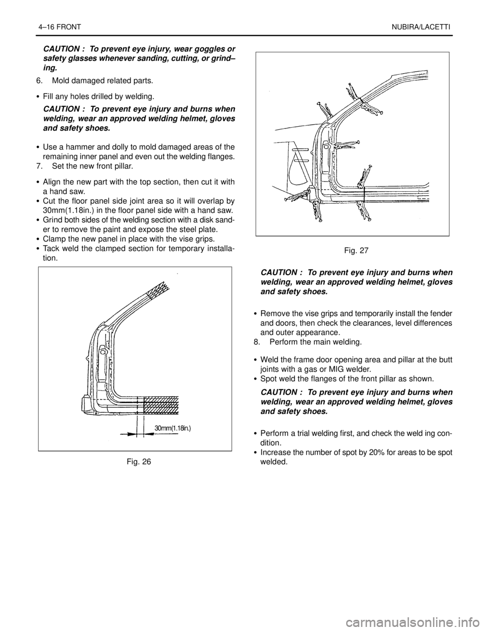
S Cut the floor panel side joint area so it will overlap by
30mm(1.18in.) in the floor panel side with a hand saw.
S Grind both sides of the welding section with a disk sand-
er to remove the paint and expose the steel plate.
S Clamp the new panel in place with the vise grips.
S Tack weld the clamped section for temporary installa-
tion.
Fig. 26
Fig. 27
CAUTION : To prevent eye injury and burns when
welding, wear an approved welding helmet, gloves
and safety shoes.
S Remove the vise grips and temporarily install the fender
and doors, then check the clearances, level differences
and outer appearance.
8. Perform the main welding.
S Weld the frame door opening area and pillar at the butt
joints with a gas or MIG welder.
S Spot weld the flanges of the front pillar as shown.
CAUTION : To prevent eye injury and burns when
welding, wear an approved welding helmet, gloves
and safety shoes.
S Perform a trial welding first, and check the weld ing con-
dition.
S Increase the number of spot by 20% for areas to be spot
welded.
Page 2551 of 2643
NUBIRA/LACETTIFRONT 4–17
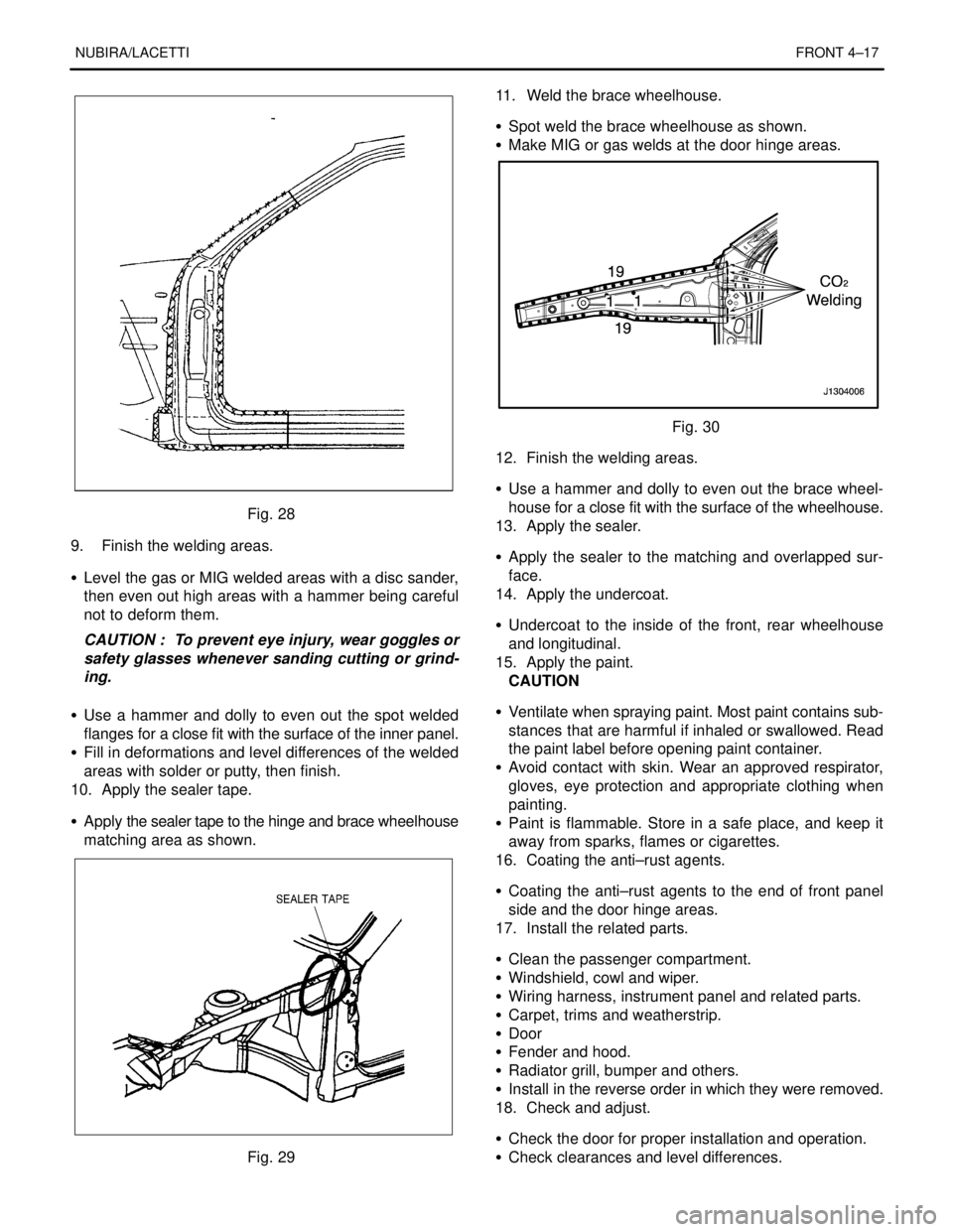
Fig. 28
9. Finish the welding areas.
S Level the gas or MIG welded areas with a disc sander,
then even out high areas with a hammer being careful
not to deform them.
CAUTION : To prevent eye injury, wear goggles or
safety glasses whenever sanding cutting or grind-
ing.
S Use a hammer and dolly to even out the spot welded
flanges for a close fit with the surface of the inner panel.
S Fill in deformations and level differences of the welded
areas with solder or putty, then finish.
10. Apply the sealer tape.
S Apply the sealer tape to the hinge and brace wheelhouse
matching area as shown.
Fig. 2911. Weld the brace wheelhouse.
S Spot weld the brace wheelhouse as shown.
S Make MIG or gas welds at the door hinge areas.
Fig. 30
12. Finish the welding areas.
S Use a hammer and dolly to even out the brace wheel-
house for a close fit with the surface of the wheelhouse.
13. Apply the sealer.
S Apply the sealer to the matching and overlapped sur-
face.
14. Apply the undercoat.
S Undercoat to the inside of the front, rear wheelhouse
and longitudinal.
15. Apply the paint.
CAUTION
S Ventilate when spraying paint. Most paint contains sub-
stances that are harmful if inhaled or swallowed. Read
the paint label before opening paint container.
S Avoid contact with skin. Wear an approved respirator,
gloves, eye protection and appropriate clothing when
painting.
S Paint is flammable. Store in a safe place, and keep it
away from sparks, flames or cigarettes.
16. Coating the anti–rust agents.
S Coating the anti–rust agents to the end of front panel
side and the door hinge areas.
17. Install the related parts.
S Clean the passenger compartment.
S Windshield, cowl and wiper.
S Wiring harness, instrument panel and related parts.
S Carpet, trims and weatherstrip.
S Door
S Fender and hood.
S Radiator grill, bumper and others.
S Install in the reverse order in which they were removed.
18. Check and adjust.
S Check the door for proper installation and operation.
S Check clearances and level differences.
Page 2569 of 2643
6–4 FRAME DOOR OPENING, DOOR AND SIDE PANEL OUTER NUBIRA/LACETTI
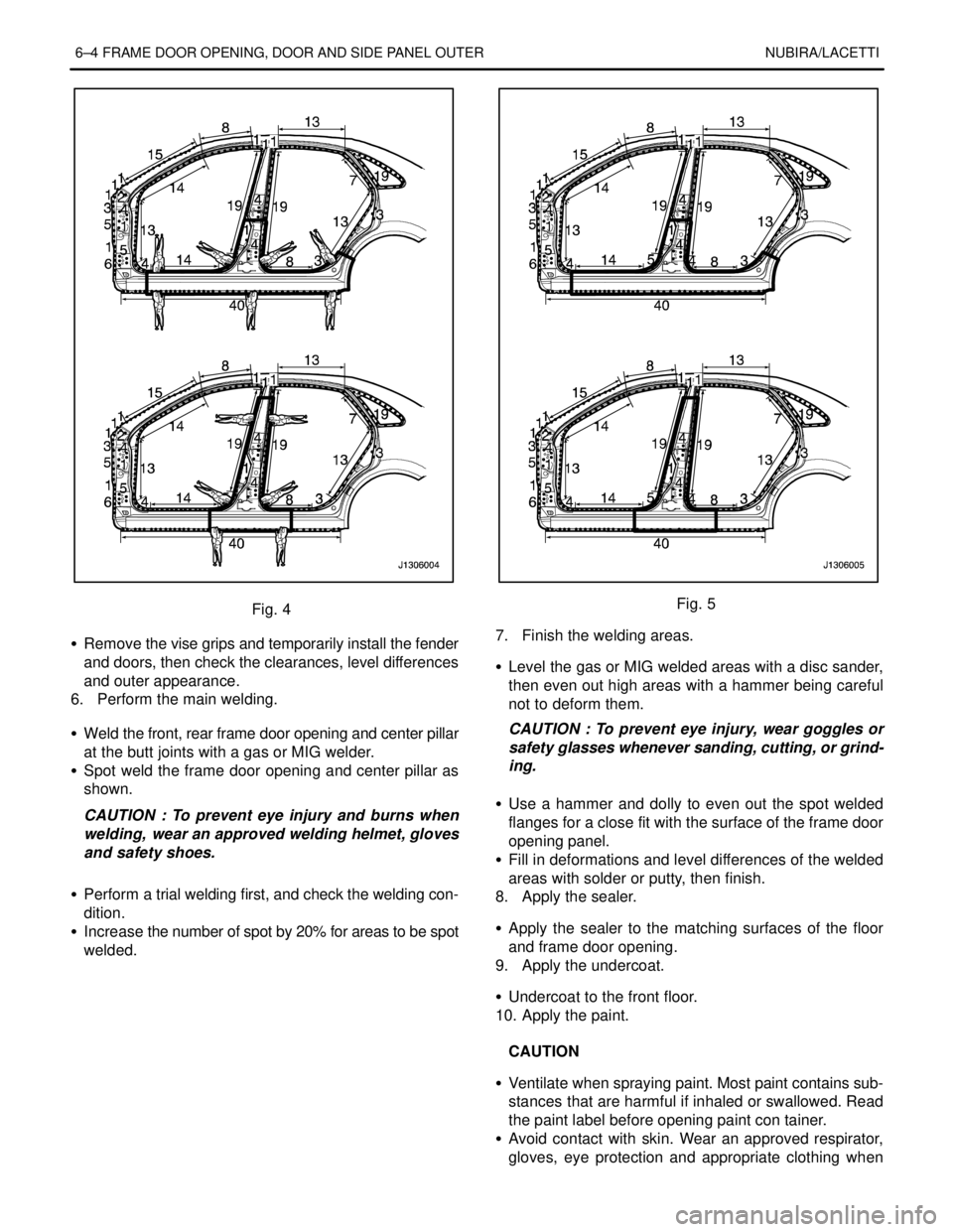
Fig. 4
S Remove the vise grips and temporarily install the fender
and doors, then check the clearances, level differences
and outer appearance.
6. Perform the main welding.
S Weld the front, rear frame door opening and center pillar
at the butt joints with a gas or MIG welder.
S Spot weld the frame door opening and center pillar as
shown.
CAUTION : To prevent eye injury and burns when
welding, wear an approved welding helmet, gloves
and safety shoes.
S Perform a trial welding first, and check the welding con-
dition.
S Increase the number of spot by 20% for areas to be spot
welded.Fig. 5
7. Finish the welding areas.
S Level the gas or MIG welded areas with a disc sander,
then even out high areas with a hammer being careful
not to deform them.
CAUTION : To prevent eye injury, wear goggles or
safety glasses whenever sanding, cutting, or grind-
ing.
S Use a hammer and dolly to even out the spot welded
flanges for a close fit with the surface of the frame door
opening panel.
S Fill in deformations and level differences of the welded
areas with solder or putty, then finish.
8. Apply the sealer.
S Apply the sealer to the matching surfaces of the floor
and frame door opening.
9. Apply the undercoat.
S Undercoat to the front floor.
10. Apply the paint.
CAUTION
S Ventilate when spraying paint. Most paint contains sub-
stances that are harmful if inhaled or swallowed. Read
the paint label before opening paint con tainer.
S Avoid contact with skin. Wear an approved respirator,
gloves, eye protection and appropriate clothing when
Page 2571 of 2643
6–6 FRAME DOOR OPENING, DOOR AND SIDE PANEL OUTER NUBIRA/LACETTI
2. DOOR
2–1. REPAIR PROCEDURE
1. Remove the related parts.
S Door trim and related parts.
S Wiring harness and solenoid valve.
S Glass and window lifter.
S Linkage, lock set and handle.
S Others.
Note : Inspection and choose the usable parts.
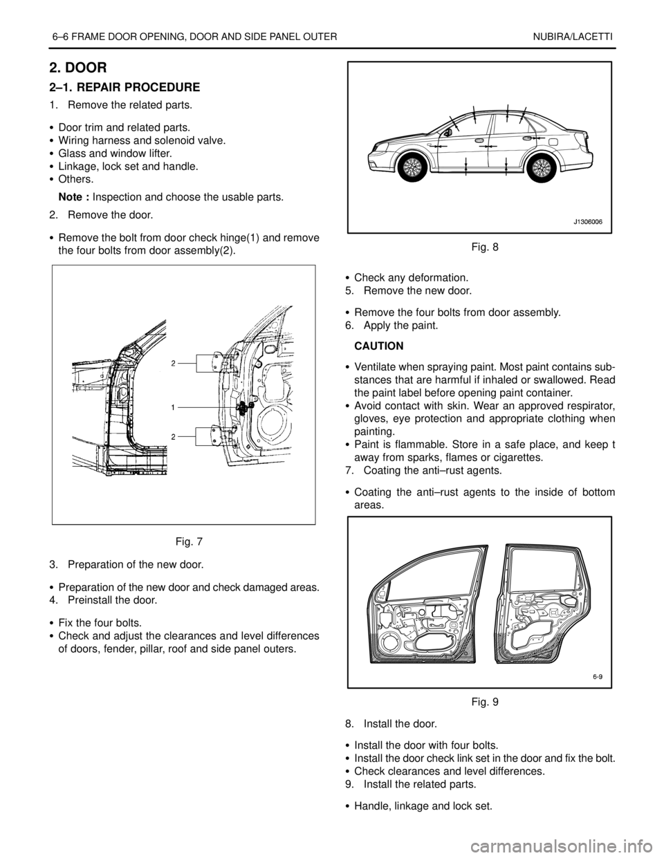
2. Remove the door.
S Remove the bolt from door check hinge(1) and remove
the four bolts from door assembly(2).
Fig. 7
3. Preparation of the new door.
S Preparation of the new door and check damaged areas.
4. Preinstall the door.
S Fix the four bolts.
S Check and adjust the clearances and level differences
of doors, fender, pillar, roof and side panel outers.
Fig. 8
S Check any deformation.
5. Remove the new door.
S Remove the four bolts from door assembly.
6. Apply the paint.
CAUTION
S Ventilate when spraying paint. Most paint contains sub-
stances that are harmful if inhaled or swallowed. Read
the paint label before opening paint container.
S Avoid contact with skin. Wear an approved respirator,
gloves, eye protection and appropriate clothing when
painting.
S Paint is flammable. Store in a safe place, and keep t
away from sparks, flames or cigarettes.
7. Coating the anti–rust agents.
S Coating the anti–rust agents to the inside of bottom
areas.
Fig. 9
8. Install the door.
S Install the door with four bolts.
S Install the door check link set in the door and fix the bolt.
S Check clearances and level differences.
9. Install the related parts.
S Handle, linkage and lock set.
Page 2578 of 2643

NUBIRA/LACETTI FENDER, HOOD, TAILGATE AND TRUNK LID 7–1
SECTION 7
FENDER, HOOD, TAILGATE AND TRUNK LID
CONTENTS
1. FENDER 7 – 2. . . . . . . . . . . . . . . . . . . . . . . . . . . . . . . . . . . . . . . . . . . . . . . . . . . . . . . . . . .
1.1.REPAIR PROCEDURE7–2 . . . . . . . . . . . . . . . . . . . . . . . . . . . . . . . . . . . . . . . . . . . . . . . . . . . . . . . . . . . . . . . . . . . . . . . . . .
2. HOOD 7 – 3. . . . . . . . . . . . . . . . . . . . . . . . . . . . . . . . . . . . . . . . . . . . . . . . . . . . . . . . . . . . .
2.1.REPAIR PROCEDURE7–3 . . . . . . . . . . . . . . . . . . . . . . . . . . . . . . . . . . . . . . . . . . . . . . . . . . . . . . . . . . . . . . . . . . . . . . . . . .
3. TAILGATE(HATCHBACK) 7 – 4. . . . . . . . . . . . . . . . . . . . . . . . . . . . . . . . . . . . . . . . . . .
3.1.REPAIR PROCEDURE7–4 . . . . . . . . . . . . . . . . . . . . . . . . . . . . . . . . . . . . . . . . . . . . . . . . . . . . . . . . . . . . . . . . . . . . . . . . . .
4. TRUNK LID (NOTCHBACK) 7 – 5. . . . . . . . . . . . . . . . . . . . . . . . . . . . . . . . . . . . . . . . .
4.1.REPAIR PROCEDURE7–5 . . . . . . . . . . . . . . . . . . . . . . . . . . . . . . . . . . . . . . . . . . . . . . . . . . . . . . . . . . . . . . . . . . . . . . . . . .