Page 1143 of 2643

4F – 62IANTILOCK BRAKE SYSTEM
DAEWOO V–121 BL4
FRONT WHEEL SPEED SENSOR
Removal Procedure
1. Disconnect the negative battery cable.
2. Disconnect the front wheel speed sensor electrical
connector.
3. Raise and suitably support the vehicle.
4. Remove the wheel. Refer to Section 2E, Tires and
Wheels.
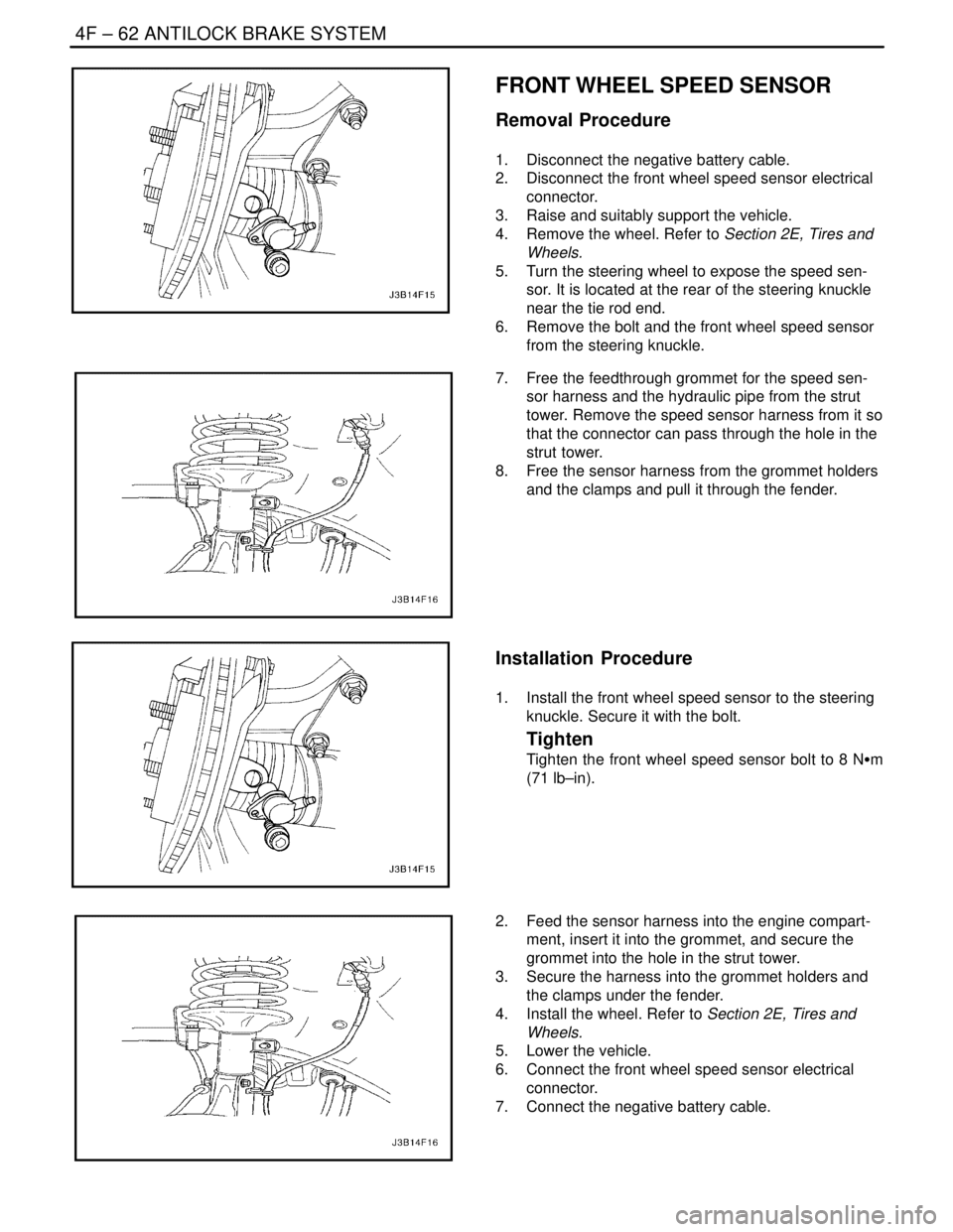
5. Turn the steering wheel to expose the speed sen-
sor. It is located at the rear of the steering knuckle
near the tie rod end.
6. Remove the bolt and the front wheel speed sensor
from the steering knuckle.
7. Free the feedthrough grommet for the speed sen-
sor harness and the hydraulic pipe from the strut
tower. Remove the speed sensor harness from it so
that the connector can pass through the hole in the
strut tower.
8. Free the sensor harness from the grommet holders
and the clamps and pull it through the fender.
Installation Procedure
1. Install the front wheel speed sensor to the steering
knuckle. Secure it with the bolt.
Tighten
Tighten the front wheel speed sensor bolt to 8 NSm
(71 lb–in).
2. Feed the sensor harness into the engine compart-
ment, insert it into the grommet, and secure the
grommet into the hole in the strut tower.
3. Secure the harness into the grommet holders and
the clamps under the fender.
4. Install the wheel. Refer to Section 2E, Tires and
Wheels.
5. Lower the vehicle.
6. Connect the front wheel speed sensor electrical
connector.
7. Connect the negative battery cable.
Page 1144 of 2643

ANTILOCK BRAKE SYSTEM 4F – 63
DAEWOO V–121 BL4
FRONT WHEEL SPEED SENSOR
JUMPER HARNESS
(Left–Hand Drive Shown, Right–Hand Drive
Similar)
Removal Procedure
1. Disconnect the negative battery cable.
2. Disconnect connector from the EBCM.
3. Remove the appropriate terminals from connector:
S Right–side – terminals 4 (WHT) and 5 (GRY).
S Left–side – terminals 6 (BRN) and 7 (LT BLU).
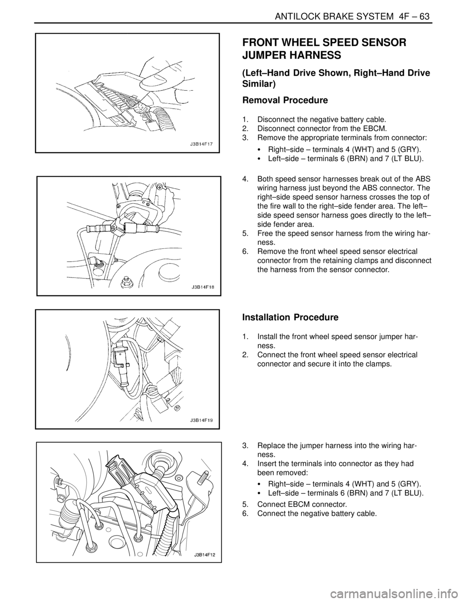
4. Both speed sensor harnesses break out of the ABS
wiring harness just beyond the ABS connector. The
right–side speed sensor harness crosses the top of
the fire wall to the right–side fender area. The left–
side speed sensor harness goes directly to the left–
side fender area.
5. Free the speed sensor harness from the wiring har-
ness.
6. Remove the front wheel speed sensor electrical
connector from the retaining clamps and disconnect
the harness from the sensor connector.
Installation Procedure
1. Install the front wheel speed sensor jumper har-
ness.
2. Connect the front wheel speed sensor electrical
connector and secure it into the clamps.
3. Replace the jumper harness into the wiring har-
ness.
4. Insert the terminals into connector as they had
been removed:
S Right–side – terminals 4 (WHT) and 5 (GRY).
S Left–side – terminals 6 (BRN) and 7 (LT BLU).
5. Connect EBCM connector.
6. Connect the negative battery cable.
Page 2412 of 2643

SECTION : 9O
BUMPERS AND FASCIAS
CAUTION : Disconnect the negative battery cable before removing or installing any electrical unit or when a tool
or equipment could easily come in contact with exposed electrical terminals. Disconnecting this cable will help
prevent personal injury and damage to the vehicle. The ignition must also be in LOCK unless otherwise noted.
TABLE OF CONTENTS
SPECIFICATIONS9O–1 . . . . . . . . . . . . . . . . . . . . . . . . . .
Fastener Tightening Specifications 9O–1. . . . . . . . . . .
MAINTENANCE AND REPAIR9O–2 . . . . . . . . . . . . . . .
ON–VEHICLE SERVICE 9O–2. . . . . . . . . . . . . . . . . . . . .
Front Bumper Fascia 9O–2. . . . . . . . . . . . . . . . . . . . . . .
Front Bumper Energy Absorber 9O–3. . . . . . . . . . . . . . Front Bumper Impact Bar 9O–4. . . . . . . . . . . . . . . . . . .
Notchback Rear Bumper Fascia 9O–4. . . . . . . . . . . . .
Hatchback Rear Bumper Fascia 9O–6. . . . . . . . . . . . .
Rear Bumper Impact Bar 9O–7. . . . . . . . . . . . . . . . . . .
GENERAL DESCRIPTION AND SYSTEM
OPERATION9O–9 . . . . . . . . . . . . . . . . . . . . . . . . . . . . . .
Bumpers 9O–9. . . . . . . . . . . . . . . . . . . . . . . . . . . . . . . . .
SPECIFICATIONS
FASTENER TIGHTENING SPECIFICATIONS
ApplicationNSmLb–FtLb–In
Fender–to–Fascia Bolts10–89
Fender–to–Fascia Screws2–18
Front Impact Bar Bolts3929–
Lower Fascia Screws2–18
Luggage Compartment Fascia Bolts10–89
Luggage Compartment Fascia Screws2–18
Rear Wheel Well Fascia Bolts2–18
Page 2413 of 2643
9O – 2IBUMPERS AND FASCIAS
DAEWOO V–121 BL4
MAINTENANCE AND REPAIR
ON–VEHICLE SERVICE
FRONT BUMPER FASCIA
Removal Procedure
1. Disconnect the negative battery cable.
2. Remove the front wheel well splash shields. Refer
to Section 9R, Body Front End.
3. Remove the fog lamps and the headlamps. Refer to
Section 9B, Lighting Systems.
4. Remove the fender–to–fascia bolts and the screws.
5. Remove the lower fascia clips.
6. Remove the upper fascia clips.
7. Remove the front bumper fascia.
Page 2414 of 2643
BUMPERS AND FASCIAS 9O – 3
DAEWOO V–121 BL4
Installation Procedure
1. Install the front bumper fascia.
Notice : Dissimilar metals in direct contact with each other
may corrode rapidly. Make sure to use the correct fasten-
ers to prevent premature corrosion.
2. Install the upper fascia screws.
3. Install the lower fascia clips.
4. Install the fender–to–fascia bolts and the screws.
Tighten
Tighten the fender–to–fascia bolts to 10 NSm (89 lb–
in).
Tighten the fender–to–fascia screws to 2 NSm (18 lb–
in).
5. Install the headlamps and the fog lamps. Refer to
Section 9B, Lighting Systems.
6. Install the front wheel well splash shields. Refer to
Section 9B, Lighting Systems.
7. Connect the negative battery cable.
FRONT BUMPER ENERGY
ABSORBER
Removal Procedure
1. Remove the front bumper fascia. Refer to ”Front
Bumper Fascia” in this section.
2. Remove the energy absorber.
Page 2462 of 2643

SECTION : 9R
BODY FRONT END
TABLE OF CONTENTS
SPECIFICATIONS9R–1 . . . . . . . . . . . . . . . . . . . . . . . . . .
Fastener Tightening Specifications 9R–1. . . . . . . . . . .
MAINTENANCE AND REPAIR9R–2 . . . . . . . . . . . . . . .
ON–VEHICLE SERVICE 9R–2. . . . . . . . . . . . . . . . . . . . .
Lubrication 9R–2. . . . . . . . . . . . . . . . . . . . . . . . . . . . . . . .
Fasteners 9R–2. . . . . . . . . . . . . . . . . . . . . . . . . . . . . . . .
Anticorrosion Materials 9R–2. . . . . . . . . . . . . . . . . . . . .
Front End Sealing 9R–2. . . . . . . . . . . . . . . . . . . . . . . . .
Cowl Vent Grille 9R–2. . . . . . . . . . . . . . . . . . . . . . . . . . .
Hood 9R–3. . . . . . . . . . . . . . . . . . . . . . . . . . . . . . . . . . . . . Hood Hinges 9R–3. . . . . . . . . . . . . . . . . . . . . . . . . . . . . .
Hood Prop Rod 9R–4. . . . . . . . . . . . . . . . . . . . . . . . . . . .
Hood Secondary Latch 9R–4. . . . . . . . . . . . . . . . . . . . .
Hood Latch Release Cable 9R–5. . . . . . . . . . . . . . . . . .
Notchback Radiator Grille 9R–5. . . . . . . . . . . . . . . . . . .
Hatchback Radiator Grille 9R–6. . . . . . . . . . . . . . . . . . .
Front Wheel Well Splash Shield 9R–6. . . . . . . . . . . . .
Fender 9R–7. . . . . . . . . . . . . . . . . . . . . . . . . . . . . . . . . . .
GENERAL DESCRIPTION AND SYSTEM
OPERATION9R–10 . . . . . . . . . . . . . . . . . . . . . . . . . . . . .
Body Front End 9R–10. . . . . . . . . . . . . . . . . . . . . . . . . .
SPECIFICATIONS
FASTENER TIGHTENING SPECIFICATIONS
ApplicationNSmLb–FtLb–In
A–Pillar Fender Bolt10–89
Fender Bolt (Front of Fascia)4–35
Front Bumper Fascia–to–Fender Bolt2.5–22
Hinge Bolts2720–
Hood–to–Hinge Bolts2720–
Hood Latch Bolts8–71
Hood Release Handle Nuts4–35
Lower Fender Bolt10–89
Radiator Grille Nuts4–35
Splash Shield screws2–18
Upper Fender Bolts10–89
Page 2464 of 2643

BODY FRONT END 9R – 3
DAEWOO V–121 BL4
Installation Procedure
Notice : Dissimilar metals in direct contact with each other
may corrode rapidly. Make sure to use the correct fasten-
ers to prevent premature corrosion.
1. Install the two–piece grille and the cowl vent grille
screws.
Tighten
Tighten the cowl vent grille screws to 4SNSm (35 lb–
in).
2. Remove the wiper arms. Refer to Section 9D, Wip-
ers/Washer Systems.
3. Install the weatherstrip.
HOOD
Removal Procedure
Notice : Install protective coverings over the fenders and
the windshield in order to prevent damage to the paint, the
glass and the moldings when you are removing and instal-
ling the hood.
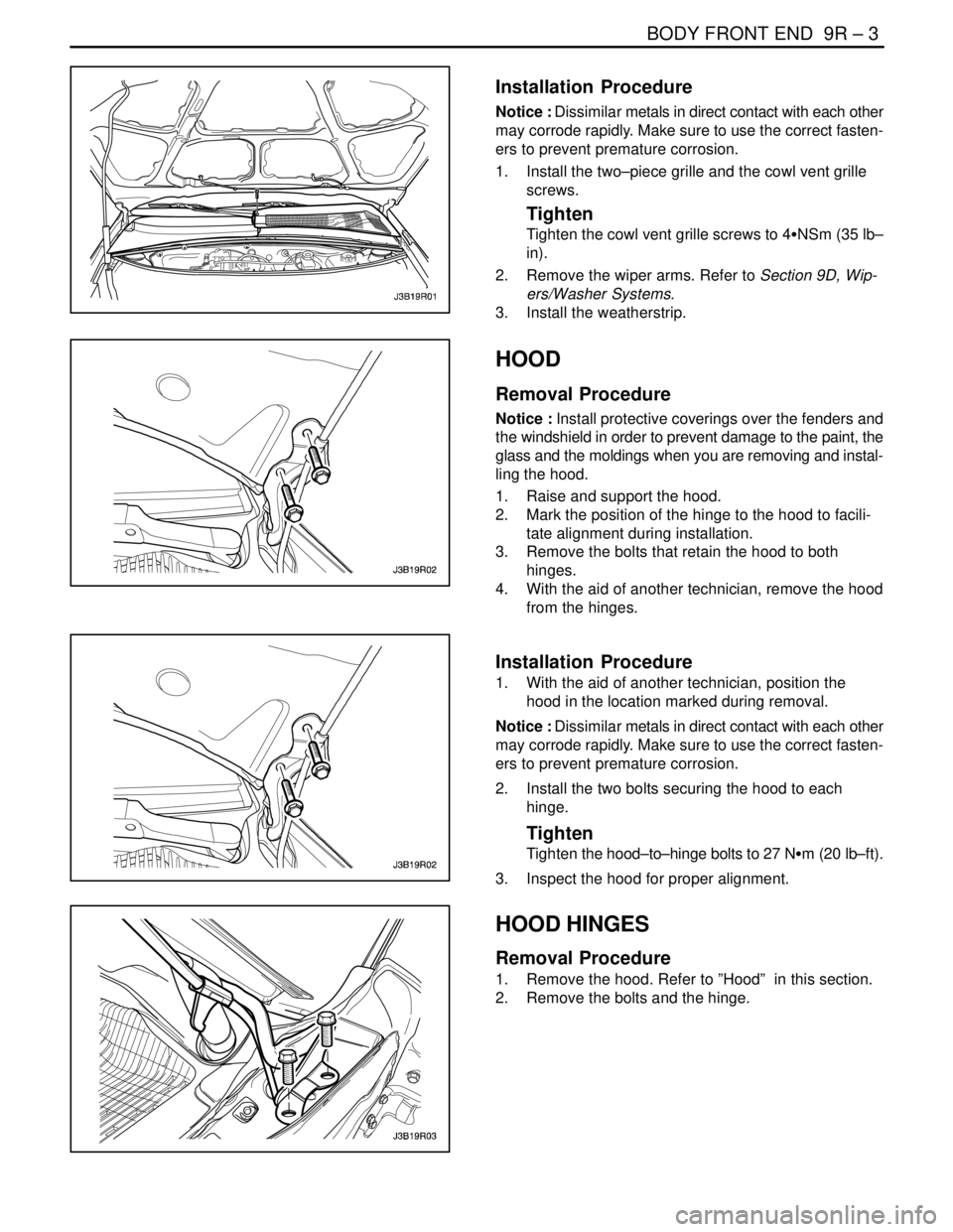
1. Raise and support the hood.
2. Mark the position of the hinge to the hood to facili-
tate alignment during installation.
3. Remove the bolts that retain the hood to both
hinges.
4. With the aid of another technician, remove the hood
from the hinges.
Installation Procedure
1. With the aid of another technician, position the
hood in the location marked during removal.
Notice : Dissimilar metals in direct contact with each other
may corrode rapidly. Make sure to use the correct fasten-
ers to prevent premature corrosion.
2. Install the two bolts securing the hood to each
hinge.
Tighten
Tighten the hood–to–hinge bolts to 27 NSm (20 lb–ft).
3. Inspect the hood for proper alignment.
HOOD HINGES
Removal Procedure
1. Remove the hood. Refer to ”Hood” in this section.
2. Remove the bolts and the hinge.
Page 2468 of 2643
BODY FRONT END 9R – 7
DAEWOO V–121 BL4
Installation Procedure
1. Install the screws and the front wheel well splash
shield.
Tighten
Tighten the front wheel well splash shield screws to
2 NSm (18 lb–in).
2. Install the front mud guard. Refer to Section 9M,
Exterior Trim.
3. Install the front wheel. Refer to Section 2E, Tires
and Wheels.
4. Lower the vehicle.
FENDER
Removal Procedure
1. Remove the front wheel well splash shield. Refer to
”Front Wheel Well Splash Shield” in this section.
2. Reposition the front headlamp.
3. Remove the bolts securing the front fascia to the
fender.
4. Reposition the front fascia.
5. Remove the fender bolts behind the front fascia.
6. Remove the bolts at the base of the fender.
7. Open the front door and remove the bolt at the
base of the A–pillar.