Page 2412 of 2643

SECTION : 9O
BUMPERS AND FASCIAS
CAUTION : Disconnect the negative battery cable before removing or installing any electrical unit or when a tool
or equipment could easily come in contact with exposed electrical terminals. Disconnecting this cable will help
prevent personal injury and damage to the vehicle. The ignition must also be in LOCK unless otherwise noted.
TABLE OF CONTENTS
SPECIFICATIONS9O–1 . . . . . . . . . . . . . . . . . . . . . . . . . .
Fastener Tightening Specifications 9O–1. . . . . . . . . . .
MAINTENANCE AND REPAIR9O–2 . . . . . . . . . . . . . . .
ON–VEHICLE SERVICE 9O–2. . . . . . . . . . . . . . . . . . . . .
Front Bumper Fascia 9O–2. . . . . . . . . . . . . . . . . . . . . . .
Front Bumper Energy Absorber 9O–3. . . . . . . . . . . . . . Front Bumper Impact Bar 9O–4. . . . . . . . . . . . . . . . . . .
Notchback Rear Bumper Fascia 9O–4. . . . . . . . . . . . .
Hatchback Rear Bumper Fascia 9O–6. . . . . . . . . . . . .
Rear Bumper Impact Bar 9O–7. . . . . . . . . . . . . . . . . . .
GENERAL DESCRIPTION AND SYSTEM
OPERATION9O–9 . . . . . . . . . . . . . . . . . . . . . . . . . . . . . .
Bumpers 9O–9. . . . . . . . . . . . . . . . . . . . . . . . . . . . . . . . .
SPECIFICATIONS
FASTENER TIGHTENING SPECIFICATIONS
ApplicationNSmLb–FtLb–In
Fender–to–Fascia Bolts10–89
Fender–to–Fascia Screws2–18
Front Impact Bar Bolts3929–
Lower Fascia Screws2–18
Luggage Compartment Fascia Bolts10–89
Luggage Compartment Fascia Screws2–18
Rear Wheel Well Fascia Bolts2–18
Page 2414 of 2643
BUMPERS AND FASCIAS 9O – 3
DAEWOO V–121 BL4
Installation Procedure
1. Install the front bumper fascia.
Notice : Dissimilar metals in direct contact with each other
may corrode rapidly. Make sure to use the correct fasten-
ers to prevent premature corrosion.
2. Install the upper fascia screws.
3. Install the lower fascia clips.
4. Install the fender–to–fascia bolts and the screws.
Tighten
Tighten the fender–to–fascia bolts to 10 NSm (89 lb–
in).
Tighten the fender–to–fascia screws to 2 NSm (18 lb–
in).
5. Install the headlamps and the fog lamps. Refer to
Section 9B, Lighting Systems.
6. Install the front wheel well splash shields. Refer to
Section 9B, Lighting Systems.
7. Connect the negative battery cable.
FRONT BUMPER ENERGY
ABSORBER
Removal Procedure
1. Remove the front bumper fascia. Refer to ”Front
Bumper Fascia” in this section.
2. Remove the energy absorber.
Page 2415 of 2643

9O – 4IBUMPERS AND FASCIAS
DAEWOO V–121 BL4
Installation Procedure
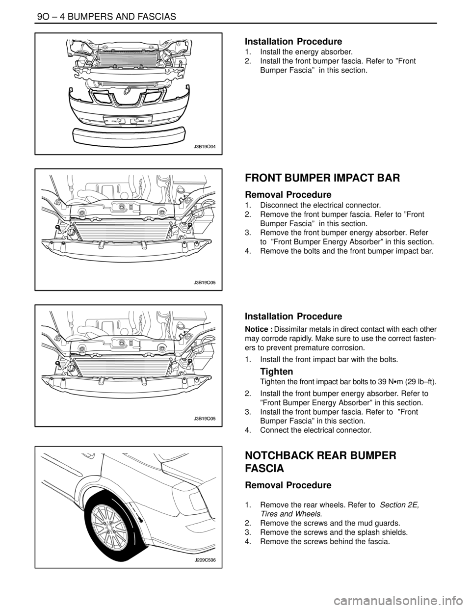
1. Install the energy absorber.
2. Install the front bumper fascia. Refer to ”Front
Bumper Fascia” in this section.
FRONT BUMPER IMPACT BAR
Removal Procedure
1. Disconnect the electrical connector.
2. Remove the front bumper fascia. Refer to ”Front
Bumper Fascia” in this section.
3. Remove the front bumper energy absorber. Refer
to ”Front Bumper Energy Absorber” in this section.
4. Remove the bolts and the front bumper impact bar.
Installation Procedure
Notice : Dissimilar metals in direct contact with each other
may corrode rapidly. Make sure to use the correct fasten-
ers to prevent premature corrosion.
1. Install the front impact bar with the bolts.
Tighten
Tighten the front impact bar bolts to 39 NSm (29 lb–ft).
2. Install the front bumper energy absorber. Refer to
”Front Bumper Energy Absorber” in this section.
3. Install the front bumper fascia. Refer to ”Front
Bumper Fascia” in this section.
4. Connect the electrical connector.
NOTCHBACK REAR BUMPER
FASCIA
Removal Procedure
1. Remove the rear wheels. Refer to Section 2E,
Tires and Wheels.
2. Remove the screws and the mud guards.
3. Remove the screws and the splash shields.
4. Remove the screws behind the fascia.
Page 2420 of 2643
BUMPERS AND FASCIAS 9O – 9
DAEWOO V–121 BL4
GENERAL DESCRIPTION
AND SYSTEM OPERATION
BUMPERS
The bumper systems are designed to sustain a collision
into a fixed barrier at either 8 km/h (5 mph) or 4 km/h (2.5
mph) without damage. After absorbing the energy of a col-lision, the bumper systems restore themselves to their
original positions. The bumpers feature an internal foam
energy absorber and a polymer fascia cover.
Page 2528 of 2643

3–2 WELDING AND TOOLSNUBIRA/LACETTI
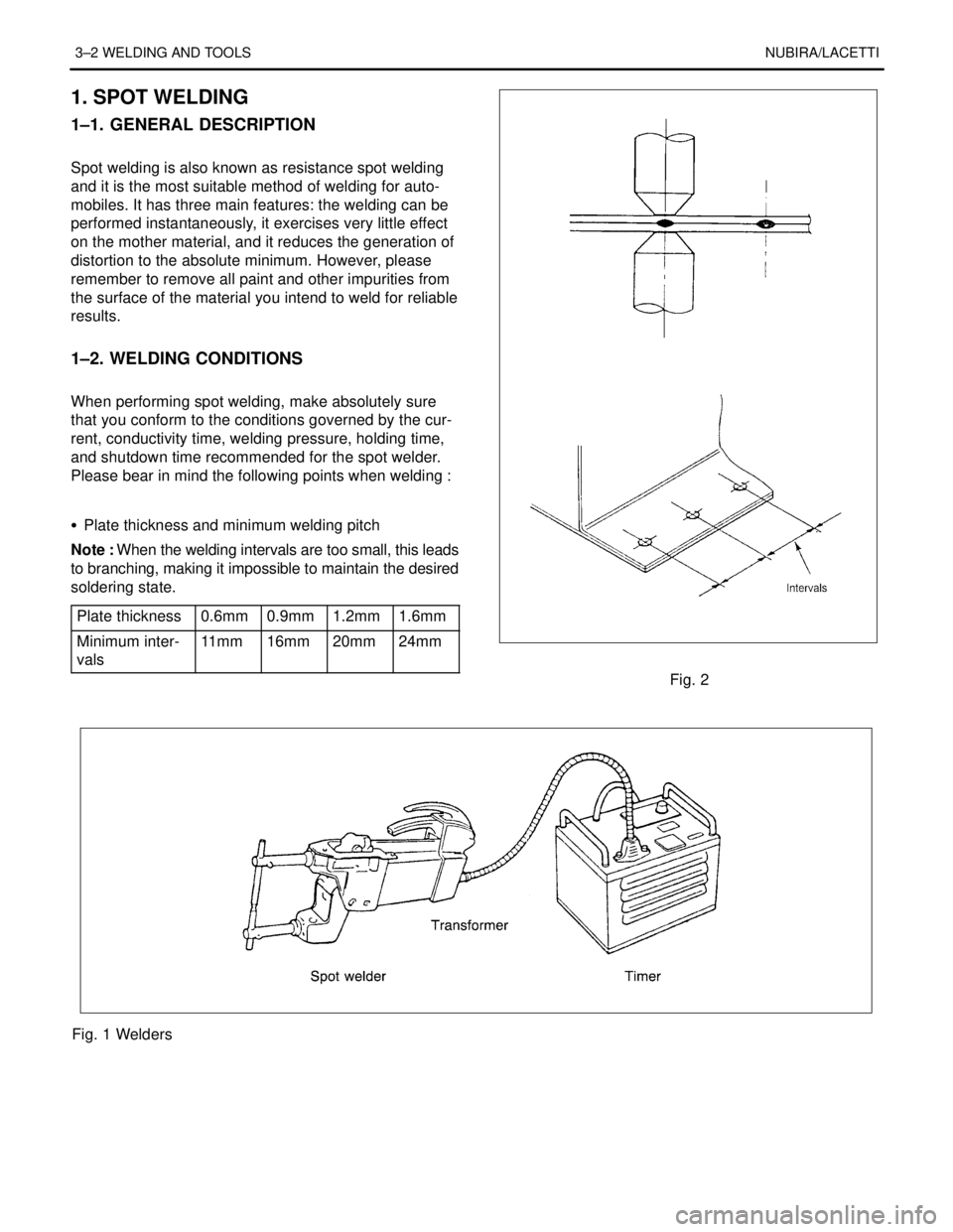
1. SPOT WELDING
1–1. GENERAL DESCRIPTION
.
Spot welding is also known as resistance spot welding
and it is the most suitable method of welding for auto-
mobiles. It has three main features: the welding can be
performed instantaneously, it exercises very little effect
on the mother material, and it reduces the generation of
distortion to the absolute minimum. However, please
remember to remove all paint and other impurities from
the surface of the material you intend to weld for reliable
results.
.
1–2. WELDING CONDITIONS
.
When performing spot welding, make absolutely sure
that you conform to the conditions governed by the cur-
rent, conductivity time, welding pressure, holding time,
and shutdown time recommended for the spot welder.
Please bear in mind the following points when welding :
.
S Plate thickness and minimum welding pitch
Note : When the welding intervals are too small, this leads
to branching, making it impossible to maintain the desired
soldering state.
Plate thickness
0.6mm0.9mm1.2mm1.6mm
Minimum inter-
vals11 m m16mm20mm24mm
Fig. 2
Fig. 1 Welders
Page 2540 of 2643
4–6 FRONTNUBIRA/LACETTI
2. FRONT WHEELHOUSE
2–1. GENERAL DESCRIPTION
The front wheelhouse component is constructed as a
unit with the locator shockabsorber. Therefore, replace-
ment of the component affects the front wheel align-ment. When assembling it, either use a jig or follow di-
mensions on the body repair chart for positioning. It
must be welded carefully.
Fig. 9 Front Wheelhouse Welding Assembly