2004 DAEWOO NUBIRA ABS
[x] Cancel search: ABSPage 1588 of 2643
ZF 4 HP 16 AUTOMATIC TRANSAXLE 5A1 – 239
DAEWOO V–121 BL4
S Excessive transaxle fluid leaking into the connector,
wicking up into the external wiring harness, and
degrading the wire insulation.
S Water/moisture intrusion in the connector.
S Low pin retention in the external connector from
excessive connection and disconnection of the wir-
ing connector assembly.
S Pin corrosion from contamination.
S Broken/cracked connector assembly.
S Points to remember when working with transaxle
wiring connector assembly.
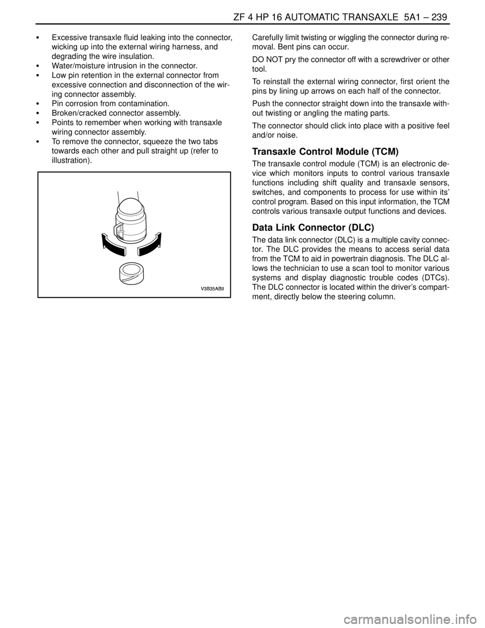
S To remove the connector, squeeze the two tabs
towards each other and pull straight up (refer to
illustration).Carefully limit twisting or wiggling the connector during re-
moval. Bent pins can occur.
DO NOT pry the connector off with a screwdriver or other
tool.
To reinstall the external wiring connector, first orient the
pins by lining up arrows on each half of the connector.
Push the connector straight down into the transaxle with-
out twisting or angling the mating parts.
The connector should click into place with a positive feel
and/or noise.
Transaxle Control Module (TCM)
The transaxle control module (TCM) is an electronic de-
vice which monitors inputs to control various transaxle
functions including shift quality and transaxle sensors,
switches, and components to process for use within its’
control program. Based on this input information, the TCM
controls various transaxle output functions and devices.
Data Link Connector (DLC)
The data link connector (DLC) is a multiple cavity connec-
tor. The DLC provides the means to access serial data
from the TCM to aid in powertrain diagnosis. The DLC al-
lows the technician to use a scan tool to monitor various
systems and display diagnostic trouble codes (DTCs).
The DLC connector is located within the driver’s compart-
ment, directly below the steering column.
Page 1962 of 2643
6E – 8ISTEERING WHEEL AND COLUMN
DAEWOO V–121 BL4
MAINTENANCE AND REPAIR
ON–VEHICLE SERVICE
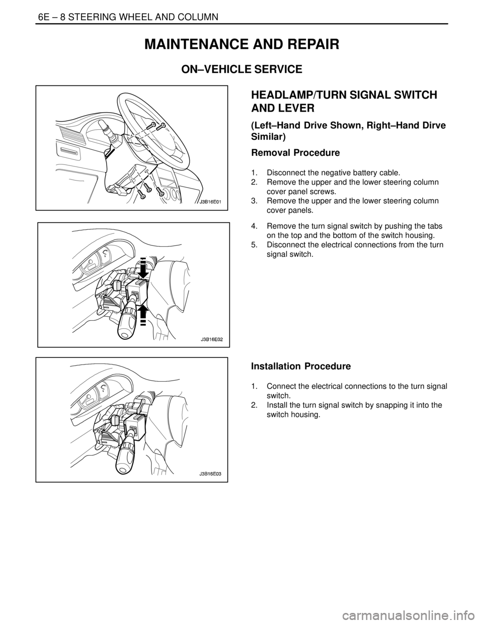
HEADLAMP/TURN SIGNAL SWITCH
AND LEVER
(Left–Hand Drive Shown, Right–Hand Dirve
Similar)
Removal Procedure
1. Disconnect the negative battery cable.
2. Remove the upper and the lower steering column
cover panel screws.
3. Remove the upper and the lower steering column
cover panels.
4. Remove the turn signal switch by pushing the tabs
on the top and the bottom of the switch housing.
5. Disconnect the electrical connections from the turn
signal switch.
Installation Procedure
1. Connect the electrical connections to the turn signal
switch.
2. Install the turn signal switch by snapping it into the
switch housing.
Page 1963 of 2643
STEERING WHEEL AND COLUMN 6E – 9
DAEWOO V–121 BL4
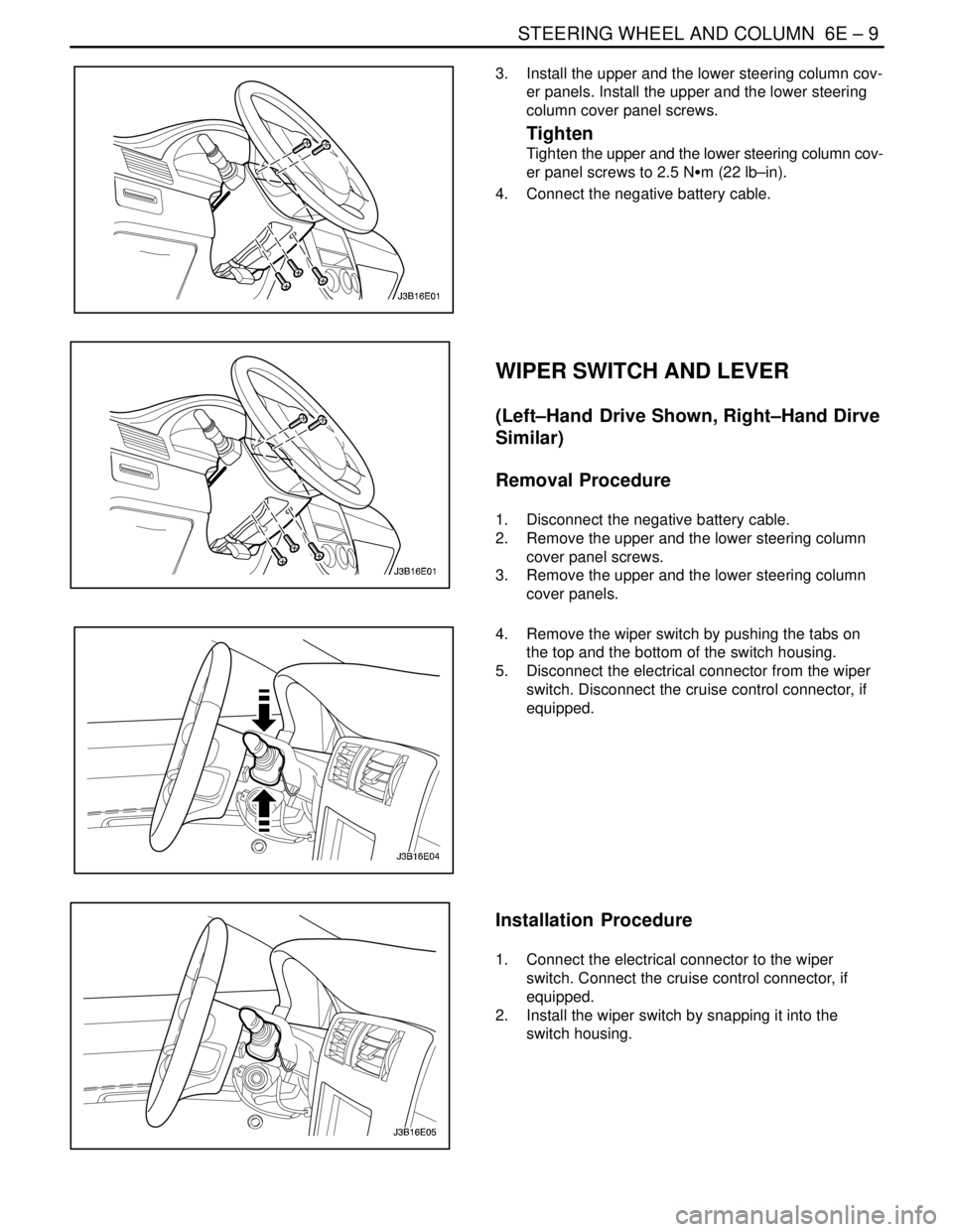
3. Install the upper and the lower steering column cov-
er panels. Install the upper and the lower steering
column cover panel screws.
Tighten
Tighten the upper and the lower steering column cov-
er panel screws to 2.5 NSm (22 lb–in).
4. Connect the negative battery cable.
WIPER SWITCH AND LEVER
(Left–Hand Drive Shown, Right–Hand Dirve
Similar)
Removal Procedure
1. Disconnect the negative battery cable.
2. Remove the upper and the lower steering column
cover panel screws.
3. Remove the upper and the lower steering column
cover panels.
4. Remove the wiper switch by pushing the tabs on
the top and the bottom of the switch housing.
5. Disconnect the electrical connector from the wiper
switch. Disconnect the cruise control connector, if
equipped.
Installation Procedure
1. Connect the electrical connector to the wiper
switch. Connect the cruise control connector, if
equipped.
2. Install the wiper switch by snapping it into the
switch housing.
Page 1966 of 2643
6E – 12ISTEERING WHEEL AND COLUMN
DAEWOO V–121 BL4
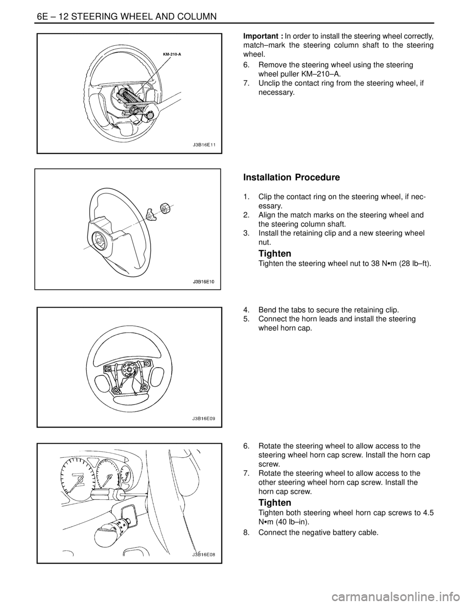
Important : In order to install the steering wheel correctly,
match–mark the steering column shaft to the steering
wheel.
6. Remove the steering wheel using the steering
wheel puller KM–210–A.
7. Unclip the contact ring from the steering wheel, if
necessary.
Installation Procedure
1. Clip the contact ring on the steering wheel, if nec-
essary.
2. Align the match marks on the steering wheel and
the steering column shaft.
3. Install the retaining clip and a new steering wheel
nut.
Tighten
Tighten the steering wheel nut to 38 NSm (28 lb–ft).
4. Bend the tabs to secure the retaining clip.
5. Connect the horn leads and install the steering
wheel horn cap.
6. Rotate the steering wheel to allow access to the
steering wheel horn cap screw. Install the horn cap
screw.
7. Rotate the steering wheel to allow access to the
other steering wheel horn cap screw. Install the
horn cap screw.
Tighten
Tighten both steering wheel horn cap screws to 4.5
NSm (40 lb–in).
8. Connect the negative battery cable.
Page 1967 of 2643
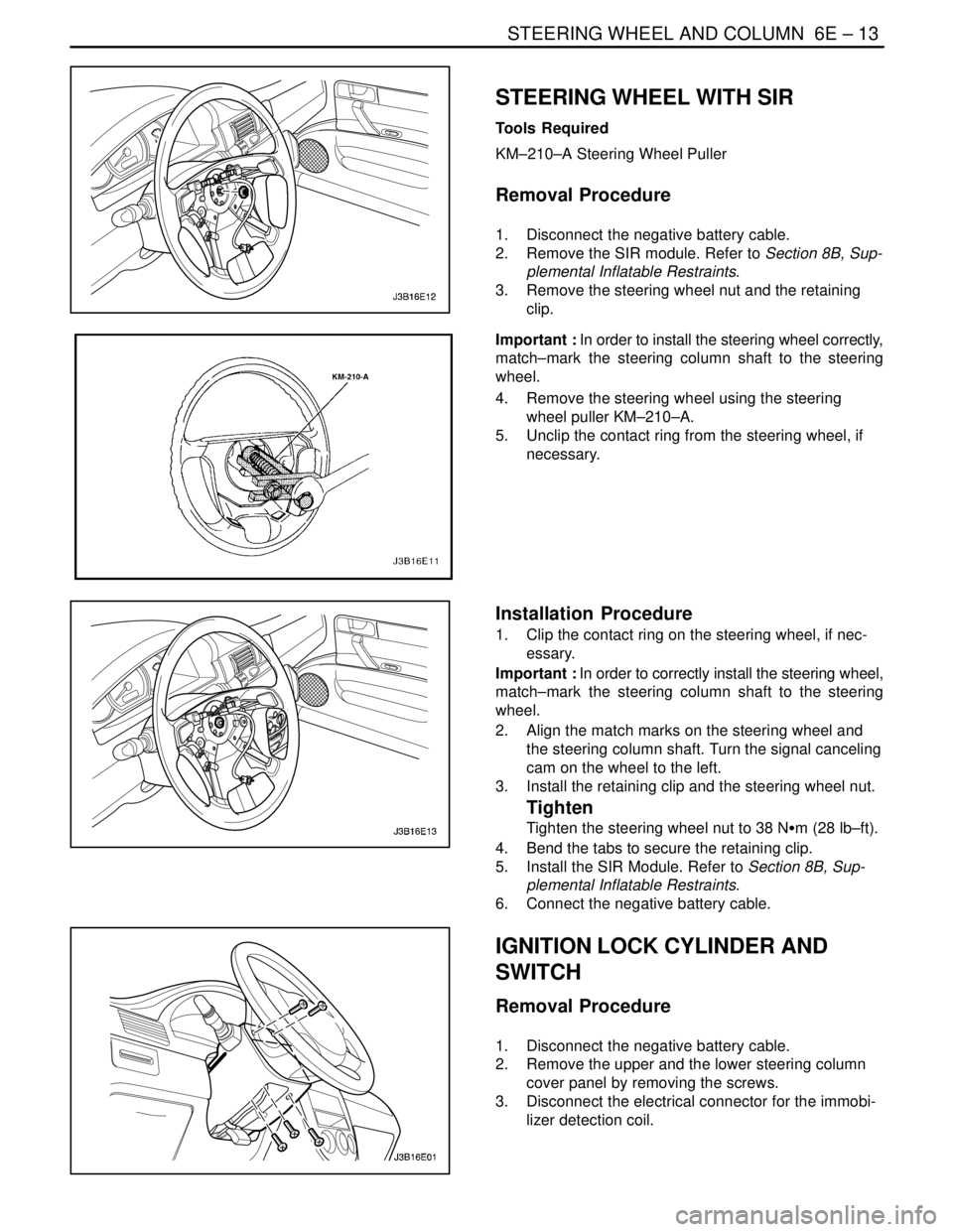
STEERING WHEEL AND COLUMN 6E – 13
DAEWOO V–121 BL4
STEERING WHEEL WITH SIR
Tools Required
KM–210–A Steering Wheel Puller
Removal Procedure
1. Disconnect the negative battery cable.
2. Remove the SIR module. Refer to Section 8B, Sup-
plemental Inflatable Restraints.
3. Remove the steering wheel nut and the retaining
clip.
Important : In order to install the steering wheel correctly,
match–mark the steering column shaft to the steering
wheel.
4. Remove the steering wheel using the steering
wheel puller KM–210–A.
5. Unclip the contact ring from the steering wheel, if
necessary.
Installation Procedure
1. Clip the contact ring on the steering wheel, if nec-
essary.
Important : In order to correctly install the steering wheel,
match–mark the steering column shaft to the steering
wheel.
2. Align the match marks on the steering wheel and
the steering column shaft. Turn the signal canceling
cam on the wheel to the left.
3. Install the retaining clip and the steering wheel nut.
Tighten
Tighten the steering wheel nut to 38 NSm (28 lb–ft).
4. Bend the tabs to secure the retaining clip.
5. Install the SIR Module. Refer to Section 8B, Sup-
plemental Inflatable Restraints.
6. Connect the negative battery cable.
IGNITION LOCK CYLINDER AND
SWITCH
Removal Procedure
1. Disconnect the negative battery cable.
2. Remove the upper and the lower steering column
cover panel by removing the screws.
3. Disconnect the electrical connector for the immobi-
lizer detection coil.
Page 1974 of 2643

6E – 20ISTEERING WHEEL AND COLUMN
DAEWOO V–121 BL4
GENERAL DESCRIPTION
AND SYSTEM OPERATION
STEERING WHEEL AND COLUMN
CAUTION : To ensure the energy–absorbing action of
the steering column, it is important to use only the
specified screws, bolts, and nuts, tightened to the
specified torque.
In addition to the steering function, the steering column
provides safety and security.
The energy–absorbing column is designed to compress in
a front–end collision to lessen the chance of driver injury.
The ignition switch and the lock are mounted on the col-
umn, allowing the ignition and steering operations to be
locked to inhibit theft of the car.
The column levers trigger the turn signals, the headlight
beams, and the windshield washer and wipers.The tilt steering column uses telescopic function to allow
the steering wheel to tilt up and down in and out. This en-
ables the driver to adjust the steering wheel to a comfort-
able position.
Notice : Apply a thin coat of lithium grease to all friction
points when reassembling.
The column may be disassembled and reassembled easi-
ly.IGNITION KEY REMINDER
The ignition key reminder alerts the driver that the key is
still in the ignition when the driver attempts to exit the ve-
hicle.
An internal switch in the ignition lock cylinder supplies bat-
tery voltage to the reminder chime module when all of the
following conditions are true:
S The key is in the ignition switch.
S The ignition is OFF.
S The driver’s door is open.
For information on removal and installation of the reminder
chime module, refer to Section 9E, Instrumentation/Driver
Information.
Page 1990 of 2643

7A – 16IHEATING AND VENTILATION SYSTEM
DAEWOO V–121 BL4
BLOWER NOISE
StepActionValue(s)YesNo
1Verify the customer’s complaint.
Are the customer’s concerns verified?–Go to Step 2System OK
21. Sit inside the vehicle.
2. Close the doors and the windows.
3. Turn the ignition ON.
4. Start the engine.
5. Set the temperature to full cold.
6. Cycle through the blower speeds, the modes,
and the temperature settings in order to find
the noise.
Is the blower noise constant at high blower speeds
or certain modes, but absent at lower speeds or in
other modes?–Go to Step 11Go to Step 3
3Check for vibrations from the blower motor and fan
assembly at each blower speed by feeling the blower
motor housing.
Did you find excessive vibration?–Go to Step 6Go to Step 4
41. Remove the blower motor and the fan assem-
bly. Refer to ”Blower Motor” in this section.
2. Check for foreign material at the opening of the
blower inlet.
Do you find any foreign material at the blower inlet?–Go to Step 5Go to Step 6
5Remove all foreign material.
Is the repair complete?–System OKGo to Step 6
61. Examine the blower fan for wear spots,
cracked blades, a cracked hub, a loose fan re-
taining nut, or bad alignment.
2. Examine the blower case for wear spots.
Did you find any problem?–Go to Step 7Go to Step 9
7Repair as required.
Is the repair complete?–System OKGo to Step 8
8Replace the motor and the fan assembly.
Is the repair complete?–System OKGo to Step 9
9If the noise is a click/tick or whine, replace the motor.
Is the repair complete?–System OKGo to Step 10
10Reinstall the original motor.
Is the problem still present?–Go to Step 11System OK
111. Set the blower speed on maximum.
2. Check full–hot to full–cold temperature posi-
tions in the defrost, floor, and vent modes.
Is the noise present in the defrost mode only?–Go to Step 12Go to Step 13
121. Check the ducts for obstructions or foreign ma-
terials.
2. Remove any obstructions or foreign materials.
3. Check the floor/defroster door seals.
4. Repair or replace the components, as needed.
Is the repair complete?–System OK–
13Is the noise present in the floor mode only?–Go to Step 12Go to Step 14
14Is the noise present in the vent mode only?–Go to Step 15Go to Step 16
Page 2301 of 2643

9E – 2IINSTRUMENTATION/DRIVER INFORMATION
DAEWOO V–121 BL4
SPECIFICATIONS
FASTENER TIGHTENING SPECIFICATIONS
ApplicationNSmLb–FtLb–In
Air Deflector Screws2–18
Chime Module Screws4–35
Clock Screws2–18
Cupholder Screws2.5–22
Deposit Box Screws2.5–22
Driver Knee Bolster Bolts10–89
Floor Console Brace Bolts4–35
Floor Console Brace Nuts4–35
HVAC Controls Screws4–35
Instrument Cluster Screws4–35
Instrument Cluster Trim Panel Screws4–35
Instrument Panel End Bolts2015–
Instrument Panel End Screws4–35
Instrument Panel Nuts Above the Steering Column2015–
Instrument Panel Bolts Behind the HVAC Controls4–35
Steering Column Bracket Nut2216–
Steering Column Lower Trim Cover Screws2.5–22
Steering Column U–Clamp Nuts2216–
Steering Column Upper Trim Cover Screws3–27
INSTRUMENT CLUSTER INDICATOR LAMPS
SPECIFICATIONS
Indicator LampColorBulb
ABS WarningAmber14 v 1.4 W
Airbag WarningRed14 v 1.4 W
Battery Charge IndicatorRed14 v 1.4 W
Check EngineAmber14 v 1.4 W
Door Open WarningRed14 v 1.4 W
Engine OverheatRed14 v 1.4 W
Fasten Seat Belt WarningRed14 v 1.4 W
High Beam IndicatorBlue14 v 1.4 W
Low Fuel Level WarningAmber14 v 4 W
Oil Pressure WarningRed14 v 1.4 W
Parking Brake Indicator and Brake Fluid WarningRed14 v 1.4 W
Service Engine Soon WarningAmber14 v 1.4 W
Transaxle Power Mode IndicatorAmber14 v 1.4 W
Turn Signal IndicatorsGreen14 v 1.4 W