2004 DAEWOO NUBIRA engine e
[x] Cancel search: engine ePage 1829 of 2643

FIVE–SPEED MANUAL TRANSAXLE 5B – 5
DAEWOO V–121 BL4
DIAGNOSIS
ISOLATE NOISE
Identify the cause of any noise before attempting to repair
the clutch, the transaxle, or their related link–ages.
Symptoms of trouble with the clutch or the manual trans-
axle include:
S A great effort required to shift gears.
S The sound of gears clashing and grinding.
S Gear blockout.
Any of these conditions requires a careful analysis. Make
the following checks before disassembling the clutch or
the transaxle for repairs.
Road Travel Noise
Many noises that appear to come from the transaxle may
actually originate with other sources such as the:
S Tires.
S Road surfaces.
S Wheel bearings.
S Engine.
S Exhaust system.
These noises may vary according to the:
S Size of the vehicle.
S Type of the vehicle.
S Amount of insulation used in the body of the ve-
hicle.
Transaxle Noise
Transaxle gears, like any mechanical device, are not ab-
solutely quiet and will make some noise during normal op-
eration.
To verify suspected transaxle noises:
1. Select a smooth, level asphalt road to reduce tire
and resonant body noise.
2. Drive the vehicle far enough to warm up all the lu-
bricants thoroughly.
3. Record the speed and the gear range of the trans-
axle when the noise occurs.
4. Check for noises with the vehicle stopped, but with
the engine running.
5. Determine if the noise occurs while the vehicle op-
erates in:
S Drive – under a light acceleration or a heavy
pull.
S Float – maintaining a constant speed with a light
throttle on a level road.
S Coast – with the transaxle in gear and the
throttle partly or fully closed.
S All of the above.
Bearing Noise
Differential Side Bearing Noise
Differential side bearing noise and wheel bearing noise
can be confused easily. Since side bearings are pre–
loaded, a differential side bearing noise should not dimin-
ish much when the differential/transaxle is run with the
wheels off the ground.
Wheel Bearing Noise
Wheel bearings produce a rough growl or grating sound
that will continue when the vehicle is coasting and the
transaxle is in NEUTRAL. Since wheel bearings are not
pre–loaded, a wheel bearing noise should diminish con-
siderably when the wheels are off the ground.
Other Noise
Brinelling
A brinelled bearing causes a ”knock” or ”click” approxi-
mately every second revolution of the wheel because the
bearing rollers do not travel at the same speed as the
wheel. In operation, the effect is characterized by a low–
pitched noise.
A brinelled bearing is caused by excessive thrust which
pushes the balls up on the pathway and creates a triangu-
lar–shaped spot in the bearing race. A brinelled bearing
can also be caused from pressing one race into position
by applying pressure on the other race.
A false indication of a brinelled bearing occurs as a result
of vibration near the area where the bearing is mounted.
Brinelling is identified by slight indentations, resulting in a
washboard effect in the bearing race.
Lapping
Lapped bearing noise occurs when fine particles of abra-
sive materials such as scale, sand, or emery circulate
through the oil in the vehicle, causing the surfaces of the
roller and the race to wear away. Bearings that wear loose
but remain smooth, without spalling or pitting, are the re-
sult of dirty oil.
Locking
Large particles of foreign material wedged between the
roller and the race usually causes one of the races to turn,
creating noise from a locked bearing. Pre–loading regular
taper roller bearings to a value higher than that specified
also can result in locked bearings
Pitting
Pitting on the rolling surface comes from normal wear and
the introduction of foreign materials.
Spalling
Spalled bearings have flaked or pitted rollers or races
caused by an overload or an incorrect assembly that re-
sults in a misalignment, a cocking of bearings, or adjust-
ments that are too tight.
After completing these checks, refer to the ”Diagnosis
Chart” in this section.
Page 1830 of 2643

5B – 6IFIVE–SPEED MANUAL TRANSAXLE
DAEWOO V–121 BL4
SYMPTOM DIAGNOSIS
ChecksAction
Check for a knock at low speeds.S Replace any worn drive axle CV joints.
S Replace any worn side gear hub.
Check for a noise most pronounced on turns.S Correct any abnormalities in the differential gear.
Check for a clunk upon acceleration or deceleration.S Tighten any loose engine mounts.
S Replace any worn drive axle inboard joints.
S Replace any worn differential pinion shaft in the
case.
S Replace any worn side gear hub in the case.
Check for a clunking noise in turns.S Replace any worn outboard CV joint.
Check for a vibration.S Replace any rough wheel bearing.
S Replace any bent drive axle shaft.
S Replace any out–of–round tires.
S Balance any unbalanced tire.
S Replace any worn CV joint in the drive axle shaft.
S Correct an excessive drive axle angle by adjusting
the trim height.
Check for a noise in the NEUTRAL gear with the engine
running.S Replace any worn cluster bearing shaft.
S Replace any worn clutch–release bearing.
S Replace any worn input shaft cluster gears.
S Replace any worn first–gear/bearing.
S Replace any worn second–gear/bearing.
S Replace any worn third–gear/bearing.
S Replace any worn fourth–gear/bearing.
S Replace any worn fifth–gear/bearing.
S Replace any worn mainshaft bearings.
Check for a noise in the first gear (1) only.S Replace any chipped, scored, or worn first–gear
constant mesh gears.
S Replace any worn first–second gear synchronizer.
S Replace any worn first–gear/bearing.
S Replace any worn differential–gear/bearing.
S Replace any worn–ring gear.
S Adjust, repair, or replace the shift lever and the rods.
Check for a noise in the second gear (2) only.S Replace any chipped, scored, or worn second–gear
constant mesh gears.
S Replace any worn first–second gear synchronizer.
S Replace any worn second–gear/bearing.
S Replace any worn differential–gear/bearing.
S Replace any worn–ring gear.
S Adjust, repair, or replace the shift lever and the rods.
Check for a noise in the third gear (3) only.S Replace any chipped, scored, or worn third–gear
constant mesh gears.
S Replace any worn third–fourth gear synchronizer.
S Replace any worn third–gear/bearing.
S Replace any worn differential–gear/bearing.
S Replace any worn–ring gear.
S Adjust, repair, or replace the shift lever and the rods.
Page 1839 of 2643
FIVE–SPEED MANUAL TRANSAXLE 5B – 15
DAEWOO V–121 BL4
MAINTENANCE AND REPAIR
ON–VEHICLE SERVICE
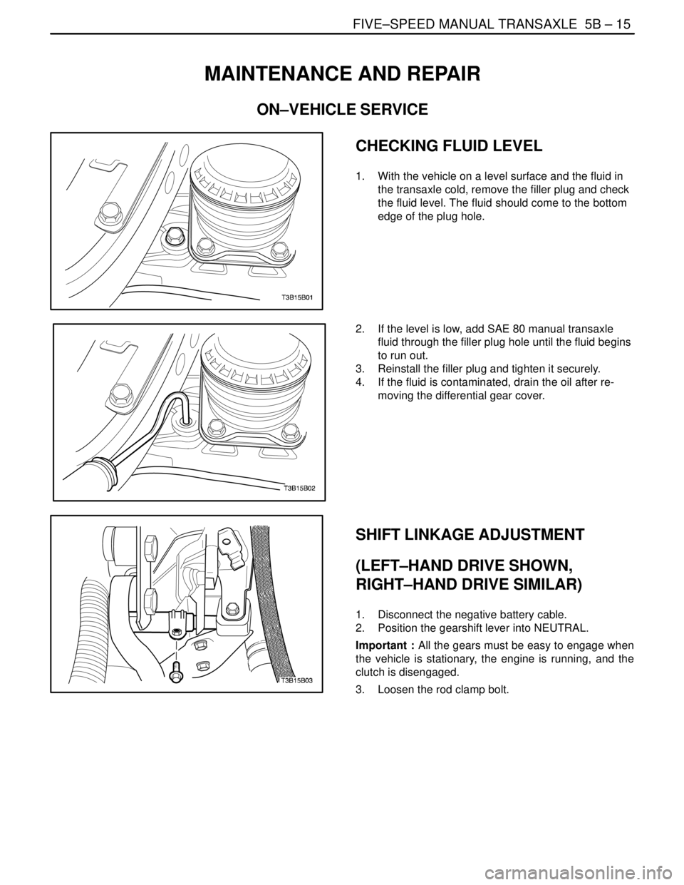
CHECKING FLUID LEVEL
1. With the vehicle on a level surface and the fluid in
the transaxle cold, remove the filler plug and check
the fluid level. The fluid should come to the bottom
edge of the plug hole.
2. If the level is low, add SAE 80 manual transaxle
fluid through the filler plug hole until the fluid begins
to run out.
3. Reinstall the filler plug and tighten it securely.
4. If the fluid is contaminated, drain the oil after re-
moving the differential gear cover.
SHIFT LINKAGE ADJUSTMENT
(LEFT–HAND DRIVE SHOWN,
RIGHT–HAND DRIVE SIMILAR)
1. Disconnect the negative battery cable.
2. Position the gearshift lever into NEUTRAL.
Important : All the gears must be easy to engage when
the vehicle is stationary, the engine is running, and the
clutch is disengaged.
3. Loosen the rod clamp bolt.
Page 1845 of 2643
FIVE–SPEED MANUAL TRANSAXLE 5B – 21
DAEWOO V–121 BL4
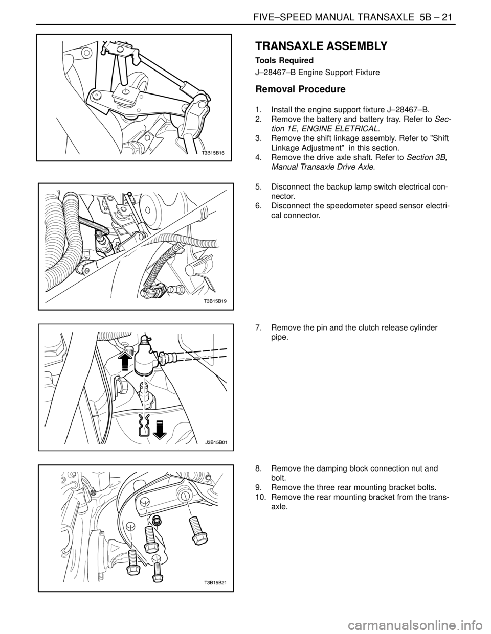
TRANSAXLE ASSEMBLY
Tools Required
J–28467–B Engine Support Fixture
Removal Procedure
1. Install the engine support fixture J–28467–B.
2. Remove the battery and battery tray. Refer to Sec-
tion 1E, ENGINE ELETRICAL.
3. Remove the shift linkage assembly. Refer to ”Shift
Linkage Adjustment” in this section.
4. Remove the drive axle shaft. Refer to Section 3B,
Manual Transaxle Drive Axle.
5. Disconnect the backup lamp switch electrical con-
nector.
6. Disconnect the speedometer speed sensor electri-
cal connector.
7. Remove the pin and the clutch release cylinder
pipe.
8. Remove the damping block connection nut and
bolt.
9. Remove the three rear mounting bracket bolts.
10. Remove the rear mounting bracket from the trans-
axle.
Page 1847 of 2643
FIVE–SPEED MANUAL TRANSAXLE 5B – 23
DAEWOO V–121 BL4
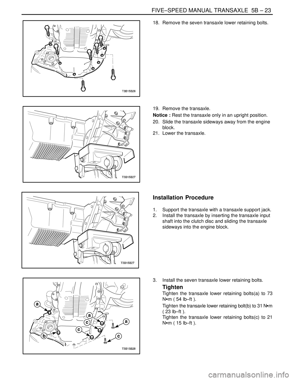
18. Remove the seven transaxle lower retaining bolts.
19. Remove the transaxle.
Notice : Rest the transaxle only in an upright position.
20. Slide the transaxle sideways away from the engine
block.
21. Lower the transaxle.
Installation Procedure
1. Support the transaxle with a transaxle support jack.
2. Install the transaxle by inserting the transaxle input
shaft into the clutch disc and sliding the transaxle
sideways into the engine block.
3. Install the seven transaxle lower retaining bolts.
Tighten
Tighten the transaxle lower retaining bolts(a) to 73
NSm ( 54 lb–ft ).
Tighten the transaxle lower retaining bolt(b) to 31 NSm
( 23 lb–ft ).
Tighten the transaxle lower retaining bolts(c) to 21
NSm ( 15 lb–ft ).
Page 1849 of 2643
FIVE–SPEED MANUAL TRANSAXLE 5B – 25
DAEWOO V–121 BL4
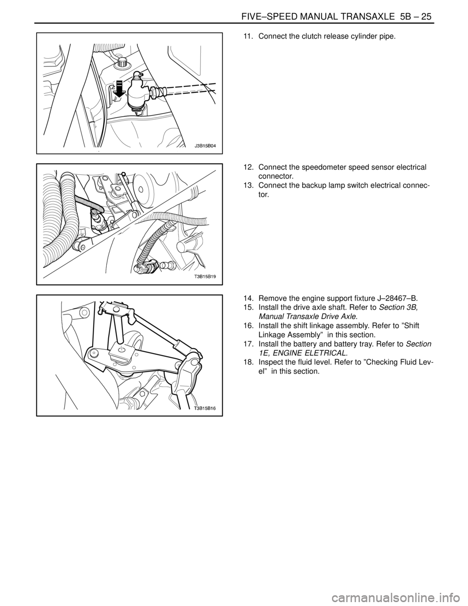
11. Connect the clutch release cylinder pipe.
12. Connect the speedometer speed sensor electrical
connector.
13. Connect the backup lamp switch electrical connec-
tor.
14. Remove the engine support fixture J–28467–B.
15. Install the drive axle shaft. Refer to Section 3B,
Manual Transaxle Drive Axle.
16. Install the shift linkage assembly. Refer to ”Shift
Linkage Assembly” in this section.
17. Install the battery and battery tray. Refer to Section
1E, ENGINE ELETRICAL.
18. Inspect the fluid level. Refer to ”Checking Fluid Lev-
el” in this section.
Page 1895 of 2643
5C – 8ICLUTCH
DAEWOO V–121 BL4
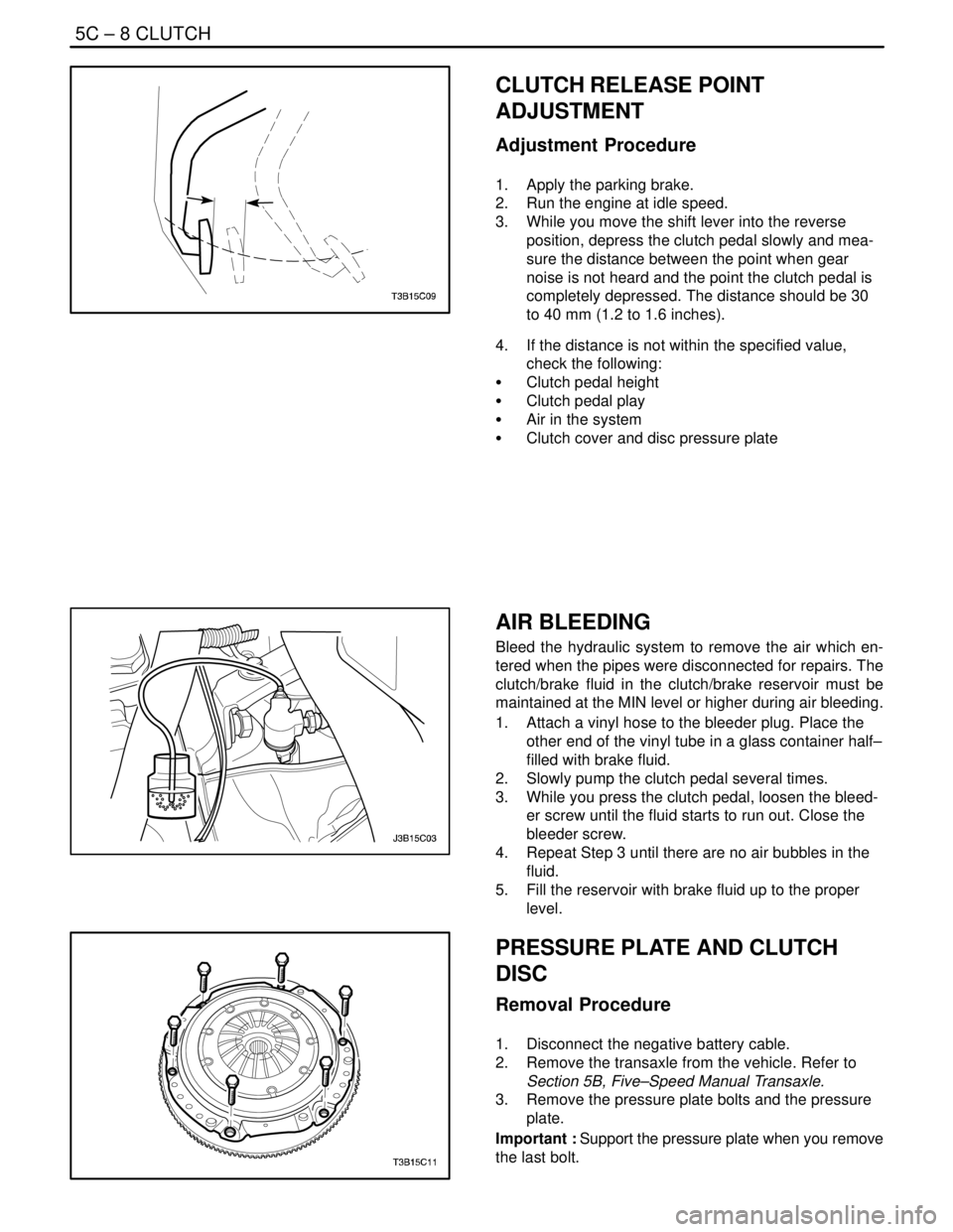
CLUTCH RELEASE POINT
ADJUSTMENT
Adjustment Procedure
1. Apply the parking brake.
2. Run the engine at idle speed.
3. While you move the shift lever into the reverse
position, depress the clutch pedal slowly and mea-
sure the distance between the point when gear
noise is not heard and the point the clutch pedal is
completely depressed. The distance should be 30
to 40 mm (1.2 to 1.6 inches).
4. If the distance is not within the specified value,
check the following:
S Clutch pedal height
S Clutch pedal play
S Air in the system
S Clutch cover and disc pressure plate
AIR BLEEDING
Bleed the hydraulic system to remove the air which en-
tered when the pipes were disconnected for repairs. The
clutch/brake fluid in the clutch/brake reservoir must be
maintained at the MIN level or higher during air bleeding.
1. Attach a vinyl hose to the bleeder plug. Place the
other end of the vinyl tube in a glass container half–
filled with brake fluid.
2. Slowly pump the clutch pedal several times.
3. While you press the clutch pedal, loosen the bleed-
er screw until the fluid starts to run out. Close the
bleeder screw.
4. Repeat Step 3 until there are no air bubbles in the
fluid.
5. Fill the reservoir with brake fluid up to the proper
level.
PRESSURE PLATE AND CLUTCH
DISC
Removal Procedure
1. Disconnect the negative battery cable.
2. Remove the transaxle from the vehicle. Refer to
Section 5B, Five–Speed Manual Transaxle.
3. Remove the pressure plate bolts and the pressure
plate.
Important : Support the pressure plate when you remove
the last bolt.
Page 1901 of 2643

5C – 14ICLUTCH
DAEWOO V–121 BL4
GENERAL DESCRIPTION
AND SYSTEM OPERATION
DRIVING MEMBERS
The driving members consist of two flat surfaces ma-
chined to a smooth finish. One of these is the rear face of
the engine flywheel and the other is the pressure plate.
The pressure plate is fitted into a steel cover which is
bolted the flywheel.
DRIVEN MEMBERS
The driven member is the clutch disc with a splined hub.The splined hub is free to slide lengthwise along the
splines of the input shaft and drives the input shaft through
these same splines.
The driving and driven members are held in contact by
spring pressure. This pressure is exerted by a diaphragm
spring in the pressure plate assembly.
OPERATING MEMBERS
The clutch release system consists of the clutch pedal, the
clutch master cylinder, and concentric slave cylinder.
Unlike the former system to release the clutch by the re-
lease lever and release fork, the concentric slave cylinder
type makes the concentric slave cylinder directly perform
the clutch release by the generated pressure through the
clutch pedal operation.