Page 1706 of 2643
5A2 – 116IAISIN AUTOMATIC TRANSAXLE
DAEWOO V–121 BL4
15. Connect the fluid cooler inlet and outlet pipe and
hose into the transaxle. Refer to ”Fluid Cooler Inlet
or Outlet Pipe and Hoses” in this section.
16. Install the left and right drive axle assemblies. Refer
to Section 3A, Automatic Transaxle Drive Axle.
17. Install the battery and battery tray. Refer to Section
1E, Engine Electrical.
18. Fill the transaxle with fluid. Refer to ”Fluid Drain
Procedure” in this section.
19. Check the fluid level. Refer to ”Transaxle Fluid Lev-
el Checking Procedure” in this section.
Page 1808 of 2643

5A2 – 218IAISIN AUTOMATIC TRANSAXLE
DAEWOO V–121 BL4
GENERAL DESCRIPTION
AND SYSTEM OPERATION
TRANSAXLE DESCRIPTION
The new automatic transmission is an electronically con-
trolled 4–speed automatic transmission with Lock–up
mechanism.
The transmission is mainly composed of the torque con-
verter with lock up clutch, newly developed 4–speed plan-
etary gear unit, the hydraulic control system and the elec-
tric control system.
ELECTRONICAL COMPONENTS
Transmission Control Module (TCM)
The TCM primarily controls shift points and lockup en-
gagement. It is located on the driver side under the instru-
ment panel.
The transmission is controlled by an electronic shift sys-
tem. The Transmission Control Module (TCM) processes
input signals. From the information received, the TCM
controls the transmission hydraulic system.
The electronic shift system consists of the following :
S Transmission control module (TCM)
S Shift solenoids (SS1 and SS2)
S Pressure control solenoid (PCS)
S Lockup solenoid
S Input shaft speed (ISS) sensor
S Output shaft speed (OSS) sensor
S Transmission Fluid Temperature (TFT) sensor
S Transmission Range (TR) Switch
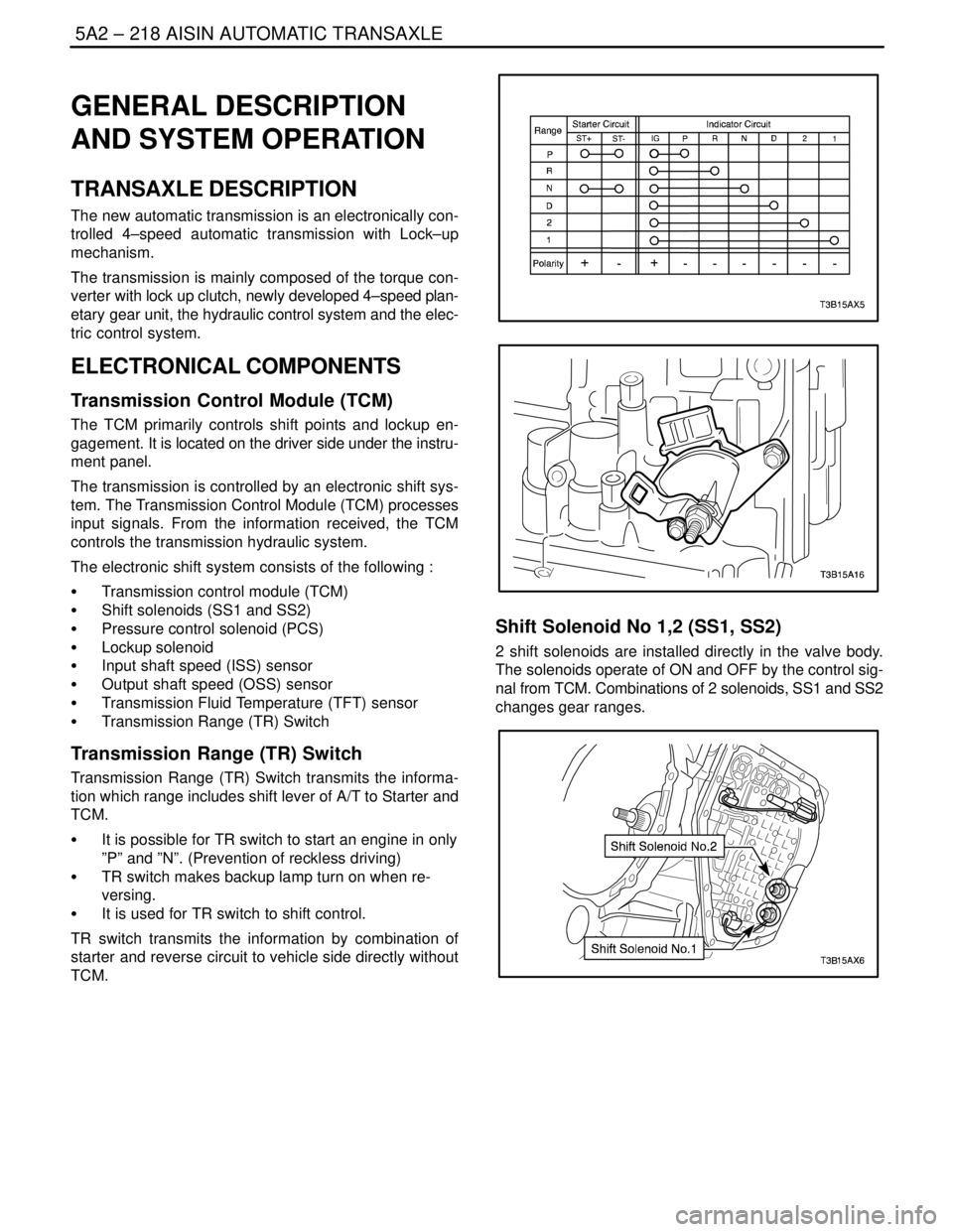
Transmission Range (TR) Switch
Transmission Range (TR) Switch transmits the informa-
tion which range includes shift lever of A/T to Starter and
TCM.
S It is possible for TR switch to start an engine in only
”P” and ”N”. (Prevention of reckless driving)
S TR switch makes backup lamp turn on when re-
versing.
S It is used for TR switch to shift control.
TR switch transmits the information by combination of
starter and reverse circuit to vehicle side directly without
TCM.
Shift Solenoid No 1,2 (SS1, SS2)
2 shift solenoids are installed directly in the valve body.
The solenoids operate of ON and OFF by the control sig-
nal from TCM. Combinations of 2 solenoids, SS1 and SS2
changes gear ranges.
Page 1816 of 2643
5A2 – 226IAISIN AUTOMATIC TRANSAXLE
DAEWOO V–121 BL4
6. Ring gear rotates clockwise.
7. Counter drive gear rotates clockwise for ring gear and one.
8. Counter drive gear rotates counterclockwise
9. Differential gear drive pinion rotates counterclockwise for counter driven gear and one.
10. Differential gear rotates clockwise.
( Engine Brake)
1. Counter drive gear and Planetary ring gear rotates counterclockwise.
2. Planetary long pinion rotates itself counterclockwise.
3. Planetary short pinion rotates itself clockwise.
4. Planetary carrier revolves clockwise due to rotation itself counterclockwise of planetary long pinion, but driving
force loses due to free of 1 way clutch NO.2 (F2). Therefore Engine brake does not operate.
Page 1818 of 2643
5A2 – 228IAISIN AUTOMATIC TRANSAXLE
DAEWOO V–121 BL4
6. Planetary carrier revolves clockwise due to reaction force of planetary long pinion.
7. Ring gear rotates clockwise.
8. Counter drive gear rotates clockwise for ring gear and one.
9. Counter driven gear rotates counterclockwise
10. Differential gear drive pinion rotates counterclockwise for counter driven gear and one.
11. Differential gear rotates clockwise.
( Engine Brake)
1. Counter drive gear and planetary ring gear rotates counterclockwise.
2. Planetary long pinion rotates itself counterclockwise.
3. Planetary short pinion rotates itself clockwise.
4. Rear sun gear rotates clockwise due to rotation itself counterclockwise of planetary long pinion, but driving force
loses due to free of 1 way clutch No.1(F1). Therefore Engine Brake does not operate.
Page 1820 of 2643
5A2 – 230IAISIN AUTOMATIC TRANSAXLE
DAEWOO V–121 BL4
5. Differential drive pinion rotates counterclockwise for counter driven gear and one.
6. Differential rotates clockwise.
( Engine Brake)
Driving force is connected to input shaft directory without 1 way clutch.
Therefore Engine Brake operates.
Page 1822 of 2643
5A2 – 232IAISIN AUTOMATIC TRANSAXLE
DAEWOO V–121 BL4
8. Counter driven gear rotates counterclockwise.
9. Differential gear drive pinion rotates counterclockwise for counter driven gear and one.
10. Differential gear rotates clockwise.
( Engine Brake)
Driving force is connected to input shaft directory without 1 way clutch.
Therefore Engine Brake operates.
Page 1824 of 2643
5A2 – 234IAISIN AUTOMATIC TRANSAXLE
DAEWOO V–121 BL4
5. Counter drive gear rotates counterclockwise for ring gear and one.
6. Counter driven gear rotates clockwise.
7. Differential gear drive pinion rotates clockwise for counter driven gear and one.
8. Differential gear rotates counterclockwise.
(Engine Brake)
Driving force is connected to input shaft directory without 1 way clutch.
Therefore Engine Brake operates.
Page 1827 of 2643
FIVE–SPEED MANUAL TRANSAXLE 5B – 3
DAEWOO V–121 BL4
SPECIAL TOOLS
SPECIAL TOOLS TABLE
J–6125–B
Slide Hammer
J–22888–20–A
Bearing Puller with
J–22888–35
Puller Legs
J–22912–01
Universal Bearing
Puller
J–28467–B
Engine Support
Fixture
KM–553–A
Fifth–Gear Puller
J–36633
Snap Ring Retainer
KM–113–2
Base
KM–334
Installer Sleeve