Page 2289 of 2643
9D – 12IWIPERS/WASHER SYSTEMS
DAEWOO V–121 BL4
StepNo Yes Value(s) Action
131. Connect an ohmmeter between terminals A1
and A3 of the wiper switch.
2. Observe the ohmmeter when the rear wiper
switch is moved to the WIPE position.
Does the ohmmeter indicate the specified value?� 0 WGo to Step 14Go to Step 15
14Repair the open circuit between terminal A1 of the
wiper connector (WHT wire) and the rear wiper mo-
tor.
Is the repair complete?–System OK–
15Replace the wiper switch.
Is the repair complete?–System OK–
Page 2290 of 2643

WIPERS/WASHER SYSTEMS 9D – 13
DAEWOO V–121 BL4
REAR WINDOW WASHER SYSTEM (HATCHBACK)
StepActionValue(s)YesNo
1Check the washer fluid level.
Is there fluid in the washer reservoir?–Go to Step 3Go to Step 2
2Fill the washer reservoir.
Is the repair complete?–System OK–
3Verify that the hoses are not obstructed or leaking by
disconnecting the washer hose and blowing through
it toward the reservoir and also toward the nozzle.
Are the hoses obstructed or leaking?–Go to Step 4Go to Step 5
4Repair or replace the hoses.
Is the repair complete?–System OK–
5Check the function of the rear wiper.
Does the rear wiper function correctly?–Go to Step 7Go to Step 6
6Repair the rear wiper.
Is the rear wiper repair complete?–Go to Step 7–
71. Disconnect the electrical connector at the
washer pump.
2. Use an ohmmeter to check continuity between
the BLK wire of the washer pump connector
and ground.
Does the ohmmeter indicate the specified value?� 0 WGo to Step 9Go to Step 8
8Repair the open or the high–resistance ground con-
nection.
Is the repair complete?–System OK–
9Check the voltage at the washer pump connector
(LT RED wire) when the rear washer is turned ON.
Is the voltage equal to the specified value?11–14 vGo to Step 10Go to Step 11
10Replace the washer pump.
Is the repair complete?–System OK–
111. Disconnect the wiper switch.
2. Connect an ohmmeter between terminal 3 and
terminal A2 of the wiper switch.
3. Observe the ohmmeter when the switch is
moved to the rear WASH position.
Does the ohmmeter indicate the specified value?� 0 WGo to Step 12Go to Step 13
12Repair the open circuit between terminal A2 of the
wiper switch connector and the rear washer pump.
Is the repair complete?–System OK–
13Replace the wiper switch.
Is the repair complete?–System OK–
Page 2299 of 2643

9D – 22IWIPERS/WASHER SYSTEMS
DAEWOO V–121 BL4
GENERAL DESCRIPTION
AND SYSTEM OPERATION
WINDSHIELD WIPER SYSTEM
The windshield wiper system consists of a wiper motor, a
linkage, a wiper arm and a blade, and a wiper/washer
switch. The windshield wiper circuit incorporates a self–
parking device which consists of a worm gear and a cam
plate in order to keep the circuit engaged temporarily when
the switch is turned off. The wiper system is driven by a
permanent magnet–type motor. The windshield wiper mo-
tor is mounted on the dash panel and is directly connected
to the windshield wiper linkage.
The windshield wiper motor has two speeds, LO and HI,
and also has intermittent wiper capability. The wiper
switch is an integral part of the wiper/washer switch. Wind-
shield wiper operation is actuated through the lever on the
right side of the steering column.
WINDSHIELD WASHER SYSTEM
The windshield washer system is equipped with a washerfluid reservoir, a washer fluid pump, hoses, nozzles, and
a wiper/washer switch. The windshield washer reservoir
is mounted behind the front left wheel well splash shield.
Attached to the reservoir is a washer pump, which pumps
fluid through the hoses to the two nozzles mounted on the
hood. The washer switch is an integral part of the wiper/
washer switch. Windshield washer operation is actuated
through the lever on the right side of the steering column.
REAR WINDOW WIPER/WASHER
SYSTEM
The rear window wiper system consists of a wiper motor,
a wiper arm, and a blade. The rear window wiper motor is
located inside the hatchback/tailgate door and is directly
connected to the rear window wiper. The rear window
washer system is equipped with a separate washer fluid
pump and hose. The hatchback has a hatch–mounted
rear window washer nozzle and on the wagon, the washer
nozzle is incorporated into the rear wiper motor. The rear
window washer reservoir is mounted behind the front left
wheel well splash shield. Attached to the reservoir is a
washer pump, which pumps fluid through a hose to the
rear washer nozzle.
Page 2323 of 2643

9E – 24IINSTRUMENTATION/DRIVER INFORMATION
DAEWOO V–121 BL4
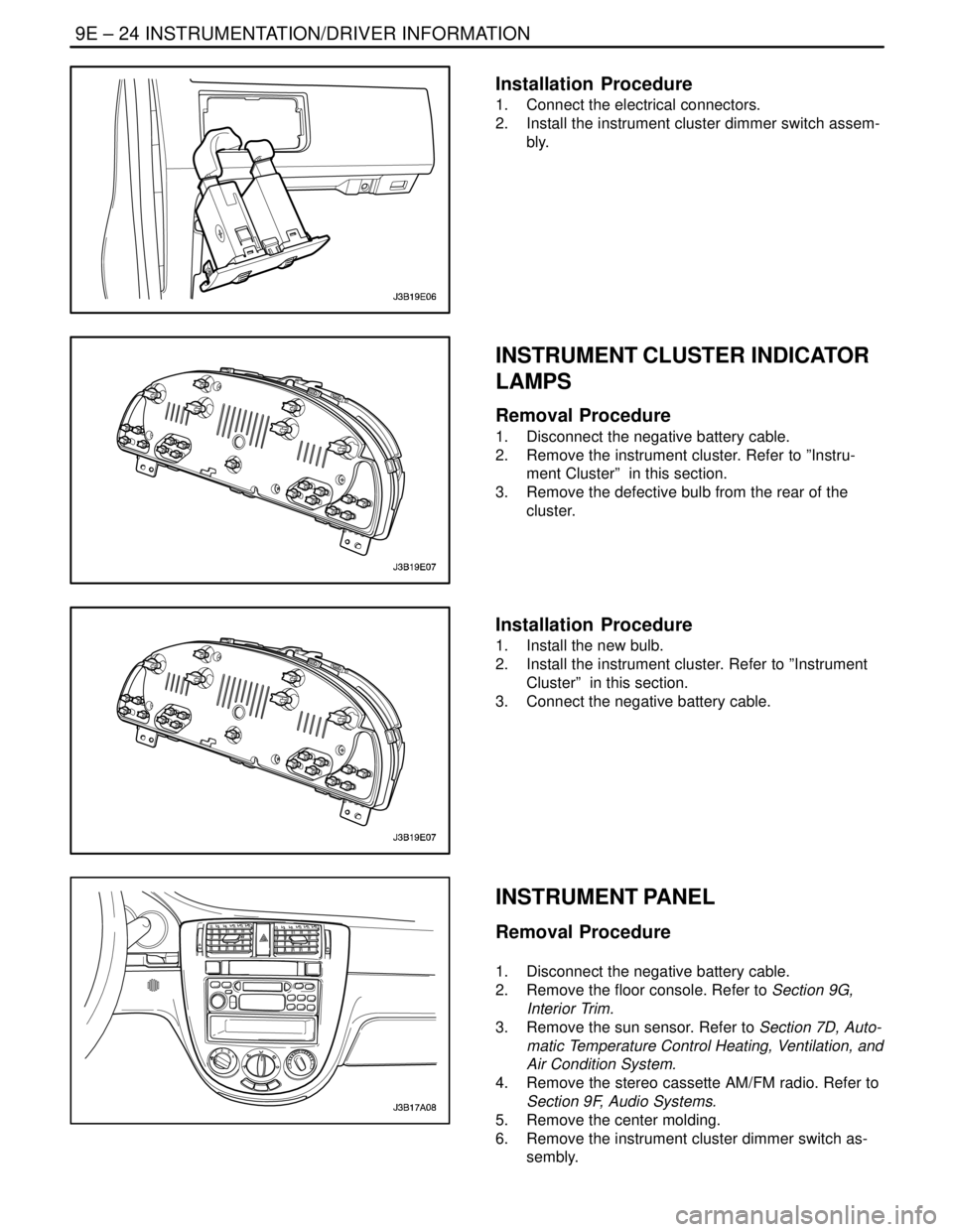
Installation Procedure
1. Connect the electrical connectors.
2. Install the instrument cluster dimmer switch assem-
bly.
INSTRUMENT CLUSTER INDICATOR
LAMPS
Removal Procedure
1. Disconnect the negative battery cable.
2. Remove the instrument cluster. Refer to ”Instru-
ment Cluster” in this section.
3. Remove the defective bulb from the rear of the
cluster.
Installation Procedure
1. Install the new bulb.
2. Install the instrument cluster. Refer to ”Instrument
Cluster” in this section.
3. Connect the negative battery cable.
INSTRUMENT PANEL
Removal Procedure
1. Disconnect the negative battery cable.
2. Remove the floor console. Refer to Section 9G,
Interior Trim.
3. Remove the sun sensor. Refer to Section 7D, Auto-
matic Temperature Control Heating, Ventilation, and
Air Condition System.
4. Remove the stereo cassette AM/FM radio. Refer to
Section 9F, Audio Systems.
5. Remove the center molding.
6. Remove the instrument cluster dimmer switch as-
sembly.
Page 2343 of 2643
INTERIOR TRIM 9G – 3
DAEWOO V–121 BL4
MAINTENANCE AND REPAIR
ON–VEHICLE SERVICE
FRONT DOOR TRIM PANEL
Tools Required
KM–475–B Trim Remover
Removal Procedure
1. Lower the front window.
2. Pry off the inside door handle trim bezel.
3. Remove the rear deck lid remote switch and the
power window/mirror control switch.
4. Disconnect the electrical connectors.
5. Remove the door trim panel screws.
6. Pry off the trim panel using the trim remover
KM–475–B.
Installation Procedure
1. Install the trim panel.
2. Connect the electrical connectors.
3. Install the rear deck lid remote switch and the pow-
er window/mirror control switch.
Page 2344 of 2643

9G – 4IINTERIOR TRIM
DAEWOO V–121 BL4
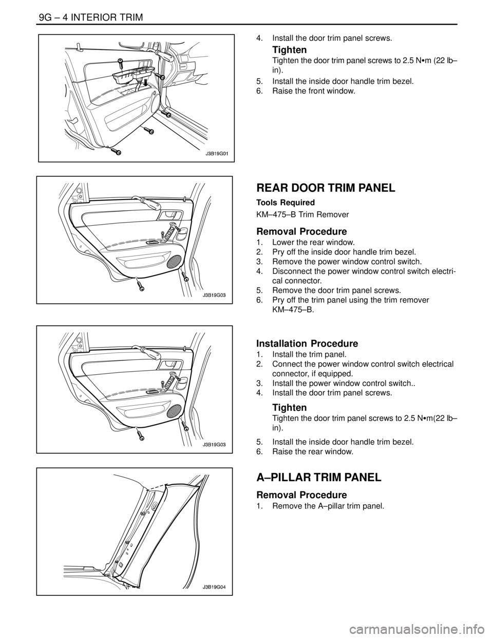
4. Install the door trim panel screws.
Tighten
Tighten the door trim panel screws to 2.5 NSm (22 lb–
in).
5. Install the inside door handle trim bezel.
6. Raise the front window.
REAR DOOR TRIM PANEL
Tools Required
KM–475–B Trim Remover
Removal Procedure
1. Lower the rear window.
2. Pry off the inside door handle trim bezel.
3. Remove the power window control switch.
4. Disconnect the power window control switch electri-
cal connector.
5. Remove the door trim panel screws.
6. Pry off the trim panel using the trim remover
KM–475–B.
Installation Procedure
1. Install the trim panel.
2. Connect the power window control switch electrical
connector, if equipped.
3. Install the power window control switch..
4. Install the door trim panel screws.
Tighten
Tighten the door trim panel screws to 2.5 NSm(22 lb–
in).
5. Install the inside door handle trim bezel.
6. Raise the rear window.
A–PILLAR TRIM PANEL
Removal Procedure
1. Remove the A–pillar trim panel.
Page 2385 of 2643

9L – 6IGLASS AND MIRRORS
DAEWOO V–121 BL4
StepNo Yes Value(s) Action
81. Turn the ignition OFF.
2. Disconnect the outside rearview mirror electri-
cal connector.
3. Use an ohmmeter to measure the resistance
between terminal 8 (BLK) of the outside rear-
view mirror connector and ground.
Does the ohmmeter indicate the specified value?� 0 ΩGo to Step 10 Go to Step 9
9Repair the open ground circuit for the outside rear-
view mirror.
Is the repair complete?–System OK–
10Replace the defective outside rearview mirror.
Is the repair complete?–System OK–
ELECTRIC CONTROL OUTSIDE REARVIEW MIRRORS
Electric Control Outside Rearview Mirrors Do Not Adjust
StepActionValue(s)YesNo
1Check fuse F8.
Is fuse F8 blown?–Go to Step 2 Go to Step 3
21. Check for a short circuit and repair it, if neces-
sary.
2. Replace fuse F8.
Is the repair complete?–System OK–
31. Turn the ignition ON.
2. Check the voltage at fuse F8.
Is the voltage at F8 equal to the specified value?11–14 vGo to Step 5 Go to Step 4
4Repair the open power supply circuit for fuse F8.
Is the repair complete?–System OK–
5Check the electric control outside rearview mirrors.
Are both electric control outside rearview mirrors in-
operative?–Go to Step 6 Go to Step 13
61. Remove the retaining screw for the electric
control outside rearview mirror and power win-
dow switch assembly.
2. Lift the switch assembly so that the connectors
on the underside are visible.
Is the connector secured to the electric control out-
side rearview mirror switch?–Go to Step 8 Go to Step 7
7Connect the connector to the electric control outside
rearview mirror switch.
Is the repair complete?–System OK–
8Use an ohmmeter to check the continuity between
terminal 6 (BLK) of the electric control outside rear-
view mirror switch connector and ground.
Does the ohmmeter indicate the specified value?� 0 ΩGo to Step 10 Go to Step 9
9Repair the open ground circuit for the electric control
outside rearview mirror switch.
Is the repair complete?–System OK–
Page 2386 of 2643

GLASS AND MIRRORS 9L – 7
DAEWOO V–121 BL4
StepNo Yes Value(s) Action
101. Turn the ignition ON.
2. Check the voltage at terminal 8 (BRN) of the
electric control outside rearview mirror switch
connector.
Is the voltage equal to the specified value?11–14 vGo to Step 12 Go to Step 11
11Repair the open power supply circuit for the electric
control outside rearview mirror switch.
Is the repair complete?–System OK–
12Replace the electric control outside rearview mirror
switch.
Is the repair complete?–System OK–
131. On the side which has the inoperative mirror,
remove the black plastic escutcheon from the
trim panel side of the door.
2. Disconnect the electric control outside rearview
mirror electrical connector.
3. Turn the ignition ON.
4. At the electric control outside rearview mirror
connector, connect a voltmeter between termi-
nal 4 (GRY) and terminal 6 (LT GRN if testing
the driver side or PPL/WHT if testing the pas-
senger side).
5. Operate the in/out adjustment on the switch,
and record the voltage indicated in each switch
position.
6. Connect a voltmeter between terminal 4 (GRY)
and terminal 7 (LT GRN if testing the left side
or RED/WHT if testing the right side).
7. Operate the up/down adjustment on the switch,
and record the voltage indicated in each switch
position.
Does the voltmeter indicate the specified voltage for
each test, with the polarity reversing when the switch
is changed from in to out or up to down?11–14 vGo to Step 14 Go to Step 15
14Replace the electric control outside rearview mirror.
Is the repair complete?–System OK–