2004 DAEWOO LACETTI window
[x] Cancel search: windowPage 2446 of 2643

9P – 26IDOORS
DAEWOO V–121 BL4
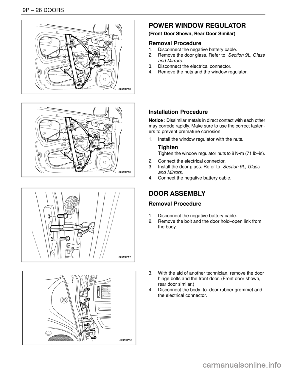
POWER WINDOW REGULATOR
(Front Door Shown, Rear Door Similar)
Removal Procedure
1. Disconnect the negative battery cable.
2. Remove the door glass. Refer to Section 9L, Glass
and Mirrors.
3. Disconnect the electrical connector.
4. Remove the nuts and the window regulator.
Installation Procedure
Notice : Dissimilar metals in direct contact with each other
may corrode rapidly. Make sure to use the correct fasten-
ers to prevent premature corrosion.
1. Install the window regulator with the nuts.
Tighten
Tighten the window regulator nuts to 8 NSm (71 lb–in).
2. Connect the electrical connector.
3. Install the door glass. Refer to Section 9L, Glass
and Mirrors.
4. Connect the negative battery cable.
DOOR ASSEMBLY
Removal Procedure
1. Disconnect the negative battery cable.
2. Remove the bolt and the door hold–open link from
the body.
3. With the aid of another technician, remove the door
hinge bolts and the front door. (Front door shown,
rear door similar.)
4. Disconnect the body–to–door rubber grommet and
the electrical connector.
Page 2449 of 2643

DOORS 9P – 29
DAEWOO V–121 BL4
GENERAL DESCRIPTION
AND SYSTEM OPERATION
DOOR LOCK STRIKER
The front and the rear door lock strikers each consist of a
striker with two screws threaded into a floating cage plate
in the B–pillars and the C–pillars. The door is secured in
the closed position when the door lock fork snaps over and
engages the striker.
CHILDPROOF REAR DOOR LOCK
The childproof rear door locks help prevent passengers,
especially children, from opening the rear doors of the ve-
hicle from the inside.
To activate the locks, move the levers of both rear doors
to the lock position. Then, close both doors. The rear pas-
sengers will be unable to open the doors from inside of the
vehicle.
To deactivate the locks, unlock the door from the inside of
the vehicle and open the door from the outside. Move the
lever to the unlock position. The rear door will now work
normally.
POWER DOOR LOCKS
The power door locks use a solenoid that is contained in
each door lock assembly. The door locks are activated by
the actuator on the inside door handle or by the lock cylin-
der on the driver’s side door only. When the driver’s side
door is locked or unlocked by the actuator or the lock cylin-
der, all doors are locked or unlocked accordingly.
POWER WINDOWS
The power windows are controlled by electrical switches
on the door panels and are operated by a motor at each
window regulator. Each door has a switch to control its
window, and the driver’s side door has four switches to
control all door windows on the vehicle. The windows are
lowered by pressing the switch and raised by pulling up on
the switch. The window will stop movement when the
switch is released or when the window is completely open
or closed.
The driver’s side window opens automatically. By pressing
and releasing the switch, the driver ’s side window will low-
er and will stop only when the switch is activated again, or
when the window is completely open.
The driver’s side door control also contains a window lock
button that will prevent the operation of the front passen-
ger door or the rear door windows when pressed.
Page 2489 of 2643

9T1 – 8IREMOTE KEYLESS ENTRY AND ANTI–THEFT SYSTEM
DAEWOO V–121 BL4
GENERAL DESCRIPTION
AND SYSTEM OPERATION
REMOTE KEYLESS ENTRY AND
ANTI–THEFT SYSTEM
The remote keyless entry and anti–theft system can per-
form the following functions:
S Remotely lock and unlock the vehicle doors by
means of a hand–held, high–frequency transmitter.
S Sense intrusion into the vehicle.
S Activate a warning in the event of an intrusion.
S Help the driver find the vehicle in a parking area.
S Automatically re–lock the doors if the door or the
trunk is not opened within 30 seconds after the ve-
hicle has been unlocked by the remote keyless
entry.
S Communicate serial data to a scan tool to help
diagnose system faults.
The remote keyless entry and anti–theft system consists
of the following components:
S Keyless entry and anti–theft control module/receiv-
er.
S Security indicator.
S Trunk open switch (NOTCHBACK).
S Trunk tamper switch (NOTCHBACK).
S Front door tamper switches.
S Door contact switches.
S Central door lock relay.
S Turn signal bulbs.
S Siren.
S Hood open switch.
REMOTE LOCKING AND UNLOCKING
The hand–held transmitter locks and unlocks the vehicle
doors by sending radio waves to the control module/re-
ceiver in the vehicle. The effective range of the transmitter
varies between 5 and 10 meters, (approximately 16 to 32
feet), depending on whether or not objects, such as other
vehicles are blocking the path of the radio waves.
The transmitter has a LOCK button and an UNLOCK but-
ton which only function when the ignition is OFF. Pressing
the UNLOCK button has the following effects:
S The doors are unlocked.
S The turn signal bulbs flash twice.
S The control module is disarmed.
Pressing the LOCK button has the following effects:
S The doors are locked.
S The turn signal bulbs flash once.
S The control module is armed.
The transmitter has a replaceable battery. The battery is
designed to last at least two years before replacement is
necessary.
SECURITY INDICATOR
There is a security indicator on the instrument panel. After
the LOCK button of the transmitter is pressed, the module
is placed in the armed mode, and the security indicator
flashes. The security indicator turns ON for 0.1 second
and OFF for 0.7 second. It then flashes at that frequency
until the control module/receiver is disarmed.
INTRUSION SENSING
The anti–theft function is armed if the transmitter sends
the LOCK message to the control module/receiver when
the ignition is OFF. When the hood, door, or trunk is
opened, the hood open, door contact, or trunk open switch
sends a ”ground” signal to the control module/receiver.
Unless the control module/receiver is disarmed, the siren
will be activated when the ”ground” signal is received from
the trunk open, hood open, or door contact switches.
The following actions disarm the anti–theft system:
S An UNLOCK message is received from the trans-
mitter.
S Key operation is detected by the tamper switches.
(The tamper switches are operated by the lock cyl-
inders in the front doors and trunk.)
The alarm will also be activated if the control module/re-
ceiver detects voltage from the ignition before either of the
following conditions occur:
S An UNLOCK message is received from the trans-
mitter.
S Key operation is indicated by the tamper switches.
SIREN (GENERAL ONLY)
The remote keyless entry system is armed when the
LOCK message is received from the transmitter when the
ignition is OFF. When the system is armed, it will activate
the siren and flash the turn signals for 28 seconds if any
of the following conditions occur:
S Close all the windows.
S Turn the ignition key to LOCK and remove the key.
S Have all passengers get out of the vehicle.
S Close all doors, the hood and the turnk lid.
S The control module/receiver detects ignition voltage
while the system is armed.
The siren will not operate if any of the following conditions
occur after the system has been armed:
S The door is opened with the key.
S The trunk is opened with the key.
S The UNLOCK or LOCK button on the remote trans-
mitter is pressed within 2 seconds after the siren is
activated.
VEHICLE LOCATOR
The remote keyless entry system assists the driver in lo-
cating the vehicle. When the vehicle is unlocked with the
remote control, the turn signals flash twice to indicate the
location of the vehicle. The duration of the flashes and the
Page 2511 of 2643

NUBIRA/LACETTIGENERAL INFORMATION 1–3
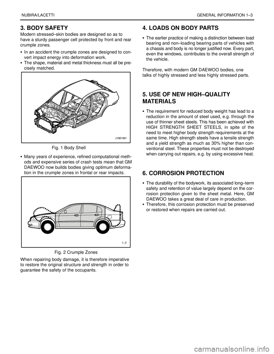
3. BODY SAFETY
Modern stressed–skin bodies are designed so as to
have a sturdy passenger cell protected by front and rear
crumple zones.
S In an accident the crumple zones are designed to con-
vert impact energy into deformation work.
S The shape, material and metal thickness must all be pre-
cisely matched.
Fig. 1 Body Shell
S Many years of experience, refined computational meth-
ods and expensive series of crash tests mean that GM
DAEWOO now builds bodies giving optimum deforma-
tion in the crumple zones in frontal or rear impacts.
Fig. 2 Crumple Zones
When repairing body damage, it is therefore imperative
to restore the original structure and strength in order to
guarantee the safety of the occupants.
4. LOADS ON BODY PARTS
S The earlier practice of making a distinction between load
bearing and non–loading bearing parts of vehicles with
a chassis and body is no longer justified now. Every part,
even the windows, contributes to the overall strength of
the vehicle.
.
Therefore, with modern GM DAEWOO bodies, one
talks of highly stressed and less highly stressed parts.
.
.
5. USE OF NEW HIGH–QUALITY
MATERIALS
S The requirement for reduced body weight has lead to a
reduction in the amount of steel used, e.g. through the
use of thinner sheet steels. This has been achieved with
HIGH STRENGTH SHEET STEELS, in spite of the
need to meet higher body strength requirements at the
same time. High strength steels have a tensile strength
and a yield strength as much as 30% higher than con-
ventional steel. These properties must not be destroyed
when carrying out repairs, e.g. by using excessive heat.
.
.
6. CORROSION PROTECTION
S The durability of the bodywork, its associated long–term
safety and retention of value largely depend on the cor-
rosion protection given to the sheet metal. Here, GM
DAEWOO takes a great deal of care in production.
S Therefore, this corrosion protection must be preserved
or restored when repairs are carried out.
Page 2571 of 2643

6–6 FRAME DOOR OPENING, DOOR AND SIDE PANEL OUTER NUBIRA/LACETTI
2. DOOR
2–1. REPAIR PROCEDURE
1. Remove the related parts.
S Door trim and related parts.
S Wiring harness and solenoid valve.
S Glass and window lifter.
S Linkage, lock set and handle.
S Others.
Note : Inspection and choose the usable parts.
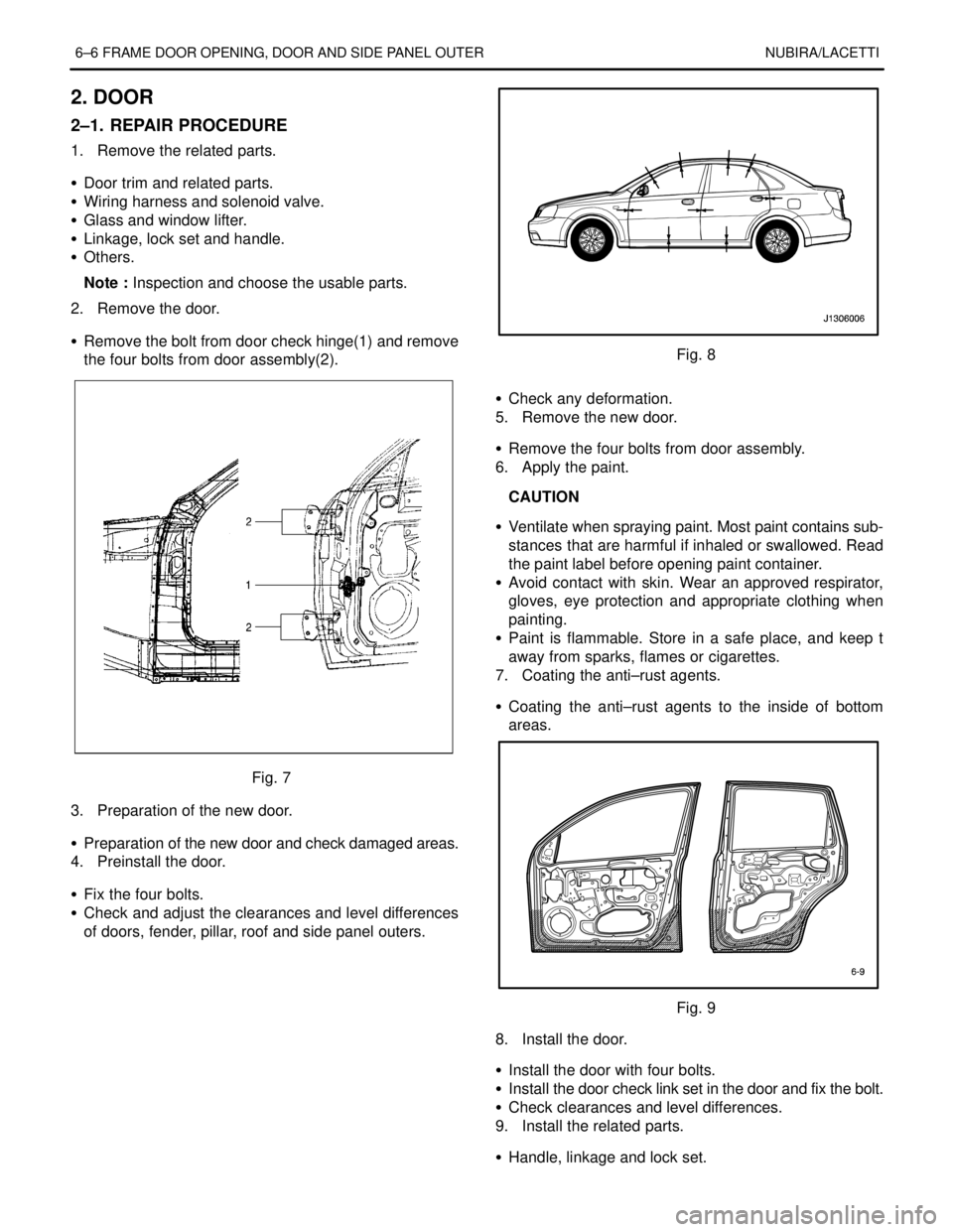
2. Remove the door.
S Remove the bolt from door check hinge(1) and remove
the four bolts from door assembly(2).
Fig. 7
3. Preparation of the new door.
S Preparation of the new door and check damaged areas.
4. Preinstall the door.
S Fix the four bolts.
S Check and adjust the clearances and level differences
of doors, fender, pillar, roof and side panel outers.
Fig. 8
S Check any deformation.
5. Remove the new door.
S Remove the four bolts from door assembly.
6. Apply the paint.
CAUTION
S Ventilate when spraying paint. Most paint contains sub-
stances that are harmful if inhaled or swallowed. Read
the paint label before opening paint container.
S Avoid contact with skin. Wear an approved respirator,
gloves, eye protection and appropriate clothing when
painting.
S Paint is flammable. Store in a safe place, and keep t
away from sparks, flames or cigarettes.
7. Coating the anti–rust agents.
S Coating the anti–rust agents to the inside of bottom
areas.
Fig. 9
8. Install the door.
S Install the door with four bolts.
S Install the door check link set in the door and fix the bolt.
S Check clearances and level differences.
9. Install the related parts.
S Handle, linkage and lock set.
Page 2572 of 2643

NUBIRA/LACETTI FRAME DOOR OPENING, DOOR AND SIDE PANEL OUTER 6–7
S Glass and window lifter.
S Solenoid valve and wiring harness.
S Install door trim and others.
Note : Before install the door trim and related parts, rub
in grease to the moving parts and check all operation.
10. Check and adjust.
S Check clearance and level differences.
S Check the door locking and unlocking condition.
S Check for water leaks in the passenger compartment.
S Install door trim and others.
Page 2581 of 2643

7–4 FENDER, HOOD, TAILGATE AND TRUNK LID NUBIRA/LACETTI
3. TAILGATE (HATCHBACK)
3–1. REPAIR PROCEDURE
1. Remove the related parts.
S Wiring harness.
S Rear wiper arm and motor.
S Rear window glass.
S Lock set, latch and others.
.
2. Remove the tailgate.
S Remove the tailgate mounting bolts from two hinge
bows.
Fig. 6
3. Preparation of the new tailgate.
S Preparation of the new tailgate and check damaged
areas.
.
4. Apply the paint.
CAUTION
S Ventilate when spraying paint. Most paint contains sub-
stances that are harmful if inhaled or swallowed.
S Avoid contact with skin. Wear an approved respirator,
gloves, eye protection and approriate clothing when
painting.
S Paint is flammable. Store in a safe place, and keep it
away from sparks, flames or cigarettes.
5. Preinstall the tailgate.
S Fasten to the tailgate hinges at two places with four
bolts, carefully.
S Install bumper.
S Close the tailgate and check the clearances and level
difference of tailgate, side panel outers and rear com-
bination lamps.Fig. 7
6. Tighten fully.
S After checking and adjusting the mounting position,
tighten all bolts fully.
.
7. Install the related parts.
S Wiring harness and solenoid valve.
S Lock set, latches and linkages.
S Install the rear window glass.
S Install in the reverse order in which they were removed.
.
8. Check and adjust.
S Clean the luggage compartment.
S Check clearances and level differences.
S Check the luggage locking and unlocking condition.
S Check for water leaks in the luggage compartment.
S Check the rear glass demist operation.