2004 DAEWOO LACETTI window
[x] Cancel search: windowPage 2297 of 2643

9D – 20IWIPERS/WASHER SYSTEMS
DAEWOO V–121 BL4
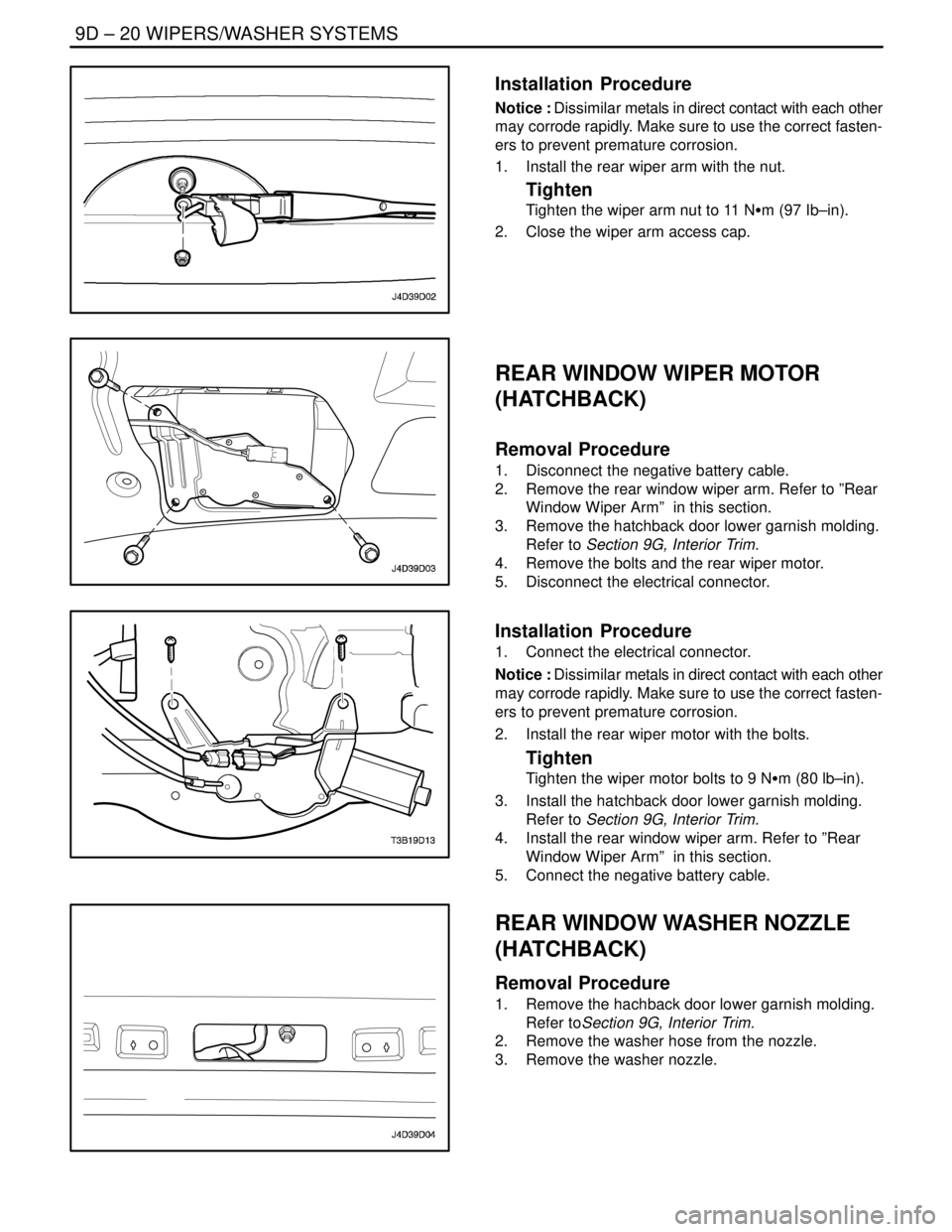
Installation Procedure
Notice : Dissimilar metals in direct contact with each other
may corrode rapidly. Make sure to use the correct fasten-
ers to prevent premature corrosion.
1. Install the rear wiper arm with the nut.
Tighten
Tighten the wiper arm nut to 11 NSm (97 Ib–in).
2. Close the wiper arm access cap.
REAR WINDOW WIPER MOTOR
(HATCHBACK)
Removal Procedure
1. Disconnect the negative battery cable.
2. Remove the rear window wiper arm. Refer to ”Rear
Window Wiper Arm” in this section.
3. Remove the hatchback door lower garnish molding.
Refer to Section 9G, Interior Trim.
4. Remove the bolts and the rear wiper motor.
5. Disconnect the electrical connector.
Installation Procedure
1. Connect the electrical connector.
Notice : Dissimilar metals in direct contact with each other
may corrode rapidly. Make sure to use the correct fasten-
ers to prevent premature corrosion.
2. Install the rear wiper motor with the bolts.
Tighten
Tighten the wiper motor bolts to 9 NSm (80 lb–in).
3. Install the hatchback door lower garnish molding.
Refer to Section 9G, Interior Trim.
4. Install the rear window wiper arm. Refer to ”Rear
Window Wiper Arm” in this section.
5. Connect the negative battery cable.
REAR WINDOW WASHER NOZZLE
(HATCHBACK)
Removal Procedure
1. Remove the hachback door lower garnish molding.
Refer toSection 9G, Interior Trim.
2. Remove the washer hose from the nozzle.
3. Remove the washer nozzle.
Page 2299 of 2643

9D – 22IWIPERS/WASHER SYSTEMS
DAEWOO V–121 BL4
GENERAL DESCRIPTION
AND SYSTEM OPERATION
WINDSHIELD WIPER SYSTEM
The windshield wiper system consists of a wiper motor, a
linkage, a wiper arm and a blade, and a wiper/washer
switch. The windshield wiper circuit incorporates a self–
parking device which consists of a worm gear and a cam
plate in order to keep the circuit engaged temporarily when
the switch is turned off. The wiper system is driven by a
permanent magnet–type motor. The windshield wiper mo-
tor is mounted on the dash panel and is directly connected
to the windshield wiper linkage.
The windshield wiper motor has two speeds, LO and HI,
and also has intermittent wiper capability. The wiper
switch is an integral part of the wiper/washer switch. Wind-
shield wiper operation is actuated through the lever on the
right side of the steering column.
WINDSHIELD WASHER SYSTEM
The windshield washer system is equipped with a washerfluid reservoir, a washer fluid pump, hoses, nozzles, and
a wiper/washer switch. The windshield washer reservoir
is mounted behind the front left wheel well splash shield.
Attached to the reservoir is a washer pump, which pumps
fluid through the hoses to the two nozzles mounted on the
hood. The washer switch is an integral part of the wiper/
washer switch. Windshield washer operation is actuated
through the lever on the right side of the steering column.
REAR WINDOW WIPER/WASHER
SYSTEM
The rear window wiper system consists of a wiper motor,
a wiper arm, and a blade. The rear window wiper motor is
located inside the hatchback/tailgate door and is directly
connected to the rear window wiper. The rear window
washer system is equipped with a separate washer fluid
pump and hose. The hatchback has a hatch–mounted
rear window washer nozzle and on the wagon, the washer
nozzle is incorporated into the rear wiper motor. The rear
window washer reservoir is mounted behind the front left
wheel well splash shield. Attached to the reservoir is a
washer pump, which pumps fluid through a hose to the
rear washer nozzle.
Page 2329 of 2643

9E – 30IINSTRUMENTATION/DRIVER INFORMATION
DAEWOO V–121 BL4
GENERAL DESCRIPTION
AND SYSTEM OPERATION
CIGAR LIGHTER
The cigar lighter is located in the front portion of the floor
console. To use the lighter, push it in completely. When the
lighter is hot, it will release itself from contact with the heat-
ing element. The lighter and the heating element can be
damaged if the lighter is not allowed to release itself fully
from the heating element.
ASHTRAY
The ashtray is located below the audio system. To access
the ashtray, pull it out from the center console. The ashtray
lamp will go on when the parking lamps or the headlamps
are turned on.
INSTRUMENT PANEL VENTS
The center and the side vents in the instrument panel can
be adjusted up and down and from side to side. The side
vents can also be aimed toward the side windows in order
to defog them.
GLOVE BOX
The glove box can be opened by pulling up on the latch
handle. The glove box must be removed in order to gain
access to the passenger’s side airbag module.
DIGTAL CLOCK
The digital clock is located in the instrument panel, above
the audio system. The clock is capable of a 12–hour or a
24–hour display.
INSTRUMENT CLUSTER
The instrument cluster is located above the steering col-
umn and in the instrument cluster trim panel. The instru-
ment cluster contains the instruments that provide the
driver with vehicle performance information. The instru-
ment cluster contains a speedometer, an odometer, a trip
odometer, a temperature gauge, a fuel gauge, and several
indicator lamps. For replacement of the indicator lamp
bulbs contained in the instrument cluster, refer to ”Instru-
ment Cluster Indicator Lamps Specifications” and”Instru-
ment Cluster Indicator Lamps” in this section.
SPEEDOMETER/ODOMETER/TRIP
ODOMETER
The speedometer measures the speed of the vehicle in
km/h (mph in some countries). It consists of an instrument
cluster gauge connected to the vehicle speed sensor
(VSS) on the transaxle output shaft.The odometer measures in kilometers (miles in some
countries) the total distance the vehicle has traveled since
it was manufactured. It consists of an instrument cluster
gauge connected to the VSS on the transaxle output shaft.
The trip odometer measures the distance the vehicle has
traveled since the odometer was last reset. It consists of
an instrument cluster gauge connected to the VSS on the
transaxle output shaft. The trip odometer can be reset to
zero at any time so that the driver can record the distance
traveled from any starting point.
FUEL GAUGE
The fuel gauge consists of an instrument cluster gauge
connected to a sending unit in the fuel tank.
The fuel gauge indicates the quantity of fuel in the tank
only when the ignition switch is turned to ON or ACC.
When the ignition is turned to LOCK or START, the pointer
may come to rest at any position.
TEMPERATURE GAUGE
The temperature gauge consists of an instrument cluster
gauge connected to a temperature sensor that is in con-
tact with the circulating engine coolant.
The temperature gauge indicates the temperature of the
coolant. Prolonged driving or idling in very hot weather
may cause the pointer to move beyond the center of the
gauge. The engine is overheating if the pointer moves into
the red zone at the upper limit of the gauge.
INSTRUMENT CLUSTER INDICATOR
LAMPS
The instrument cluster contains indicator lamps that indi-
cate the functioning of certain systems or the existence of
potential problems with the operation of the vehicle. The
indicator lamps are replaceable. For replacement of the in-
dicator lamps contained in the instrument cluster, refer to
”Instrument Cluster Indicator Lamps Specifications”
and”Instrument Cluster Indicator Lamps” in this section.
CHIME MODULE
The chime module is located above the instrument panel
fuse block and will sound in order to bring attention to one
or more of the following conditions:
S The lamps are on, the door is ajar, and the ignition
switch is not in ACC, ON, or START.
S The seat belt is unbuckled when the ignition switch
is in ON or START.
S The door is open when the ignition switch is in ON
or START.
S The key is left in the ignition switch when the igni-
tion is in LOCK and the door is open.
Page 2343 of 2643

INTERIOR TRIM 9G – 3
DAEWOO V–121 BL4
MAINTENANCE AND REPAIR
ON–VEHICLE SERVICE
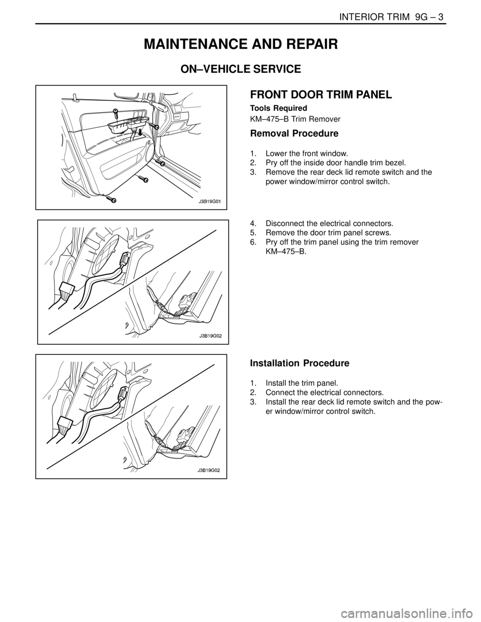
FRONT DOOR TRIM PANEL
Tools Required
KM–475–B Trim Remover
Removal Procedure
1. Lower the front window.
2. Pry off the inside door handle trim bezel.
3. Remove the rear deck lid remote switch and the
power window/mirror control switch.
4. Disconnect the electrical connectors.
5. Remove the door trim panel screws.
6. Pry off the trim panel using the trim remover
KM–475–B.
Installation Procedure
1. Install the trim panel.
2. Connect the electrical connectors.
3. Install the rear deck lid remote switch and the pow-
er window/mirror control switch.
Page 2344 of 2643

9G – 4IINTERIOR TRIM
DAEWOO V–121 BL4
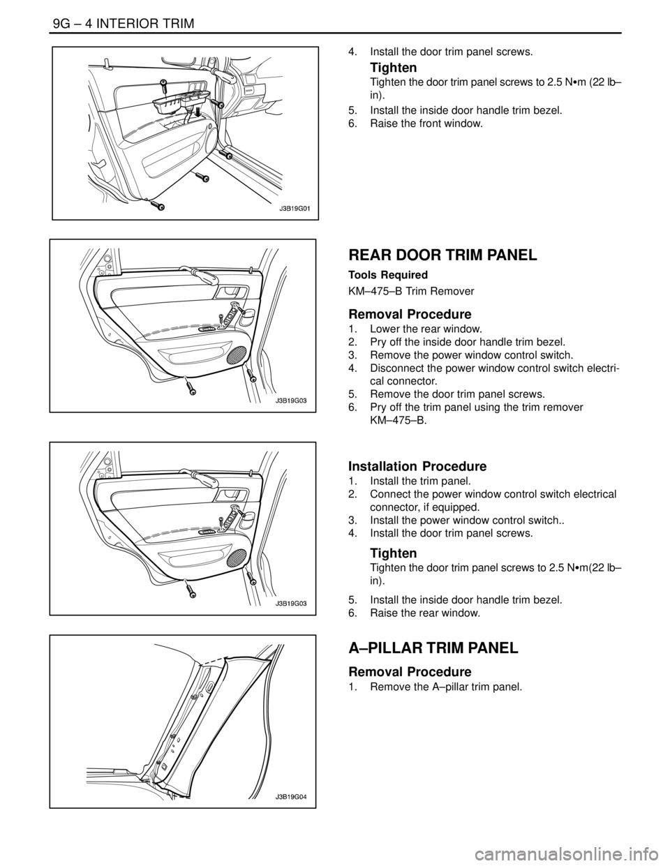
4. Install the door trim panel screws.
Tighten
Tighten the door trim panel screws to 2.5 NSm (22 lb–
in).
5. Install the inside door handle trim bezel.
6. Raise the front window.
REAR DOOR TRIM PANEL
Tools Required
KM–475–B Trim Remover
Removal Procedure
1. Lower the rear window.
2. Pry off the inside door handle trim bezel.
3. Remove the power window control switch.
4. Disconnect the power window control switch electri-
cal connector.
5. Remove the door trim panel screws.
6. Pry off the trim panel using the trim remover
KM–475–B.
Installation Procedure
1. Install the trim panel.
2. Connect the power window control switch electrical
connector, if equipped.
3. Install the power window control switch..
4. Install the door trim panel screws.
Tighten
Tighten the door trim panel screws to 2.5 NSm(22 lb–
in).
5. Install the inside door handle trim bezel.
6. Raise the rear window.
A–PILLAR TRIM PANEL
Removal Procedure
1. Remove the A–pillar trim panel.
Page 2356 of 2643

9G – 16IINTERIOR TRIM
DAEWOO V–121 BL4
GENERAL DESCRIPTION
AND SYSTEM OPERATION
INTERIOR TRIM PANELS
The interior trim panels are molded plastic and fasten with
screws or plastic clips.
PRESSURE RELIEF VENT
When all the windows are closed and the ventilation sys-
tem is on, the addition of outside air to the interior of the
vehicle causes a positive pressure within the vehicle. To
relieve the pressure, air is released through a pressure re-
lief vent. The pressure relief vents are located at the rear
quarter of the vehicle, behind the bumper fascia.
FLOOR CONSOLE
The floor console fits over the tunnel in the floor of the ve-
hicle and extends from under the center of the instrument
panel to the rear seat area. The front portion of the consolecontains the cigar lighter and the transaxle shift lever. The
rear portion of the console contains the parking brake le-
ver, a cupholder, a storage compartment, and an ashtray
for the rear seat occupants.
The sensing and diagnostic module (SDM) for the airbag
system and the remote keyless entry module are located
under the console.
FLOOR CARPET
The one–piece floor carpet goes over both the front and
the rear floor pans.
REAR COMPARTMENT SECURITY
COVER (HATCHBACK)
A rear compartment security cover is provided on the
hatchback model. The security cover is attached to the
hatch and can be easily removed if more cargo space is
needed.
Page 2369 of 2643

SECTION : 9I
WATERLEAKS
TABLE OF CONTENTS
SPECIFICATIONS9I–1 . . . . . . . . . . . . . . . . . . . . . . . . . . .
Recommended Materials for Waterleak Repairs 9I–1.
Watertest Stand Specifications 9I–1. . . . . . . . . . . . . . .
DIAGNOSIS9I–2 . . . . . . . . . . . . . . . . . . . . . . . . . . . . . . . . . Waterleak Diagnosis 9I–2. . . . . . . . . . . . . . . . . . . . . . . .
MAINTENANCE AND REPAIR9I–5 . . . . . . . . . . . . . . . .
ON–VEHICLE SERVICE 9I–5. . . . . . . . . . . . . . . . . . . . . .
Waterleak Repair 9I–5. . . . . . . . . . . . . . . . . . . . . . . . . . .
SPECIFICATIONS
RECOMMENDED MATERIALS FOR WATERLEAK
REPAIRS
Leak Areas Repair Materials
Windshield, back windowUrethane adhesive, caulking kit, or the equivalent
Metal jointsBrushable seam sealer which can be painted
Ventilation ducts3Mnv Auto Bedding and Glazing Compound or the equiva-
lent
Small cracks and pin holes3Mnv Drip–Check Sealer or the equivalent
Large holes3Mnv Automotive Joint and Seam Sealer
Weatherstrips3Mnv 08011 Weatherstrip Adhesive or the equivalent
Bolts, studs, and screwsStrip caulk
WATERTEST STAND SPECIFICATIONS
ApplicationDescription
Nozzle TypeFull jet spray nozzle #1/2 GG–25 or equivalent with a 60°
included angle
Nozzle HeightApproximately 1 600 mm (63.0 in.) from the floor
Volume of Flow14L (3.7 gal) per minute
Pressure155 kPa (22.5 psi) measured at the nozzle
Windshield and A–Pillar Test Stand PositionApproximately 30° down, 45° toward the rear, and aimed
at the corner of the windshield
B–Pillar Test Stand PositionApproximately 30° down, 45° toward the rear, and aimed
at the center of the rear door
Back Window and Rear Deck Lid Test Stand PositionApproximately 30° down, 30° toward the front and aimed
approximately 610 mm (24.0 in.) from the corner of the
back window
Page 2376 of 2643

9J – 2IWINDNOISE
DAEWOO V–121 BL4
MAINTENANCE AND REPAIR
ON–VEHICLE SERVICE
WINDNOISE REPAIR
Windnoise leak repairs are very similar to waterleak re-
pairs. Refer to Section 9I, Waterleaks. The actual proce-
dure depends on the type of seal being repaired.
Leaks around the door opening weatherstrips do not al-
ways indicate a faulty weatherstrip. A door or window ad-
justment may resolve the condition. Refer to Section 9P,
Doors or Section 9L, Glass and Mirrors.