2004 DAEWOO LACETTI Sensors
[x] Cancel search: SensorsPage 1485 of 2643

5A1 – 136IZF 4 HP 16 AUTOMATIC TRANSAXLE
DAEWOO V–121 BL4
DIAGNOSTIC TROUBLE CODE(DTC) P1672
CAN BUS OFF FAILURE
Circuit Description
The transaxle control module(TCM)is an electronic device
which monitors inputs to control various transaxle func-
tions including shift quality and transaxle sensors,
switches, and components to process for use within its’
control program. Based on this input information, the TCM
controls various transaxle output functions and devices.
Information is transmitted between the TCM and ECM
through the CAN. Information is as follows:
S Engine Malfunction Signal.
S Engine Speed.
S Engine Output Torque Reduction Signal.
S Engine Coolant Temperature.
Conditions for Setting the DTC
S System voltage is too high or too low.
S CAN transmitting wiring harness shortage or open.S TCM or ECM is defective.
S Immediately after the above condition occurs.
Action Taken When The DTC Sets
S The malfunction indicator lamp(MIL) will illuminate.
S The TCM will record operating conditions at the
time the diagnostic fails. This information will be
stored in the Failure Records buffer.
S Adopt Emergency/ Substitute mode and constant
4th gear by hydraulic control.
S After ignition OFF/ON : 3rd gear by hydraulic con-
trol. Possible P, R and N also possible.
Conditions for Clearing the MIL/DTC
S The MIL will turn OFF when the malfunction has
not occurred after three–ignition cycles.
S A history DTC will clear after 40 consecutive warm
up cycles without a fault.
S Using a scan tool can clear history DTCs.
Page 1487 of 2643

5A1 – 138IZF 4 HP 16 AUTOMATIC TRANSAXLE
DAEWOO V–121 BL4
DIAGNOSTIC TROUBLE CODE(DTC) P1673
CAN RECEIVE ECM MESSAGE FAILURE
Circuit Description
The transaxle control module(TCM) is an electronic de-
vice which monitors inputs to control various transaxle
functions including shift quality and transaxle sensors,
switches, and components to process for use within its’
control program. Based on this input information, the TCM
controls various transaxle output functions and devices.
Information is transmitted between the TCM and ECM
through the CAN. Information is as follows:
S Engine Malfunction Signal.
S Engine Speed.
S Engine Output Torque Reduction Signal.
S Engine Coolant Temperature.
Conditions for Setting the DTC
S System voltage is too high or too low.
S CAN transmitting wiring harness shortage or open.S TCM or ECM is defective.
S Immediately after the above condition occurs.
Action Taken When The DTC Sets
S The malfunction indicator lamp(MIL) will illuminate.
S The TCM will record operating conditions at the
time the diagnostic fails. This information will be
stored in the Failure Records buffer.
S Adopt Emergency/ Substitute mode and constant
4th gear by hydraulic control.
S After ignition OFF/ON : 3rd gear by hydraulic con-
trol. Possible P, R and N also possible.
Conditions for Clearing the MIL/DTC
S The MIL will turn OFF when the malfunction has
not occurred after three–ignition cycles.
S A history DTC will clear after 40 consecutive warm
up cycles without a fault.
S Using a scan tool can clear history DTCs.
Page 1581 of 2643

5A1 – 232IZF 4 HP 16 AUTOMATIC TRANSAXLE
DAEWOO V–121 BL4
GENERAL DESCRIPTION
AND SYSTEM OPERATION
The ZF 4HP 16 automatic transaxle consists primarily of
the following components.
Mechanical
S Torque converter with TCC
S Drive link assembly
S Two multiple disk clutch assemblies : Clutch B,E
S Three multiple brake assemblies : Brake C,D,F
S Lock–up clutch valve
S Two planetary gear sets
S One oil pump
S Final drive and differential assembly
Electronic
S Two shift solenoid valve(sol.1,2)
S Four pressure control solenoid valve(EDS)
S Two speed sensors : A/T ISS and A/T OSS
S Fluid temperature sensor
S Automatic transaxle control module(TCM)
S Wiring harness assembly
MECHANICAL COMPONENTS
Torque Converter
The converter consists of the impeller, the turbine wheel,
the reaction member (stator) and the oil to transmit torque.
The impeller, which is driven by the engine, causes the oil
in the converter to flow in a circular pattern. This oil flow
meets the turbine wheel, where is direction of flow is de-
flected. At the hub, the oil leaves the turbine and reaches
the reaction member (stator), where it is once again de-
flected so that it reaches the impeller at the correct angle
of flow.
The reversal effect generates movement in the stator, the
reaction torque then amplifies the turbine torque.
The ratio between turbine torque and torque is referred to
as torque multiplication.
The greater the difference is speed between the pump and
turbine, the greater the torque multiplication; it is at its
highest when the turbine is at a standstill. The higher the
speed of the turbine, the lower the torque multiplication.
When the turbine speed reaches about 85%of the pump
speed, torque multiplication=1, i.e. the turbine torque
equivalent to pump torque.
The stator, which bears against the housing via the free-
wheel, is then rotating freely in the oil flow and the free-
wheel is over–come. From this point onwards, the con-
verter acts as a straightforward fluid coupling.
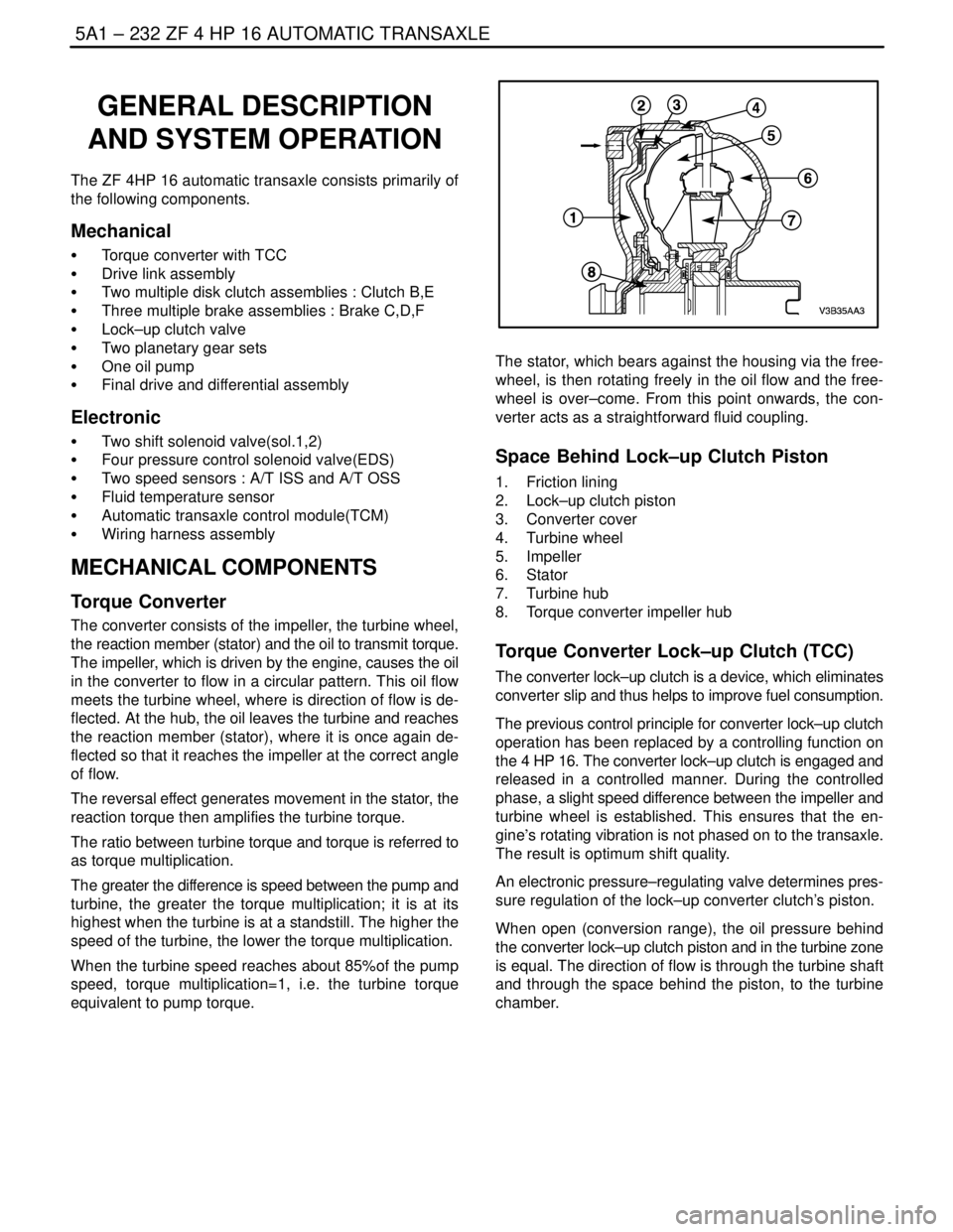
Space Behind Lock–up Clutch Piston
1. Friction lining
2. Lock–up clutch piston
3. Converter cover
4. Turbine wheel
5. Impeller
6. Stator
7. Turbine hub
8. Torque converter impeller hub
Torque Converter Lock–up Clutch (TCC)
The converter lock–up clutch is a device, which eliminates
converter slip and thus helps to improve fuel consumption.
The previous control principle for converter lock–up clutch
operation has been replaced by a controlling function on
the 4 HP 16. The converter lock–up clutch is engaged and
released in a controlled manner. During the controlled
phase, a slight speed difference between the impeller and
turbine wheel is established. This ensures that the en-
gine’s rotating vibration is not phased on to the transaxle.
The result is optimum shift quality.
An electronic pressure–regulating valve determines pres-
sure regulation of the lock–up converter clutch’s piston.
When open (conversion range), the oil pressure behind
the converter lock–up clutch piston and in the turbine zone
is equal. The direction of flow is through the turbine shaft
and through the space behind the piston, to the turbine
chamber.
Page 1588 of 2643

ZF 4 HP 16 AUTOMATIC TRANSAXLE 5A1 – 239
DAEWOO V–121 BL4
S Excessive transaxle fluid leaking into the connector,
wicking up into the external wiring harness, and
degrading the wire insulation.
S Water/moisture intrusion in the connector.
S Low pin retention in the external connector from
excessive connection and disconnection of the wir-
ing connector assembly.
S Pin corrosion from contamination.
S Broken/cracked connector assembly.
S Points to remember when working with transaxle
wiring connector assembly.
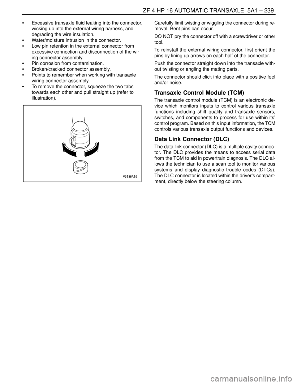
S To remove the connector, squeeze the two tabs
towards each other and pull straight up (refer to
illustration).Carefully limit twisting or wiggling the connector during re-
moval. Bent pins can occur.
DO NOT pry the connector off with a screwdriver or other
tool.
To reinstall the external wiring connector, first orient the
pins by lining up arrows on each half of the connector.
Push the connector straight down into the transaxle with-
out twisting or angling the mating parts.
The connector should click into place with a positive feel
and/or noise.
Transaxle Control Module (TCM)
The transaxle control module (TCM) is an electronic de-
vice which monitors inputs to control various transaxle
functions including shift quality and transaxle sensors,
switches, and components to process for use within its’
control program. Based on this input information, the TCM
controls various transaxle output functions and devices.
Data Link Connector (DLC)
The data link connector (DLC) is a multiple cavity connec-
tor. The DLC provides the means to access serial data
from the TCM to aid in powertrain diagnosis. The DLC al-
lows the technician to use a scan tool to monitor various
systems and display diagnostic trouble codes (DTCs).
The DLC connector is located within the driver’s compart-
ment, directly below the steering column.
Page 2056 of 2643

SECTION : 7D
AUTOMATIC TEMPERATURE CONTROL
HEATING, VENTILATION, AND AIR
CONDITIONING SYSTEM
CAUTION : Disconnect the negative battery cable before removing or installing any electrical unit or when a tool
or equipment could easily come in contact with exposed electrical terminals. Disconnecting this cable will help
prevent personal injury and damage to the vehicle. The ignition must also be in LOCK unless otherwise noted.
TABLE OF CONTENTS
SPECIFICATIONS7D–2 . . . . . . . . . . . . . . . . . . . . . . . . . .
Fastener Tightening Specifications 7D–2. . . . . . . . . . .
SCHEMATIC AND ROUTING DIAGRAMS7D–3 . . . . .
A/C Sensors/Defoggers and A/C Compressor
Controls Diagram 7D–3. . . . . . . . . . . . . . . . . . . . . . . .
A/C Blower and Motor Controls Diagram 7D–4. . . . . .
DIAGNOSIS7D–5 . . . . . . . . . . . . . . . . . . . . . . . . . . . . . . . .
GENERAL A/C DIAGNOSTICS 7D–5. . . . . . . . . . . . . . .
V5 SYSTEM AIR CONDITIONING AND AUTOMATIC
TEMPERATURE CONTROL (ATC) 7D–5. . . . . . . . . .
Self–Diagnostic Circuit Check 7D–5. . . . . . . . . . . . . . .
Automatic Temperature Controller Does Not
Operate When Ignition Is ON 7D–6. . . . . . . . . . . . . .
Controller Does Not Illuminate When Light Switch
Is ON 7D–7. . . . . . . . . . . . . . . . . . . . . . . . . . . . . . . . . .
No Hot Air From Blower 7D–8. . . . . . . . . . . . . . . . . . . .
No Cool Air From Blower 7D–10. . . . . . . . . . . . . . . . . .
Blower Motor Does Not Run At All 7D–12. . . . . . . . . .
Mode Control Do Not Work 7D–14. . . . . . . . . . . . . . . .
Air Source Selection Not Controlled 7D–16. . . . . . . . .
Compressor Magnetic Clutch Does Not
Engage 7D–17. . . . . . . . . . . . . . . . . . . . . . . . . . . . . . . .
DIAGNOSTIC TROUBLE CODES 7D–18. . . . . . . . . . . .
Code 1 – In–Car Sensor Error 7D–18. . . . . . . . . . . . .
Code 2 – Ambient Air Temperature Sensor
Error 7D–20. . . . . . . . . . . . . . . . . . . . . . . . . . . . . . . . . .
Code 3 – Water Sensor Error 7D–22. . . . . . . . . . . . . . .
Code 4 – Air Mix Door Error 7D–24. . . . . . . . . . . . . . . . Code 5 – Sun Sensor Error 7D–27. . . . . . . . . . . . . . . .
Code 6 – Power Transistor Error 7D–29. . . . . . . . . . . .
Code 7 – Max–Hi Relay Error 7D–31. . . . . . . . . . . . . .
MAINTENANCE AND REPAIR7D–32 . . . . . . . . . . . . . .
ON–VEHICLE SERVICE 7D–32. . . . . . . . . . . . . . . . . . . .
GENERAL A/C SYSTEM SERVICE
PROCEURES 7D–32. . . . . . . . . . . . . . . . . . . . . . . . . . . .
General Service Procedures 7D–32. . . . . . . . . . . . . . .
SERVICEABLE COMPONENTS 7D–33. . . . . . . . . . . . .
Common HVAC Components 7D–33. . . . . . . . . . . . . . .
Automatic Temperature Control Assembly 7D–33. . . .
Inlet Air Door Motor 7D–34. . . . . . . . . . . . . . . . . . . . . . .
Mode Door Motor 7D–35. . . . . . . . . . . . . . . . . . . . . . . . .
Air Mix Door Motor 7D–35. . . . . . . . . . . . . . . . . . . . . . . .
Water Sensor 7D–36. . . . . . . . . . . . . . . . . . . . . . . . . . . .
Ambient Air Temperature Sensor 7D–36. . . . . . . . . . .
In–Car Temperature Sensor 7D–37. . . . . . . . . . . . . . . .
Sun Sensor 7D–37. . . . . . . . . . . . . . . . . . . . . . . . . . . . . .
UNIT REPAIR 7D–39. . . . . . . . . . . . . . . . . . . . . . . . . . . . .
V5 AIR CONDITIONING COMPRESSOR
OVERHAUL 7D–39. . . . . . . . . . . . . . . . . . . . . . . . . . . . .
Compressor Overhaul 7D–39. . . . . . . . . . . . . . . . . . . . .
GENERAL DESCRIPTION AND SYSTEM
OPERATION7D–40 . . . . . . . . . . . . . . . . . . . . . . . . . . . . .
GENERAL INFORMATION 7D–40. . . . . . . . . . . . . . . . . .
The V5 System 7D–40. . . . . . . . . . . . . . . . . . . . . . . . . . .
System Components – Control 7D–40. . . . . . . . . . . . .
Page 2058 of 2643

AUTOMATIC TEMPERATURE CONTROL HEATING, VENTILATION, AND AIR CONDITIONING SYSTEM 7D – 3
DAEWOO V–121 BL4
SCHEMATIC AND ROUTING DIAGRAMS
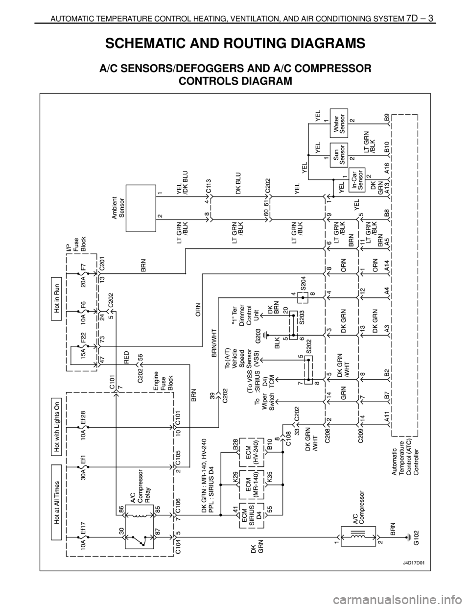
A/C SENSORS/DEFOGGERS AND A/C COMPRESSOR
CONTROLS DIAGRAM