2004 DAEWOO LACETTI Fuel tank
[x] Cancel search: Fuel tankPage 732 of 2643

1F – 486IENGINE CONTROLS
DAEWOO V–121 BL4
DIAGNOSTIC TROUBLE CODE (DTC) P0443
EVAPORATIVE EMISSION SYSTEM PURGE SOLENOID
CONTROL CIRCUIT
System Description
The Evaporative Emission (EVAP) system includes the
following components:
S Fuel tank
S Fuel tank pressure sensor.
S Fuel pipes and hoses.
S Fuel vapor lines.
S Fuel cap
S EVAP canister.
S Purge lines.
S EVAP emission canister purge solenoid valve.
S EVAP service port.
The EVAP purge canister solenoid is controlled by the En-
gine Control Module (ECM). The ECM applies a ground to
the EVAP purge canister solenoid. The ECM determines
when to activate the EVAP canister purge solenoid de-
pending on operating conditions, including Throttle Posi-
tion (TP), engine speed, Engine Coolant Temperature
(ECT) and ambient temperature.
The Diagnostic Trouble Code will detect an open or short
circuit.
Conditions for Setting the DTC
S Ignition ON.
S Ignition voltage is greater than 11 v.
Action Taken When the DTC SetsS The Malfunction Indicator Lamp (MIL) will illuminate
after three consecutive trip with a fail.
S The ECM will record operating conditions at the
time the diagnostic fails. This information will be
stored in the Freeze Frame and Failure Records
buffers.
S A history DTC is stored.
Conditions for Clearing the MIL/DTC
S The MIL will turn off after four consecutive ignition
cycles in which the diagnostic runs without a fault.
S A history DTC will clear after 40 consecutive warm–
up cycles without a fault.
S DTC(s) can be cleared by using a scan tool.
S Disconnecting the ECM battery feed for more than
10 seconds.
Diagnostic Aids
Using Freeze Frame and/or Failure Records data may aid
in locating an intermittent condition. If the DTC cannot be
duplicated, the information included in the Freeze Frame
and/or Failure Records data can be useful in determining
how many miles since the DTC set. The Fail Counter and
the Pass Counter can also be used to determine how
many ignition cycles the diagnostic reported a pass and/or
a fail. Operate the vehicle within the same freeze frame
conditions (rpm, load, vehicle speed, temperature, etc.)
that were noted. This will isolate when the DTC failed.
Page 736 of 2643

1F – 490IENGINE CONTROLS
DAEWOO V–121 BL4
DTC P0461 – Fuel Level Stuck
StepActionValue(s)YesNo
1Perform an On–Board Diagnostic (EOBD) System
Check.
Is the system check complete?–Go to Step 2Go to
”On–Board
Diagnostic Sys-
tem Check”
21. Install a scan tool to the Data Link Connector
(DLC).
2. Start the engine and operate the vehicle over
the specified mileage.
Is any of the Diagnostic trouble Codes (DTCs)
P0462, P0463 or P0502 set?250 km
(155 mile)Go to Applica-
ble DTC tableGo to Step 3
31. Turn the ignition OFF.
2. Disconnect the fuel pump connector.
3. Turn the ignition ON.
4. Using a voltmeter, measure the fuel level signal
voltage at the fuel level sensor connector ter-
minal 1.
Is the voltage within the specified value?4–5 voltsGo to Step 4Go to Step 5
41. Disconnect the Engine Control Module (ECM).
2. Check the fuel level sensor ground circuit for
an open between terminal 6 of the fuel sensor
connector and terminal K34 of the ECM and
repair as needed.
Is the repair complete?–Go to Step 10Go to Step 6
5Using a voltmeter, measure the voltage at the ECM
connector terminal K34 by back–probing the ECM
connector.
Is the voltage within the specified value?4–5 VGo to Step 8Go to Step 9
61. Remove the fuel pump from the fuel tank.
2. Reconnect the fuel pump connector.
3. Turn the ignition ON.
4. Monitor the fuel level sensor parameter on the
scan tool while moving the fuel sensor float
from empty position to full position.
5. Repeat procedure 4 several times.
Does the fuel level sensor vale on the scan tool in-
crease and then decrease steadily when the float is
moved?–Go to
”Diagnostic
Aids”Go to Step 7
71. Turn the ignition OFF.
2. Replace the fuel pump assembly.–Go to Step 10–
81. Turn the ignition OFF.
2. Disconnect the ECM connector.
3. Check the fuel level signal circuit fir an open or
short to ground between terminal K51 and fuel
pump harness connector terminal 1 and repair
as needed.
Is the repair complete?–Go to Step 10–
91. Turn the ignition OFF.
2. Replace the ECM.
Is the repair complete?–Go to Step 10–
Page 739 of 2643

ENGINE CONTROLS 1F – 493
DAEWOO V–121 BL4
DTC P0462 – Fuel Level Low Voltage
StepActionValue(s)YesNo
1Perform an On–Board Diagnostic (EOBD) System
Check.
Was the check performed?–Go to Step 2Go to
”On–Board
Diagnostic Sys-
tem Check”
21. Install a scan tool to the Data Link Connector
(DLC).
2. Start the engine and operate the vehicle within
Failure Record condition as noted.
Is Diagnostic trouble Codes (DTCs) P0462 set?–Go to Step 3Go to
”Diagnostic
Aids”
31. Turn the ignition OFF.
2. Disconnect the fuel pump connector.
3. Turn the ignition ON.
4. Using a voltmeter, measure the fuel level signal
voltage at the fuel level sensor connector ter-
minal 1.
Is the voltage within the specified value?0.4 – 4.5 VGo to Step 4Go to Step 6
4Check for a proper ground connection at the fuel
tank and repair as needed.
Is the repair complete?–Go to Step 11Go to Step 5
51. Remove the fuel pump from the fuel tank.
2. Reconnect the fuel pump connector.
3. Turn the ignition ON.
4. Monitor the fuel level sensor parameter on the
scan tool while moving the fuel sensor float
from empty position to full position.
5. Repeat procedure 4 several times.
Does the fuel level sensor vale on the scan tool in-
crease and then decrease steadily when the float is
moved?–Go to
”Diagnostic
Aids”Go to Step 8
6Check for an open or short to ground in the fuel level
sensor circuit and repair as needed.
Is the repair necessary?–Go to Step 11Go to Step 9
7Repair the open or short to ground in the fuel level
sensor circuit between the fuel level sensor harness
connector and fuel level sensor.
Is the repair complete?–Go to Step 11–
81. Turn the ignition OFF.
2. Replace the fuel pump assembly.
Is the repair complete?–Go to Step 11–
91. Turn the ignition OFF.
2. Connect the fuel pump connector.
3. Disconnect the engine Control Module (ECM)
connector.
4. Turn the ignition ON.
5. Using a digital voltmeter, measure the voltage
in the signal circuit at terminal K51.
Is the voltage within the specified value?4–5 VGo to Step 10Go to
Section 9E, In-
strumentation/
Driver Informa-
tion
10S Turn the ignition OFF.
S Replace the ECM.
Is the repair complete?–Go to Step 11–
Page 742 of 2643

1F – 496IENGINE CONTROLS
DAEWOO V–121 BL4
DTC P0463 – Fuel Level High Voltage
StepActionValue(s)YesNo
1Perform an On–Board Diagnostic (EOBD) System
Check.
Was the check performed?–Go to Step 2Go to
”On–Board
Diagnostic Sys-
tem Check”
21. Install a scan tool to the Data Link Connector
(DLC).
2. Start the engine and operate the vehicle within
Failure Record condition as noted.
Is Diagnostic trouble Codes (DTCs) P0463 set?–Go to Step 3Go to
”Diagnostic
Aids”
31. Turn the ignition OFF.
2. Disconnect the fuel pump connector.
3. Turn the ignition ON.
4. Using a voltmeter, measure the fuel level signal
voltage at the fuel level sensor connector ter-
minal 1.
Is the voltage within the specified value?0.4 – 4.5 VGo to Step 4Go to Step 6
4Check for a proper ground connection at the fuel
tank and repair as needed.
Is the repair necessary?–Go to Step 11Go to Step 5
51. Remove the fuel pump from the fuel tank.
2. Reconnect the fuel pump connector.
3. Turn the ignition ON.
4. Monitor the fuel level sensor parameter on the
scan tool while moving the fuel sensor float
from empty position to full position.
5. Repeat procedure 4 several times.
Does the fuel level sensor vale on the scan tool in-
crease and then decrease steadily when the float is
moved?–Go to
”Diagnostic
Aids”Go to Step 8
6Check for short to voltage in the fuel level sensor cir-
cuit and repair as needed.
Is the repair necessary?–Go to Step 7Go to Step 9
7Repair the short to voltage in the fuel level sensor cir-
cuit between the fuel level sensor harness connector
and fuel level sensor.
Is the repair necessary?–Go to Step 11–
8S Turn the ignition OFF.
S Replace the fuel pump assembly.
Is the repair complete? –Go to Step 11–
91. Turn the ignition OFF.
2. Connect the fuel pump connector.
3. Disconnect the engine Control Module (ECM )
connector.
4. Turn the ignition ON.
5. Using a digital voltmeter, measure the voltage
in the signal circuit at terminal K51.
Is the voltage within the specified value?0.4 – 4.5 VGo to Step 10Go to
Section 9E, In-
strumentation/
Driver Informa-
tion
10S Turn the ignition OFF.
S Replace the ECM.
Is the repair complete?–Go to Step 11–
Page 794 of 2643

1F – 548IENGINE CONTROLS
DAEWOO V–121 BL4
DIAGNOSTIC TROUBLE CODE (DTC) P1171
FUEL TRIM SYSTEM LEAN DURING POWER
ENRICHMENT
System Description
The internal circuitry of the Engine control Module (ECM)
can identify if the vehicle fuel system is capable of supply-
ing adequate amounts of fuel during heavy acceleration(
power enrichment). When a Power Enrichment (PE)
mode of operation is requested by heavy acceleration dur-
ing Closed Loop operation, the ECM will provide more fuel
to the engine. Under these conditions the ECM should de-
tect a rich condition. If this reich condition is nor detected
at this time, Diagnostic Trouble Code (DTC) P1171 will set.
A plugged fuel filter or restricted fuel line can prevent ade-
quate amount of fuel from being supplied during Power
Enrichment mode.
Conditions for Setting the DTC
S HO2S1 voltage is less than 0.35 volts in Power En-
richment (PE) mode.
S Engine is operating in Closed Loop and in PE
mode.
S Engine Coolant Temperature (ECT) is greater than
60°C (140°F).
S System voltage is greater than 10 volts.
S Air/Fuel ration is less than 13.5:1.
S DTCs P0106, P0107, P0108, P0117, P0118,
P0122, P0123, P0171, P0172, P0201, P0202,
P0203, P0204, P0300, P0336, P0337, P0351,
P0352, P0402, P0404, P0405, P0406, P0506,
P0507, P1404, and P0443 are not set.
S 3 second delay after in PE mode.
Action Taken When the DTC Sets
S The Malfunction Indicator Lamp (MIL) will illuminate
after two consecutive ignition cycle with a fail.
S The ECM will record operating conditions at the
time the diagnostic fails. This information will be
stored in the Freeze Frame and Failure Records
buffers.
S A history DTC is stored.
S The vehicle will operate in Open Loop.Conditions for Clearing the MIL/DTC
S The MIL will turn off after three consecutive ignition
cycles in which the diagnostic runs without a fault.
S A history DTC will clear after 40 consecutive warm–
up cycles without a fault.
S DTC(s) can be cleared by using the scan tool.
S Disconnecting the ECM battery feed for more than
10 seconds.v
Diagnostic Aids
A restricted fuel filter can supply adequate amounts of fuel
at idle, but may not be able to supply enough fuel during
heavy acceleration.
Water or alcohol n fuel may cause low HO2S1 voltage dur-
ing acceleration.
Check for adequate amount of fuel in the Tank.
When the engine is idling or at steady cruise, the HO2S1
voltage should vary from between approximately a00 to
900 millivolts. During power enrichment mode, more fuel
is needed, and the HO2S1 should rise above 444 milli-
volts.
Check for faulty or plugged injector(s).
Test Description
Number(s) below refer to the step number(s) on the Diag-
nostic Table.
1. The On–Board Diagnostic (EOBD) System Check
prompts the technician to complete some basic
checks and store the freeze frame and failure re-
cords data on the scan tool if applicable. This
creates an electronic copy of the data taken when
the malfunction occurred. The information is then
stored on the scan tool for later reference.
4. This step checks to see if the HO2S1 is operating
properly.
6. If no faults have been found at this point and no
additional DTCs were set, refer to ”Diagnostic Aids”
in this section for additional checks and informa-
tion.
Page 795 of 2643

ENGINE CONTROLS 1F – 549
DAEWOO V–121 BL4
DTC P1171 – Fuel Trim Supply System Lean During Power
Enrichment
StepActionValue(s)YesNo
1Perform an On–Board Diagnostic (EOBD) System
Check.
Is the system check complete?–Go to Step 2Go to
”On–Board
Diagnostic Sys-
tem Check”
21. Install a scan tool to the Data Link Connector
(DLC).
2. Turn the ignition ON.
Are any component related Diagnostic Trouble
Codes (DTCs) set?–Go to
applicable DTC
tableGo to Step 3
31. Check the vehicle for an adequate amount of
fuel.
2. Add fuel to the vehicles fuel tank if the tank is
almost empty.
Did the fuel tank require fuel?–Go to Step 5Go to Step 4
41. Using a scan tool, observe the Front Heated
Oxygen Sensor (HO2S1) voltage while acceler-
ating the engine over 1200 rpm.
2. The HO2S1 voltage should vary from specified
voltage (100––900 mV) and occasionally toggle
above the specified voltage while accelerating.
Is the HO2S1 voltage toggle?3507 mVGo to
”Fuel System
Diagnosis”Go to
”DTC P0134
Oxygen Sensor
No Activity”
51. Using the scan tool, clear the Diagnostic
Trouble Codes (DTCs).
2. Start the engine and idle at normal operating
temperature.
3. Operate the vehicle within the conditions for
setting this DTC as specified in the supporting
text.
Does the scan tool indicate that this diagnostic has
run and passed?–Go to Step 6Go to Step 2
6Check if any additional DTCs are set.
Are any DTCs displayed that have not been diag-
nosed?–Go to
Applicable DTC
tableSystem OK
Page 840 of 2643

1F – 594IENGINE CONTROLS
DAEWOO V–121 BL4
MAINTENANCE AND REPAIR
ON–VEHICLE SERVICE
FUEL SYSTEM PRESSURE RELIEF
Procedure
CAUTION : The fuel system is under pressure. To
avoid fuel spillage and the risk of personal injury or
fire, it is necessary to relieve the fuel system pressure
before disconnecting the fuel lines.
1. Remove the fuel cap.
2. Remove the fuel pump fuse Ef18 from the engine
fuse block.
3. Start the engine and allow the engine to stall.
4. Crank the engine for an additional 10 seconds.
FUEL TANK
Removal Procedure
CAUTION : The fuel system is under pressure. To
avoid fuel spillage and the risk of personal injury or
fire, it is necessary to relieve the fuel system pressure
before disconnecting the fuel lines.
1. Relieve the fuel pressure. Refer to ” Fuel System
Pressure Relief ” in this section.
2. Disconnect the negative battery cable.
3. Drain the fuel tank.
4. Remove the front muffler. Refer to Section 1G, Ex-
haust System
5. Remove the fuel tank filler tube clamp at the fuel
tank.
6. Disconnect the fuel tank filler tube.
7. Disconnect the fuel vapor line near the fuel tank
filler tube.
8. Disconnect the fuel pump harness connector.
Page 841 of 2643
ENGINE CONTROLS 1F – 595
DAEWOO V–121 BL4
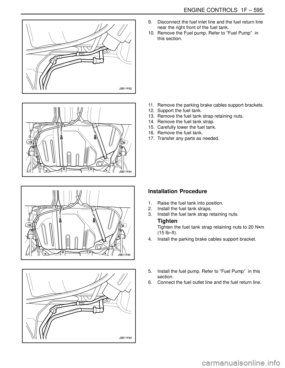
9. Disconnect the fuel inlet line and the fuel return line
near the right front of the fuel tank.
10. Remove the Fuel pump. Refer to ”Fuel Pump” in
this section.
11. Remove the parking brake cables support brackets.
12. Support the fuel tank.
13. Remove the fuel tank strap retaining nuts.
14. Remove the fuel tank strap.
15. Carefully lower the fuel tank.
16. Remove the fuel tank.
17. Transfer any parts as needed.
Installation Procedure
1. Raise the fuel tank into position.
2. Install the fuel tank straps.
3. Install the fuel tank strap retaining nuts.
Tighten
Tighten the fuel tank strap retaining nuts to 20 NSm
(15 lb–ft).
4. Install the parking brake cables support bracket.
5. Install the fuel pump. Refer to ”Fuel Pump” in this
section.
6. Connect the fuel outlet line and the fuel return line.