2004 DAEWOO LACETTI steering wheel
[x] Cancel search: steering wheelPage 1004 of 2643
MANUAL TRANSAXLE DRIVE AXLE 3B – 5
DAEWOO V–121 BL4
MAINTENANCE AND REPAIR
ON–VEHICLE SERVICE
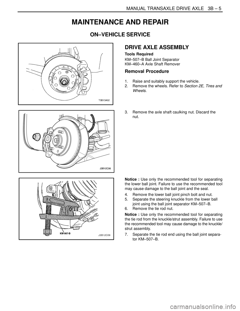
DRIVE AXLE ASSEMBLY
Tools Required
KM–507–B Ball Joint Separator
KM–460–A Axle Shaft Remover
Removal Procedure
1. Raise and suitably support the vehicle.
2. Remove the wheels. Refer to Section 2E, Tires and
Wheels.
3. Remove the axle shaft caulking nut. Discard the
nut.
Notice : Use only the recommended tool for separating
the lower ball joint. Failure to use the recommended tool
may cause damage to the ball joint and the seal.
4. Remove the lower ball joint pinch bolt and nut.
5. Separate the steering knuckle from the lower ball
joint using the ball joint separator KM–507–B.
6. Remove the tie rod nut.
Notice : Use only the recommended tool for separating
the tie rod from the knuckle/strut assembly. Failure to use
the recommended tool may cause damage to the knuckle/
strut assembly.
7. Separate the tie rod end using the ball joint separa-
tor KM–507–B.
Page 1030 of 2643
4A – 14IHYDRAULIC BRAKES
DAEWOO V–121 BL4
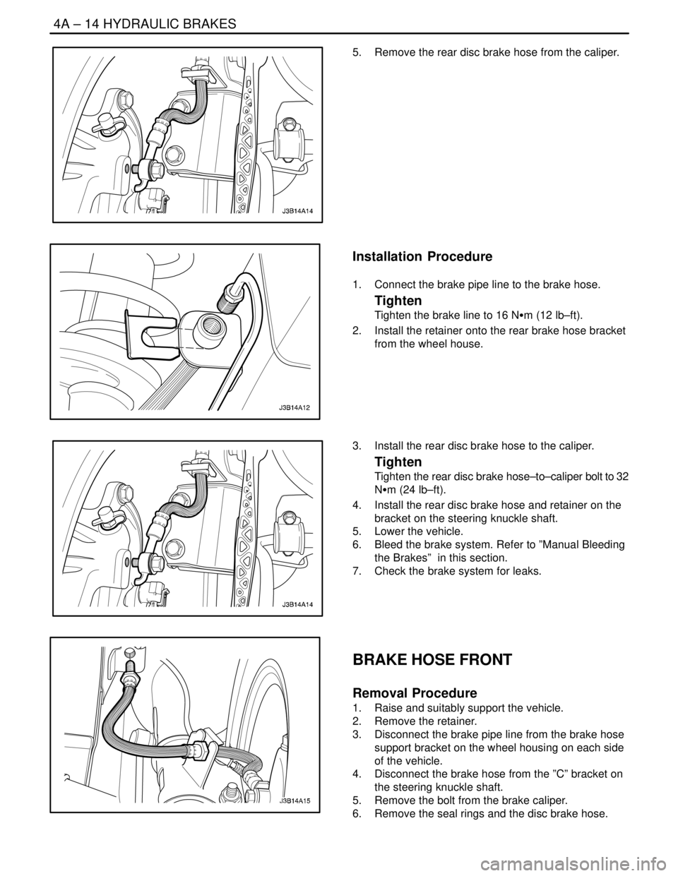
5. Remove the rear disc brake hose from the caliper.
Installation Procedure
1. Connect the brake pipe line to the brake hose.
Tighten
Tighten the brake line to 16 NSm (12 lb–ft).
2. Install the retainer onto the rear brake hose bracket
from the wheel house.
3. Install the rear disc brake hose to the caliper.
Tighten
Tighten the rear disc brake hose–to–caliper bolt to 32
NSm (24 lb–ft).
4. Install the rear disc brake hose and retainer on the
bracket on the steering knuckle shaft.
5. Lower the vehicle.
6. Bleed the brake system. Refer to ”Manual Bleeding
the Brakes” in this section.
7. Check the brake system for leaks.
BRAKE HOSE FRONT
Removal Procedure
1. Raise and suitably support the vehicle.
2. Remove the retainer.
3. Disconnect the brake pipe line from the brake hose
support bracket on the wheel housing on each side
of the vehicle.
4. Disconnect the brake hose from the ”C” bracket on
the steering knuckle shaft.
5. Remove the bolt from the brake caliper.
6. Remove the seal rings and the disc brake hose.
Page 1031 of 2643
HYDRAULIC BRAKES 4A – 15
DAEWOO V–121 BL4
Installation Procedure
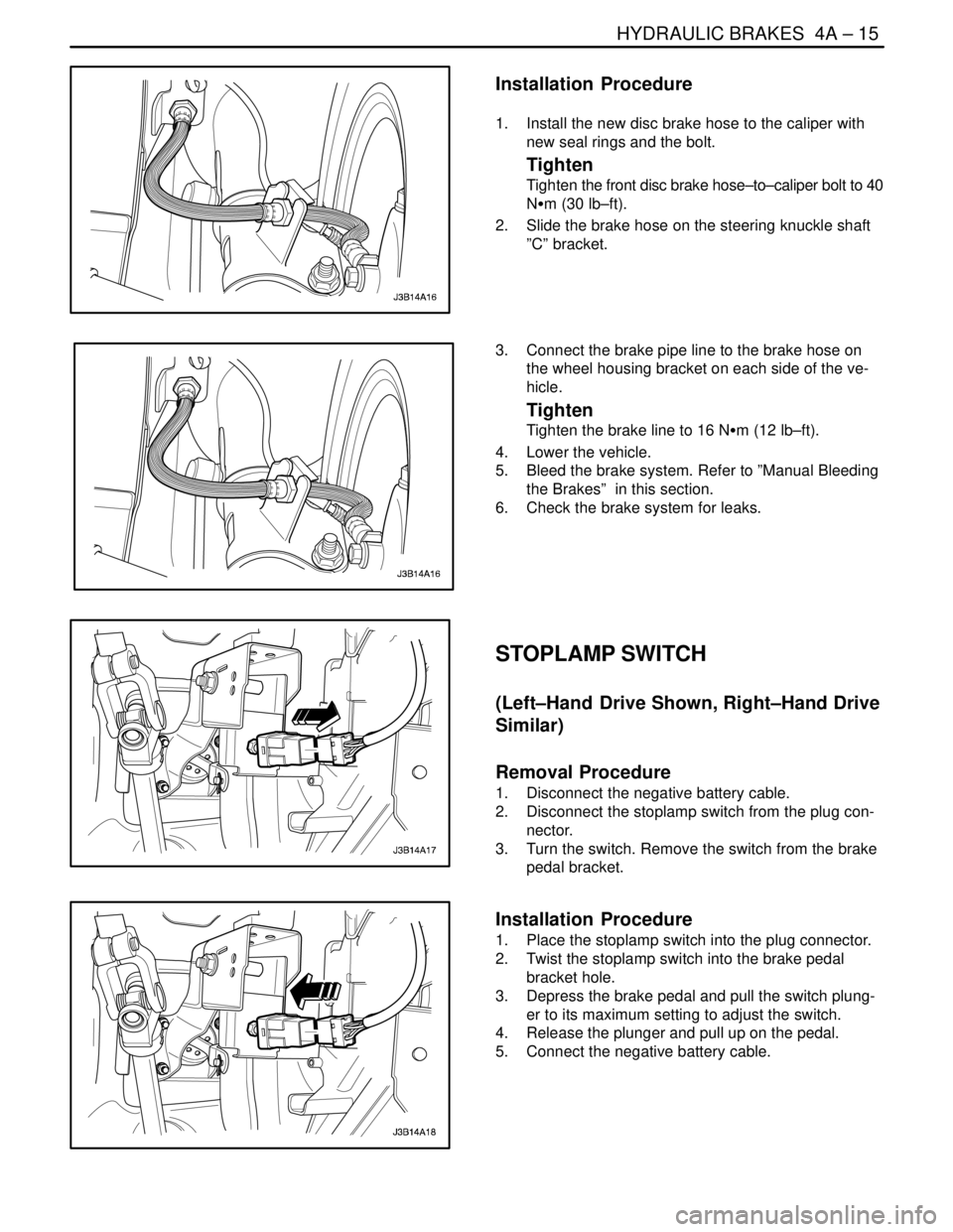
1. Install the new disc brake hose to the caliper with
new seal rings and the bolt.
Tighten
Tighten the front disc brake hose–to–caliper bolt to 40
NSm (30 lb–ft).
2. Slide the brake hose on the steering knuckle shaft
”C” bracket.
3. Connect the brake pipe line to the brake hose on
the wheel housing bracket on each side of the ve-
hicle.
Tighten
Tighten the brake line to 16 NSm (12 lb–ft).
4. Lower the vehicle.
5. Bleed the brake system. Refer to ”Manual Bleeding
the Brakes” in this section.
6. Check the brake system for leaks.
STOPLAMP SWITCH
(Left–Hand Drive Shown, Right–Hand Drive
Similar)
Removal Procedure
1. Disconnect the negative battery cable.
2. Disconnect the stoplamp switch from the plug con-
nector.
3. Turn the switch. Remove the switch from the brake
pedal bracket.
Installation Procedure
1. Place the stoplamp switch into the plug connector.
2. Twist the stoplamp switch into the brake pedal
bracket hole.
3. Depress the brake pedal and pull the switch plung-
er to its maximum setting to adjust the switch.
4. Release the plunger and pull up on the pedal.
5. Connect the negative battery cable.
Page 1049 of 2643

SECTION : 4D
FRONT DISC BRAKES
TABLE OF CONTENTS
SPECIFICATIONS4D–1 . . . . . . . . . . . . . . . . . . . . . . . . . .
Fastener Tightening Specirications 4D–1. . . . . . . . . .
DIAGNOSIS4D–1 . . . . . . . . . . . . . . . . . . . . . . . . . . . . . . . .
Lining Inspection 4D–1. . . . . . . . . . . . . . . . . . . . . . . . . .
Rotor Inspection 4D–1. . . . . . . . . . . . . . . . . . . . . . . . . .
MAINTENANCE AND REPAIR4D–3 . . . . . . . . . . . . . . .
ON–VEHICLE SERVICE 4D–3. . . . . . . . . . . . . . . . . . . . .
Shoe and Lining 4D–3. . . . . . . . . . . . . . . . . . . . . . . . . . Caliper Assembly 4D–3. . . . . . . . . . . . . . . . . . . . . . . . . .
Rotor 4D–4. . . . . . . . . . . . . . . . . . . . . . . . . . . . . . . . . . . .
Splash Shield 4D–5. . . . . . . . . . . . . . . . . . . . . . . . . . . . .
UNIT REPAIR 4D–6. . . . . . . . . . . . . . . . . . . . . . . . . . . . . .
Caliper Overhaul 4D–6. . . . . . . . . . . . . . . . . . . . . . . . . .
GENERAL DESCRIPTION AND SYSTEM
OPERATION4D–9 . . . . . . . . . . . . . . . . . . . . . . . . . . . . . .
Disc Brake Caliper Assembly 4D–9. . . . . . . . . . . . . . . .
SPECIFICATIONS
FASTENER TIGHTENING SPECIRICATIONS
ApplicationNSmLb–FtLb–In
Brake Hose Inlet Fitting–to–Caliper Bolt4030–
Caliper Bleeder Valve8–71
Caliper–to–Steering Knuckle Mounting Bolts9570–
Retaining Frame–to–Caliper Housing Bolts2720–
Rotor–to–Front Wheel Hub Detent Screw4–35
Splash Shield–to–Steering Knuckle Screws4–35
DIAGNOSIS
LINING INSPECTION
1. Raise and suitably support the vehicle.
2. Remove the front wheels. Refer to Section 2E,
Tires and Wheels.
3. Visually check the linings for minimum thickness
and wear.
4. Measure the thickness.
Important : The minimum thickness of the inner or the
outer pad is 7 mm (0.28 inch).
5. Install the brake pads in axle sets only.
6. Install the front wheels. Refer to Section 2E, Tires
and Wheels.
7. Lower the vehicle.ROTOR INSPECTION
Thickness variation can be checked by measuring the
thickness of the rotor at four or more points around the cir-
cumference of the rotor. All measurements must be made
at the same distance in from the edge of the rotor.
A rotor that varies by more than 0.01 mm (0.0004 inch) can
cause pedal pulsations and/or front end vibration during
brake applications. A rotor that does not meet these speci-
fications should be refinished to specifications or re-
placed.
Page 1052 of 2643
4D – 4IFRONT DISC BRAKES
DAEWOO V–121 BL4
Installation Procedure
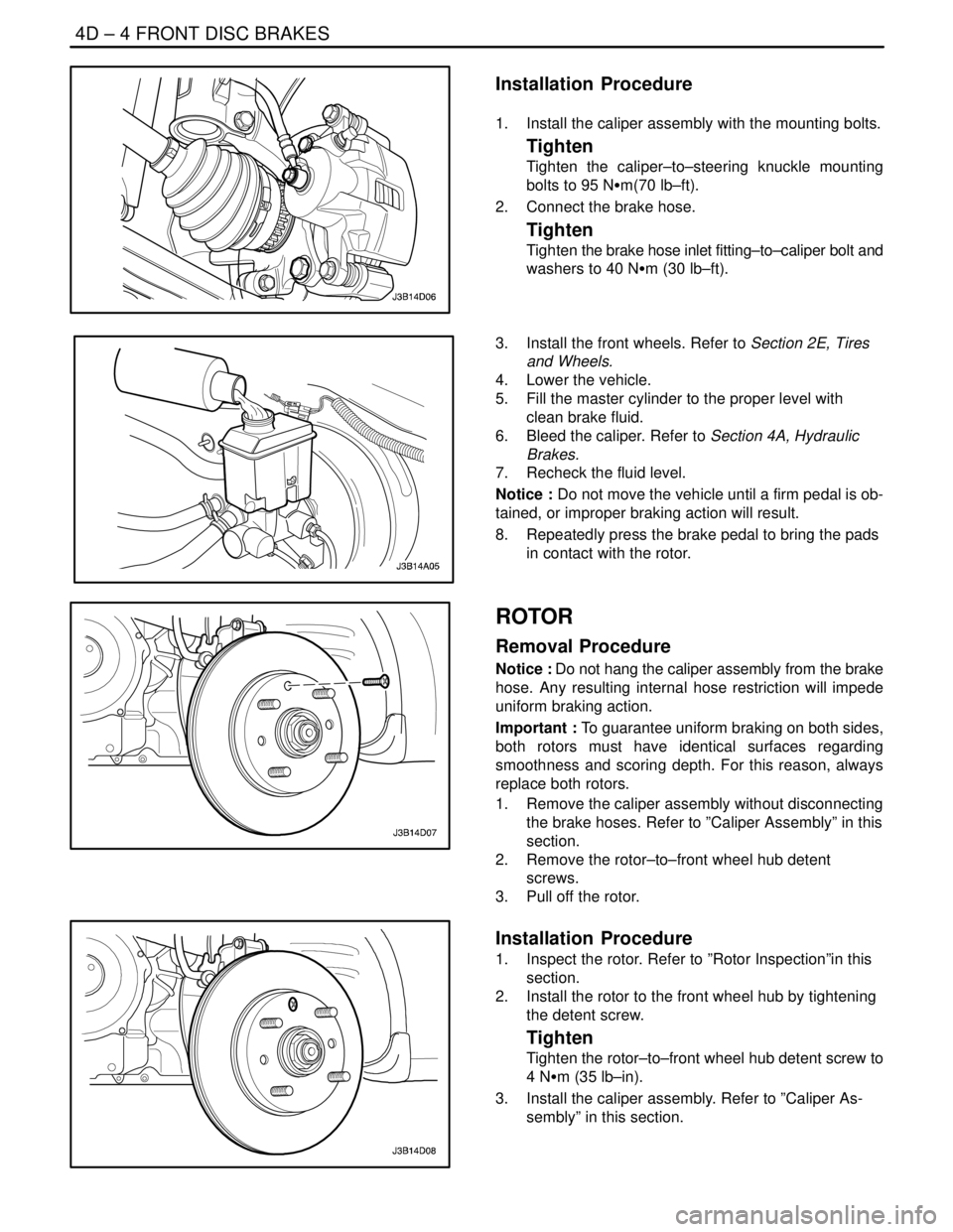
1. Install the caliper assembly with the mounting bolts.
Tighten
Tighten the caliper–to–steering knuckle mounting
bolts to 95 NSm(70 lb–ft).
2. Connect the brake hose.
Tighten
Tighten the brake hose inlet fitting–to–caliper bolt and
washers to 40 NSm (30 lb–ft).
3. Install the front wheels. Refer to Section 2E, Tires
and Wheels.
4. Lower the vehicle.
5. Fill the master cylinder to the proper level with
clean brake fluid.
6. Bleed the caliper. Refer to Section 4A, Hydraulic
Brakes.
7. Recheck the fluid level.
Notice : Do not move the vehicle until a firm pedal is ob-
tained, or improper braking action will result.
8. Repeatedly press the brake pedal to bring the pads
in contact with the rotor.
ROTOR
Removal Procedure
Notice : Do not hang the caliper assembly from the brake
hose. Any resulting internal hose restriction will impede
uniform braking action.
Important : To guarantee uniform braking on both sides,
both rotors must have identical surfaces regarding
smoothness and scoring depth. For this reason, always
replace both rotors.
1. Remove the caliper assembly without disconnecting
the brake hoses. Refer to ”Caliper Assembly” in this
section.
2. Remove the rotor–to–front wheel hub detent
screws.
3. Pull off the rotor.
Installation Procedure
1. Inspect the rotor. Refer to ”Rotor Inspection”in this
section.
2. Install the rotor to the front wheel hub by tightening
the detent screw.
Tighten
Tighten the rotor–to–front wheel hub detent screw to
4 NSm (35 lb–in).
3. Install the caliper assembly. Refer to ”Caliper As-
sembly” in this section.
Page 1143 of 2643
4F – 62IANTILOCK BRAKE SYSTEM
DAEWOO V–121 BL4
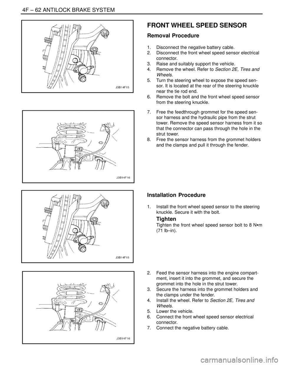
FRONT WHEEL SPEED SENSOR
Removal Procedure
1. Disconnect the negative battery cable.
2. Disconnect the front wheel speed sensor electrical
connector.
3. Raise and suitably support the vehicle.
4. Remove the wheel. Refer to Section 2E, Tires and
Wheels.
5. Turn the steering wheel to expose the speed sen-
sor. It is located at the rear of the steering knuckle
near the tie rod end.
6. Remove the bolt and the front wheel speed sensor
from the steering knuckle.
7. Free the feedthrough grommet for the speed sen-
sor harness and the hydraulic pipe from the strut
tower. Remove the speed sensor harness from it so
that the connector can pass through the hole in the
strut tower.
8. Free the sensor harness from the grommet holders
and the clamps and pull it through the fender.
Installation Procedure
1. Install the front wheel speed sensor to the steering
knuckle. Secure it with the bolt.
Tighten
Tighten the front wheel speed sensor bolt to 8 NSm
(71 lb–in).
2. Feed the sensor harness into the engine compart-
ment, insert it into the grommet, and secure the
grommet into the hole in the strut tower.
3. Secure the harness into the grommet holders and
the clamps under the fender.
4. Install the wheel. Refer to Section 2E, Tires and
Wheels.
5. Lower the vehicle.
6. Connect the front wheel speed sensor electrical
connector.
7. Connect the negative battery cable.
Page 1152 of 2643

ANTILOCK BRAKE SYSTEM 4F – 71
DAEWOO V–121 BL4
TIRES AND ABS/EBD
Replacement Tires
Tire size is important for proper performance of the ABS
system. Replacement tires should be the same size, load
range, and construction as the original tires. Replace tires
in axle sets and only with tires of the same tire perfor-
mance criteria (TPC) specification number. Use of any
other size or type may seriously affect the ABS operation.
TIRES AND ABS/EBD
Notice : There is no serviceable or removable EEPROM.
The EBCM must be replaced as an assembly.
The EBCM is attached to the hydraulic unit in the engine
compartment. The controlling element of ABS 5.3 is a mi-
croprocessor–based EBCM. Inputs to the system include
the four wheel speed sensors, the stoplamp switch, the
ignition switch, and the unswitched battery voltage. There
is an output to a bi–directional serial data link, located in
pin K of Data Link Connector (DLC) for service diagnostic
tools and assembly plant testing.
The EBCM monitors the speed of each wheel. If any wheel
begins to approach lockup and the brake switch is closed
(brake pedal depressed), the EBCM controls the sole-
noids to reduce brake pressure to the wheel approaching
lockup. Once the wheel regains traction, brake pressure
is increased until the wheel again begins to approach lock-
up. This cycle repeats until either the vehicle comes to a
stop, the brake pedal is released, or no wheels approach
lockup.
Additionally, the EBCM monitors itself, each input (except
the serial data link), and each output for proper operation.
If it detects any system malfunction, the EBCM will store
a DTC in nonvolatile memory (EEPROM) (DTCs will not
disappear if the battery is disconnected). Refer to ”Self
Diagnostics” in this section for more detailed information.
FRONT WHEEL SPEED SENSOR
The front wheel speed sensors are of a variable reluctance
type. Each sensor is attached to the steering knuckle,
close to a toothed ring. The result, as teeth pass by the
sensor, is an AC voltage with a frequency proportional to
the speed of the wheel. The magnitude of the voltage and
frequency increase with increasing speed. The sensor is
not repairable, nor is the air gap adjustable.
FRONT WHEEL SPEED SENSOR
RINGS
The toothed ring mentioned above is pressed onto the
wheel–side (outer) constant velocity joint. Each ring con-
tains 47 equally spaced teeth. Exercise care during ser-
vice procedures to avoid prying or contacting this ring. Ex-cessive contact may cause damage to one or more teeth.
If the ring is damaged, the wheel–side constant velocity
joint must be replaced.
REAR WHEEL SPEED SENSOR AND
RINGS
The rear wheel speed sensors operate in the same man-
ner as the front wheel speed sensors. They incorporate a
length of flexible harness with the connector attached to
the end of the harness. The rear wheel speed rings are in-
corporated into the hub assemblies and cannot be re-
placed separately, but require replacement of the rear
hub/bearing assembly.
VALUE RELAY AND PUMP MOTOR
RELAY
The valve relay and the motor pump relay are located in-
side the electronic brake control module (EBCM) and are
not replaceable. If one should fail, replace the EBCM.
WIRING HARNESS
The wiring harness is the mechanism by which the elec-
tronic brake control module (EBCM) is electrically con-
nected to power and to ground, to the wheel speed sen-
sors, the fuses, the switches, the indicators, and the serial
communications port. The components, considered part
of the wiring harness, are the wires that provide electrical
interconnection, and connectors (terminals, pins, con-
tacts, or lugs) that provide an electrical/mechanical inter-
face from the wire to a system component.
INDICATORS
The electronic brake control module (EBCM) continuously
monitors itself and the other ABS components. If the
EBCM detects a problem with the system, the amber ABS
indicator will light continuously to alert the driver to the
problem. An illuminated ABS indicator indicates that the
ABS system has detected a problem that affects the op-
eration of ABS. No antilock braking will be available. Nor-
mal, non–antilock brake performance will remain. In order
to regain ABS braking ability, the ABS must be serviced.
The red BRAKE indicator will be illuminated when the sys-
tem detects a low brake fluid level in the master cylinder
or when the parking brake switch is closed (the parking
brake is engaged) or EBD system is diabled.
WARNING : EBD INDICATOR LAMP WIRING IS CON-
NECTED TO THE PARKING BRAKE LAMP. IF THE
PARKING BRAKE LAMP IS TURNED ON WHEN YOU
DRIVING, CHECKING ON WHETHER THE PARKING
BRAKE LEVER IS ENAGED OR THE BRAKE FLUID
LEVEL IS LOW. IF THE SYSTEM HAS NO PROBLEM,
THE EBD SYSTEM IS WORKING IMPROPERLY. THE
EBD SYSTEM MUST BE SERVICED.
Page 1903 of 2643

6A – 2IPOWER STEERING SYSTEM
DAEWOO V–121 BL4
DIAGNOSIS
POWER STEERING SYSTEM
PRESSURE TEST
Tools Required
KM–354–B Pressure Test Gauge Kit
Check the fluid pressure as follows to determine whether
the trouble is in the pump or the gear unit.
Test Procedure
1. Check the power steering fluid level and the power
steering pump belt tension. Refer to ”Checking and
Adding Fluid” in this section and Section 6B, Power
Steering Pump.
2. Disconnect the high pressure line at the pump. Use
a small container to catch any fluid.
3. Connect the hose of the pressure test gauge kit
KM–354–B to the power steering pressure hose
from the power steering pump.
4. Place the gear selector lever in PARK (automatic
transaxle–equipped vehicles) or NEUTRAL (manual
transaxle–equipped vehicles). Set the parking
brake.
5. Open the gauge valve fully.
6. Start the engine and let it idle.
7. Turn the steering wheel from lock to lock several
times to warm the fluid to operating temperature.
8. Increase the engine speed to 1,500 rpm.
Notice : The power steering pump could be damaged if
the valve is fully closed for more than 5 seconds.
9. Close the gauge valve fully, and read the pressure.
The pump pressure with the valve closed should be
between 8,330 kPa to 8,820 kPa (1,208 psi to
1,279 psi). With electronic variable orifice, the pres-
sure should be between 8,500 kPa to 8,960 kPa
(1,233 psi to 1,299 psi).
10. Immediately open the gauge valve fully.
11. Turn the steering wheel all the way to the left and
the right. If the pressure is within the specified lim-
its, the problem is not in the pump. Check the pow-
er steering gear for leaks.
POWER STEERING SYSTEM LEAK
TEST
General Procedure
Inspect the following:
S The fluid reservoir for overfill.
S Fluid for aeration and overflow.
S The hoses for loose connections.
S The torsion bar, stub shaft and adjuster seals for
leaks.
S The component sealing surfaces for damage.
Important : Verify the exact point of the leak. The point
from which the fluid is dripping is not necessarily the point
at which the system is leaking. When service is required,
clean the leak area upon disassembly, replace the leaking
seal, check the component sealing surfaces for damage
and reset the torque bolt to specifications, where required.
External Leak Check
The purpose of this procedure is to pinpoint the location of
the leak. In some cases, the leak can be easily located, but
seepage–type leaks may be harder to find. To locate seep-
age leaks, use the following method:
1. With the engine off, wipe dry the complete power
steering system.
2. Check the power steering fluid level in the pump’s
reservoir. Adjust the fluid level as necessary. Refer
to ”Checking and Adding Fluid” in this section.
Notice : Do not hold the steering wheel at a stop for any
length of time as this can damage the power steering
pump.
3. Start the engine. Turn the steering wheel counter-
clockwise and clockwise from stop to stop several
times.
4. Find the exact area of the leak and repair it.