2004 DAEWOO LACETTI brake
[x] Cancel search: brakePage 910 of 2643

WHEEL ALIGNMENT 2B – 3
DAEWOO V–121 BL4
4. Install original tires one at a time to find the offend-
ing tire.
RADIAL TIRE LEAD/PULL
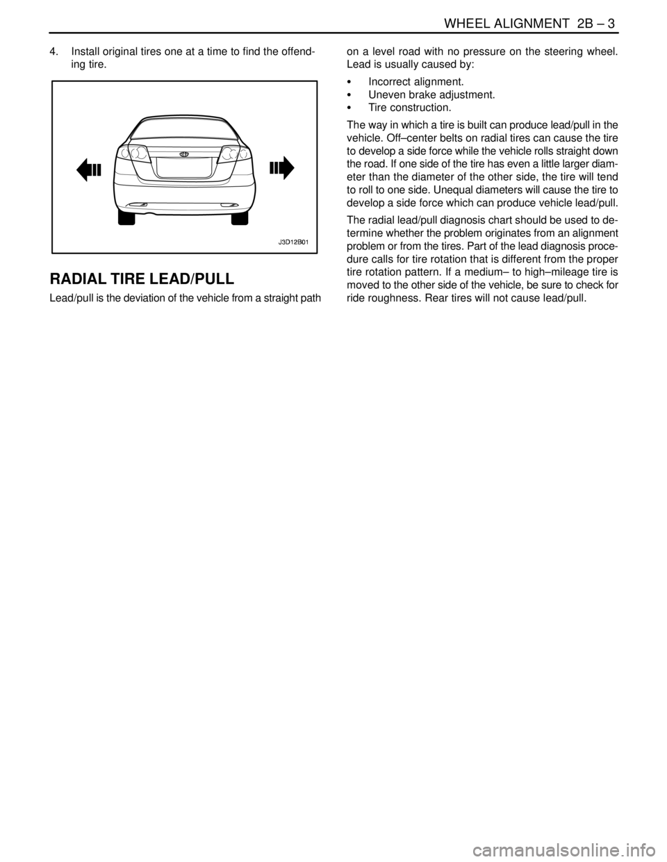
Lead/pull is the deviation of the vehicle from a straight pathon a level road with no pressure on the steering wheel.
Lead is usually caused by:
S Incorrect alignment.
S Uneven brake adjustment.
S Tire construction.
The way in which a tire is built can produce lead/pull in the
vehicle. Off–center belts on radial tires can cause the tire
to develop a side force while the vehicle rolls straight down
the road. If one side of the tire has even a little larger diam-
eter than the diameter of the other side, the tire will tend
to roll to one side. Unequal diameters will cause the tire to
develop a side force which can produce vehicle lead/pull.
The radial lead/pull diagnosis chart should be used to de-
termine whether the problem originates from an alignment
problem or from the tires. Part of the lead diagnosis proce-
dure calls for tire rotation that is different from the proper
tire rotation pattern. If a medium– to high–mileage tire is
moved to the other side of the vehicle, be sure to check for
ride roughness. Rear tires will not cause lead/pull.
Page 911 of 2643

2B – 4IWHEEL ALIGNMENT
DAEWOO V–121 BL4
Radial Tire Lead/Pull Diagnosis Chart
StepActionValue(s)YesNo
11. Perform wheel alignment preliminary inspec-
tion.
2. Check the brakes for dragging.
3. Road test the vehicle.
Does the vehicle lead/pull?–Go to Step 2System OK
21. Cross switch the front tire and wheel assem-
blies.
2. Road test the vehicle.
Does the vehicle lead/pull?–Go to Step 3System OK
3Check the front wheel alignment.
Is the alignment within specifications?–Go to Step 4Adjust
alignment
4Compare the front camber and front caster to speci-
fications.
Are they within specifications?–Go to Step 7Go to Step 5
5Check the vehicle frame.
Is the frame bent?–Go to Step 6Go to Step 1
6Straighten the frame.
Is the repair complete?–Go to Step 3–
71. The probable cause is the tires.
2. Switch the left front tire and wheel assembly
with the left rear tire and wheel assembly.
3. Road test the vehicle.
Does the vehicle still lead/pull?–Go to Step 9Go to Step 8
8Switch the left front tire and wheel assembly with the
left rear tire and wheel assembly and replace the left
front tire.
Is the repair complete?–System OKGo to Step 1
91. Switch the right front tire and wheel assembly
with the right rear tire and wheel assembly.
2. Road test the vehicle.
Does the vehicle still lead/pull?–Go to Step 1Go to Step 10
10Switch the right front tire and wheel assembly with
the right rear tire and wheel assembly and replace
the right front tire.
Is the repair complete?–System OKGo to Step 1
Page 912 of 2643

WHEEL ALIGNMENT 2B – 5
DAEWOO V–121 BL4
VIBRATION DIAGNOSIS
Wheel imbalance causes most highway speed vibration
problems. A vibration can remain after dynamic balancing
because:
S A tire is out of round.
S A rim is out of round.
S A tire stiffness variation exists.
Measuring tire and wheel free runout will uncover only part
of the problem. All three causes, known as loaded radial
runout, must be checked using method of substituting
known good tire and wheel assemblies on the problem ve-
hicle.
Low–speed vibrations, which occur below 64 km/h (40
mph), are usually caused by runout. High–speed vibra-
tions, which occur above 64 km/h (40 mph), can be caused
by either imbalance or runout.
Preliminary Checks
Prior to performing any work, always road test the car and
perform a careful visual inspection for:
S Obvious tire and wheel runout.
S Obvious drive axle runout.
S Improper tire inflation.
S Incorrect trim height.
S Bent or damaged wheels.
S Debris build–up on the tire or the wheel.
S Irregular or excessive tire wear.
S Improper tire bead seating on the rim.
S Imperfections in the tires, including: tread deforma-
tions, separations, or bulges from impact damage.
Slight sidewall indentations are normal and will not
affect ride quality.
Tire Balancing
Balance is the easiest procedure to perform and should be
done first if the vibration occurs at high speeds. Do an off–
vehicle, two–plane dynamic balance first to correct any im-
balance in the tire and wheel assembly.
An on–vehicle finish balance will correct any brake drum,
rotor, or wheel cover imbalance. If balancing does not cor-
rect the high–speed vibration, or if the vibration occurs at
low speeds, runout is the probable cause.
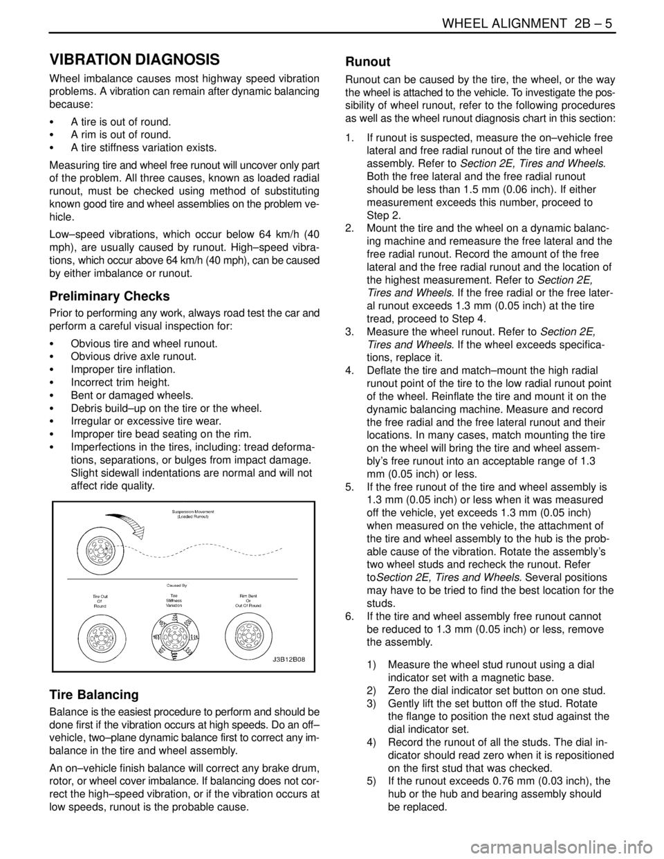
Runout
Runout can be caused by the tire, the wheel, or the way
the wheel is attached to the vehicle. To investigate the pos-
sibility of wheel runout, refer to the following procedures
as well as the wheel runout diagnosis chart in this section:
1. If runout is suspected, measure the on–vehicle free
lateral and free radial runout of the tire and wheel
assembly. Refer to Section 2E, Tires and Wheels.
Both the free lateral and the free radial runout
should be less than 1.5 mm (0.06 inch). If either
measurement exceeds this number, proceed to
Step 2.
2. Mount the tire and the wheel on a dynamic balanc-
ing machine and remeasure the free lateral and the
free radial runout. Record the amount of the free
lateral and the free radial runout and the location of
the highest measurement. Refer to Section 2E,
Tires and Wheels. If the free radial or the free later-
al runout exceeds 1.3 mm (0.05 inch) at the tire
tread, proceed to Step 4.
3. Measure the wheel runout. Refer to Section 2E,
Tires and Wheels. If the wheel exceeds specifica-
tions, replace it.
4. Deflate the tire and match–mount the high radial
runout point of the tire to the low radial runout point
of the wheel. Reinflate the tire and mount it on the
dynamic balancing machine. Measure and record
the free radial and the free lateral runout and their
locations. In many cases, match mounting the tire
on the wheel will bring the tire and wheel assem-
bly’s free runout into an acceptable range of 1.3
mm (0.05 inch) or less.
5. If the free runout of the tire and wheel assembly is
1.3 mm (0.05 inch) or less when it was measured
off the vehicle, yet exceeds 1.3 mm (0.05 inch)
when measured on the vehicle, the attachment of
the tire and wheel assembly to the hub is the prob-
able cause of the vibration. Rotate the assembly’s
two wheel studs and recheck the runout. Refer
toSection 2E, Tires and Wheels. Several positions
may have to be tried to find the best location for the
studs.
6. If the tire and wheel assembly free runout cannot
be reduced to 1.3 mm (0.05 inch) or less, remove
the assembly.
1) Measure the wheel stud runout using a dial
indicator set with a magnetic base.
2) Zero the dial indicator set button on one stud.
3) Gently lift the set button off the stud. Rotate
the flange to position the next stud against the
dial indicator set.
4) Record the runout of all the studs. The dial in-
dicator should read zero when it is repositioned
on the first stud that was checked.
5) If the runout exceeds 0.76 mm (0.03 inch), the
hub or the hub and bearing assembly should
be replaced.
Page 925 of 2643

2C – 8IFRONT SUSPENSION
DAEWOO V–121 BL4
1. Cap
2. Strut Upper Nut
3. Piston Rod Nut
4. Strut Mount
5. Strut Bearing
6. Washer
7. Upper Spring Seat
8. Front Spring Locator
9. Upper Spring Insulator
10. Hollow Bumper
11. Front Coil Spring
12. Lower Spring Insulator
13. Front Strut
14. Steering Knuckle–to–Strut Assembly
15. Nut
16. Steering Knuckle
17. Brake Shield
18. Front Hub Bearing19. Outer Snap Ring
20. Front Hub
21. Front Brake Disc
22. Washer
23. Caulking Nut
24. Stabilizer Clamp Bolt
25. Stabilizer Clamp
26. Stabilizer Clamp Insulator
27. Stabilizer
28. Stabilizer Link Nut
29. Stabilizer Link
30. Front Suspension Crossmember
31. Crossmember Cover
32. Crossmember Cover Bolt
33. Crossmember Bolt
34. Crossmember Nut
35. Control Arm
36. Ball Joint
Page 928 of 2643

FRONT SUSPENSION 2C – 11
DAEWOO V–121 BL4
4. Remove the brake caliper from the rotor. Support
the caliper so it does not hang from the hydraulic
brake hose. Refer to Section 4D, Front Disc
Brakes.
5. Remove the outer tie rod from the knuckle assem-
bly. Refer to Section 6C, Power Steering Gear.
6. On vehicles equipped with the antilock braking sys-
tem (ABS), disconnect the ABS speed sensor elec-
trical connection from the knuckle.
7. Remove the ball joint pinch bolt and the nut.
8. Separate the knuckle from the ball joint using the
ball joint remover KM–507–B.
9. Remove the nuts from the bolts that connect the
knuckle assembly to the strut assembly.
Page 930 of 2643

FRONT SUSPENSION 2C – 13
DAEWOO V–121 BL4
7. Connect the outer tie rod to the knuckle assembly.
Refer to Section 6C, Power Steering Gear.
8. Install the brake caliper onto the rotor. Refer to
Section 4D, Front Disc Brakes.
9. Install the caulking nut onto the axle shaft.
Tighten
Tighten the drive axle–to–hub caulking nut to 150
NSm (111 lb–ft). Loosen the nut, then retighten it to
275 NSm (126 lb–ft).
10. Install the wheel. Refer to Section 2E, Tires and
Wheels.
11. Lower the vehicle.
HUB AND BEARING
Tools Required
500–20 Hex Nut
J–36661–2 Forcing Screw
J–37105–B–1 Support Bridge
J–37105–B–2 Bearing Adapter
J–377105–B–3 Hub Adapter
Removal Procedure
1. Remove the drive axle from the front wheel hub.
Refer to ”Knuckle Assembly” in this section.
2. Remove the inner snap ring.
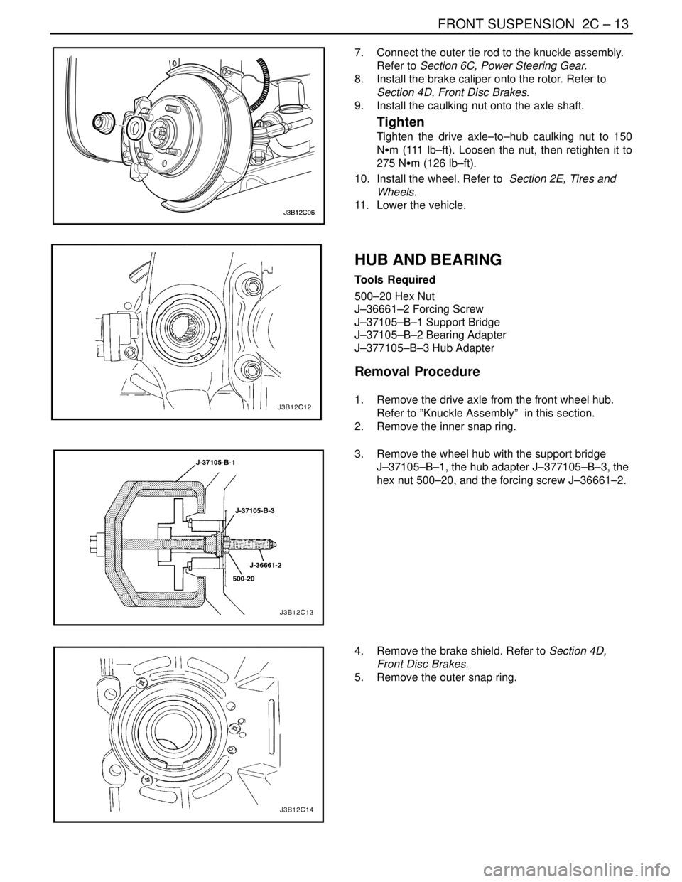
3. Remove the wheel hub with the support bridge
J–37105–B–1, the hub adapter J–377105–B–3, the
hex nut 500–20, and the forcing screw J–36661–2.
4. Remove the brake shield. Refer to Section 4D,
Front Disc Brakes.
5. Remove the outer snap ring.
Page 931 of 2643

2C – 14IFRONT SUSPENSION
DAEWOO V–121 BL4
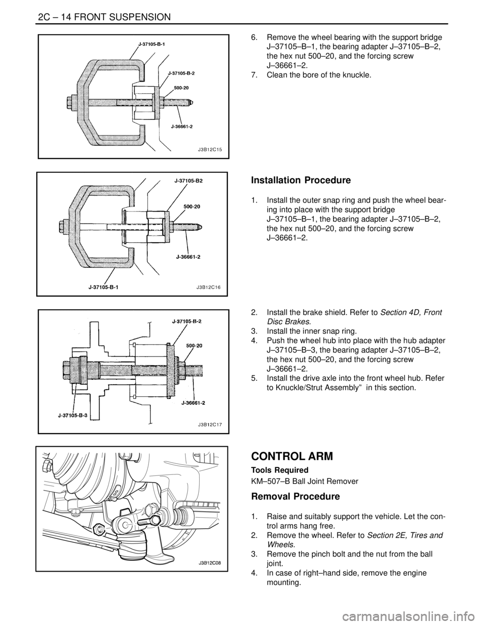
6. Remove the wheel bearing with the support bridge
J–37105–B–1, the bearing adapter J–37105–B–2,
the hex nut 500–20, and the forcing screw
J–36661–2.
7. Clean the bore of the knuckle.
Installation Procedure
1. Install the outer snap ring and push the wheel bear-
ing into place with the support bridge
J–37105–B–1, the bearing adapter J–37105–B–2,
the hex nut 500–20, and the forcing screw
J–36661–2.
2. Install the brake shield. Refer to Section 4D, Front
Disc Brakes.
3. Install the inner snap ring.
4. Push the wheel hub into place with the hub adapter
J–37105–B–3, the bearing adapter J–37105–B–2,
the hex nut 500–20, and the forcing screw
J–36661–2.
5. Install the drive axle into the front wheel hub. Refer
to Knuckle/Strut Assembly” in this section.
CONTROL ARM
Tools Required
KM–507–B Ball Joint Remover
Removal Procedure
1. Raise and suitably support the vehicle. Let the con-
trol arms hang free.
2. Remove the wheel. Refer to Section 2E, Tires and
Wheels.
3. Remove the pinch bolt and the nut from the ball
joint.
4. In case of right–hand side, remove the engine
mounting.
Page 933 of 2643

2C – 16IFRONT SUSPENSION
DAEWOO V–121 BL4
5. Install the control arm–to–crossmember bolts.
Tighten
S Tighten the front control arm–to–crossmember
bolt to 125 NSm (92 lb–ft).
S Tighten the rear control arm–to–crossmember
bolt to 110 NSm (81 lb–ft).
6. Install the wheel. Refer to Section 2E, Tires and
Wheels.
7. Lower the vehicle.
STRUT ASSEMBLY
Removal Procedure
1. Remove the strut upper cap and nut.
2. Raise and suitably support the vehicle.
3. Remove the wheel. Refer to Section 2E, Tires and
Wheels.
4. On vehicles equipped with an antilock braking sys-
tem (ABS), disconnect the ABS sensor line from
the strut assembly.
5. Remove the brake line from the securing bracket
on the strut assembly.
6. Disconnect the stabilizer shaft link by removing the
stabilizer link–to–strut assembly nut.