2004 DAEWOO LACETTI glove box
[x] Cancel search: glove boxPage 2326 of 2643

INSTRUMENTATION/DRIVER INFORMATION 9E – 27
DAEWOO V–121 BL4
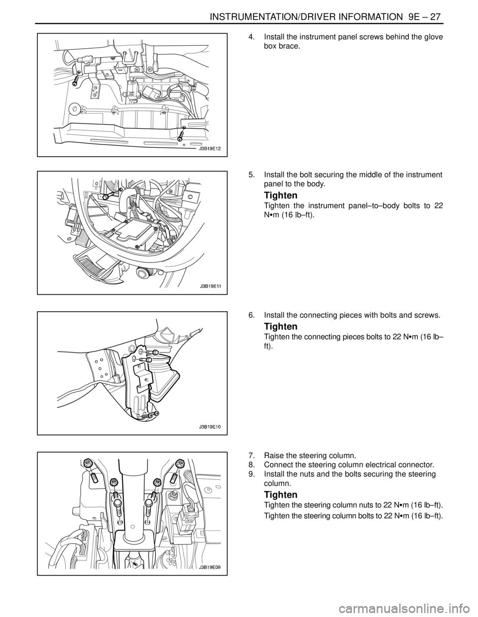
4. Install the instrument panel screws behind the glove
box brace.
5. Install the bolt securing the middle of the instrument
panel to the body.
Tighten
Tighten the instrument panel–to–body bolts to 22
NSm (16 lb–ft).
6. Install the connecting pieces with bolts and screws.
Tighten
Tighten the connecting pieces bolts to 22 NSm (16 lb–
ft).
7. Raise the steering column.
8. Connect the steering column electrical connector.
9. Install the nuts and the bolts securing the steering
column.
Tighten
Tighten the steering column nuts to 22 NSm (16 lb–ft).
Tighten the steering column bolts to 22 NSm (16 lb–ft).
Page 2327 of 2643

9E – 28IINSTRUMENTATION/DRIVER INFORMATION
DAEWOO V–121 BL4
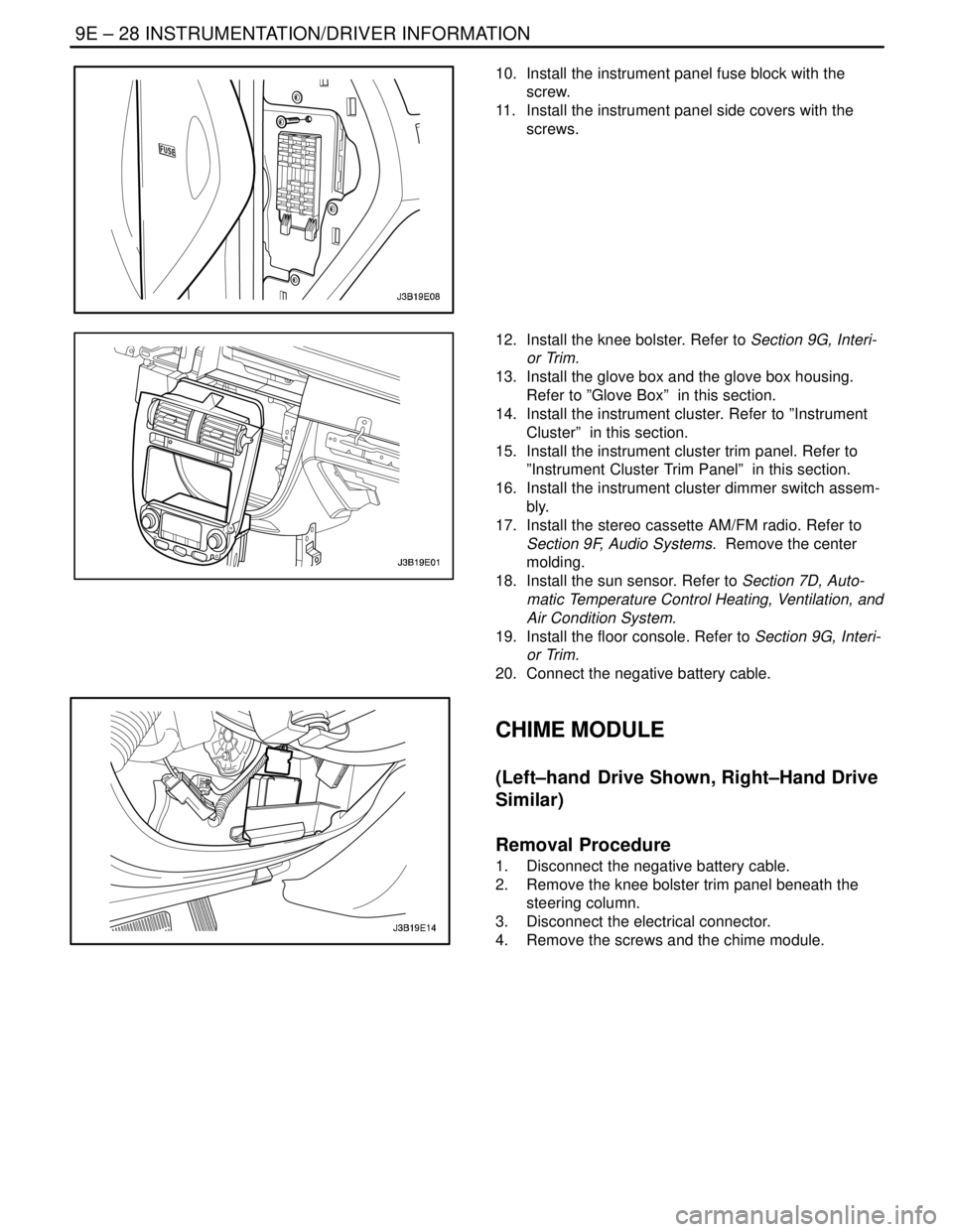
10. Install the instrument panel fuse block with the
screw.
11. Install the instrument panel side covers with the
screws.
12. Install the knee bolster. Refer to Section 9G, Interi-
or Trim.
13. Install the glove box and the glove box housing.
Refer to ”Glove Box” in this section.
14. Install the instrument cluster. Refer to ”Instrument
Cluster” in this section.
15. Install the instrument cluster trim panel. Refer to
”Instrument Cluster Trim Panel” in this section.
16. Install the instrument cluster dimmer switch assem-
bly.
17. Install the stereo cassette AM/FM radio. Refer to
Section 9F, Audio Systems. Remove the center
molding.
18. Install the sun sensor. Refer to Section 7D, Auto-
matic Temperature Control Heating, Ventilation, and
Air Condition System.
19. Install the floor console. Refer to Section 9G, Interi-
or Trim.
20. Connect the negative battery cable.
CHIME MODULE
(Left–hand Drive Shown, Right–Hand Drive
Similar)
Removal Procedure
1. Disconnect the negative battery cable.
2. Remove the knee bolster trim panel beneath the
steering column.
3. Disconnect the electrical connector.
4. Remove the screws and the chime module.
Page 2329 of 2643

9E – 30IINSTRUMENTATION/DRIVER INFORMATION
DAEWOO V–121 BL4
GENERAL DESCRIPTION
AND SYSTEM OPERATION
CIGAR LIGHTER
The cigar lighter is located in the front portion of the floor
console. To use the lighter, push it in completely. When the
lighter is hot, it will release itself from contact with the heat-
ing element. The lighter and the heating element can be
damaged if the lighter is not allowed to release itself fully
from the heating element.
ASHTRAY
The ashtray is located below the audio system. To access
the ashtray, pull it out from the center console. The ashtray
lamp will go on when the parking lamps or the headlamps
are turned on.
INSTRUMENT PANEL VENTS
The center and the side vents in the instrument panel can
be adjusted up and down and from side to side. The side
vents can also be aimed toward the side windows in order
to defog them.
GLOVE BOX
The glove box can be opened by pulling up on the latch
handle. The glove box must be removed in order to gain
access to the passenger’s side airbag module.
DIGTAL CLOCK
The digital clock is located in the instrument panel, above
the audio system. The clock is capable of a 12–hour or a
24–hour display.
INSTRUMENT CLUSTER
The instrument cluster is located above the steering col-
umn and in the instrument cluster trim panel. The instru-
ment cluster contains the instruments that provide the
driver with vehicle performance information. The instru-
ment cluster contains a speedometer, an odometer, a trip
odometer, a temperature gauge, a fuel gauge, and several
indicator lamps. For replacement of the indicator lamp
bulbs contained in the instrument cluster, refer to ”Instru-
ment Cluster Indicator Lamps Specifications” and”Instru-
ment Cluster Indicator Lamps” in this section.
SPEEDOMETER/ODOMETER/TRIP
ODOMETER
The speedometer measures the speed of the vehicle in
km/h (mph in some countries). It consists of an instrument
cluster gauge connected to the vehicle speed sensor
(VSS) on the transaxle output shaft.The odometer measures in kilometers (miles in some
countries) the total distance the vehicle has traveled since
it was manufactured. It consists of an instrument cluster
gauge connected to the VSS on the transaxle output shaft.
The trip odometer measures the distance the vehicle has
traveled since the odometer was last reset. It consists of
an instrument cluster gauge connected to the VSS on the
transaxle output shaft. The trip odometer can be reset to
zero at any time so that the driver can record the distance
traveled from any starting point.
FUEL GAUGE
The fuel gauge consists of an instrument cluster gauge
connected to a sending unit in the fuel tank.
The fuel gauge indicates the quantity of fuel in the tank
only when the ignition switch is turned to ON or ACC.
When the ignition is turned to LOCK or START, the pointer
may come to rest at any position.
TEMPERATURE GAUGE
The temperature gauge consists of an instrument cluster
gauge connected to a temperature sensor that is in con-
tact with the circulating engine coolant.
The temperature gauge indicates the temperature of the
coolant. Prolonged driving or idling in very hot weather
may cause the pointer to move beyond the center of the
gauge. The engine is overheating if the pointer moves into
the red zone at the upper limit of the gauge.
INSTRUMENT CLUSTER INDICATOR
LAMPS
The instrument cluster contains indicator lamps that indi-
cate the functioning of certain systems or the existence of
potential problems with the operation of the vehicle. The
indicator lamps are replaceable. For replacement of the in-
dicator lamps contained in the instrument cluster, refer to
”Instrument Cluster Indicator Lamps Specifications”
and”Instrument Cluster Indicator Lamps” in this section.
CHIME MODULE
The chime module is located above the instrument panel
fuse block and will sound in order to bring attention to one
or more of the following conditions:
S The lamps are on, the door is ajar, and the ignition
switch is not in ACC, ON, or START.
S The seat belt is unbuckled when the ignition switch
is in ON or START.
S The door is open when the ignition switch is in ON
or START.
S The key is left in the ignition switch when the igni-
tion is in LOCK and the door is open.
Page 2340 of 2643

AUDIO SYSTEMS 9F – 11
DAEWOO V–121 BL4
GENERAL DESCRIPTION
AND SYSTEM OPERATION
STEREO CASSETTE AM/FM RADIO
There are three audio systems offered. The stereo digital
logic cassette AM/FM radio with electronic tape ejection
is offered in standard and deluxe models. Both models
feature RDS (radio data system) which automatically se-
lects the best station within the chain of RDS stations cur-
rently being listened to. A trunk mounted CD changer is
also available.
AUDIO SCURITY SYSTEM
The audio security system is activated whenever the audio
system circuit is disconnected from the battery. A four–
digit security code must be entered in order for the audio
system to resume functioning. The security code is
stamped on a card located in the vehicle (usually in the
glove box). The following security code entering proce-
dure must be used to deactivate the audio security sys-
tem:
1. After connecting the audio security system to the
battery, ”CODE” will flash on the display.
2. Enter the proper security number into the unit, us-
ing the preset buttons No. 1 through 8.
3. For example, if the security number is ”1234”:
a. Press the preset button No. 1. ”CODE” will
disappear and ”1 – – – ” will appear on the dis-
play.
b. Press the preset button No. 2, and ”12 – – ”
will appear.
c. Press the preset button No. 3, and ”123– ” will
appear.
d. Press the preset button No. 4, and ”1234” will
appear and flash three times.4. The audio system will function and will transfer to
the radio.
If the incorrect security number is entered into the unit,
”Err” will appear followed by ”CODE” and there will be sev-
eral audible beeps. If this happens, repeat the security en-
tering procedure beginning with Step 2.
SPEAKERS
All audio systems use eight speakers, four speakers and
four tweeters mounted in each door.
TAPE PLAYER AND CASSETTE
CARE
The head and the capstan are the two parts of the tape
player that should be cleaned. This service should be per-
formed every 100 hours of cassette operation.
To clean the head and the capstan, use a cotton swab
dipped in rubbing alcohol.
A cassette cleaning kit may also be used to clean the head
and the capstan. Follow the cleaning kit instructions to
clean the tape player.
Do not touch the tape head with magnetized tools. If the
head becomes magnetized, it will degrade cassettes
played in the player. No service is performed on the cas-
settes. The cassette manufacturer handles warranties of
the cassettes. Store cassettes away from extreme heat
and direct sunlight.
COMPACT DISC CARE
Handle discs carefully. Store the discs in protective cases
away from the sun, heat, and dust. If the surface is soiled,
dampen a clean, soft cloth in a solution of mild neutral de-
tergent and wipe the disc clean.
Page 2350 of 2643

9G – 10IINTERIOR TRIM
DAEWOO V–121 BL4
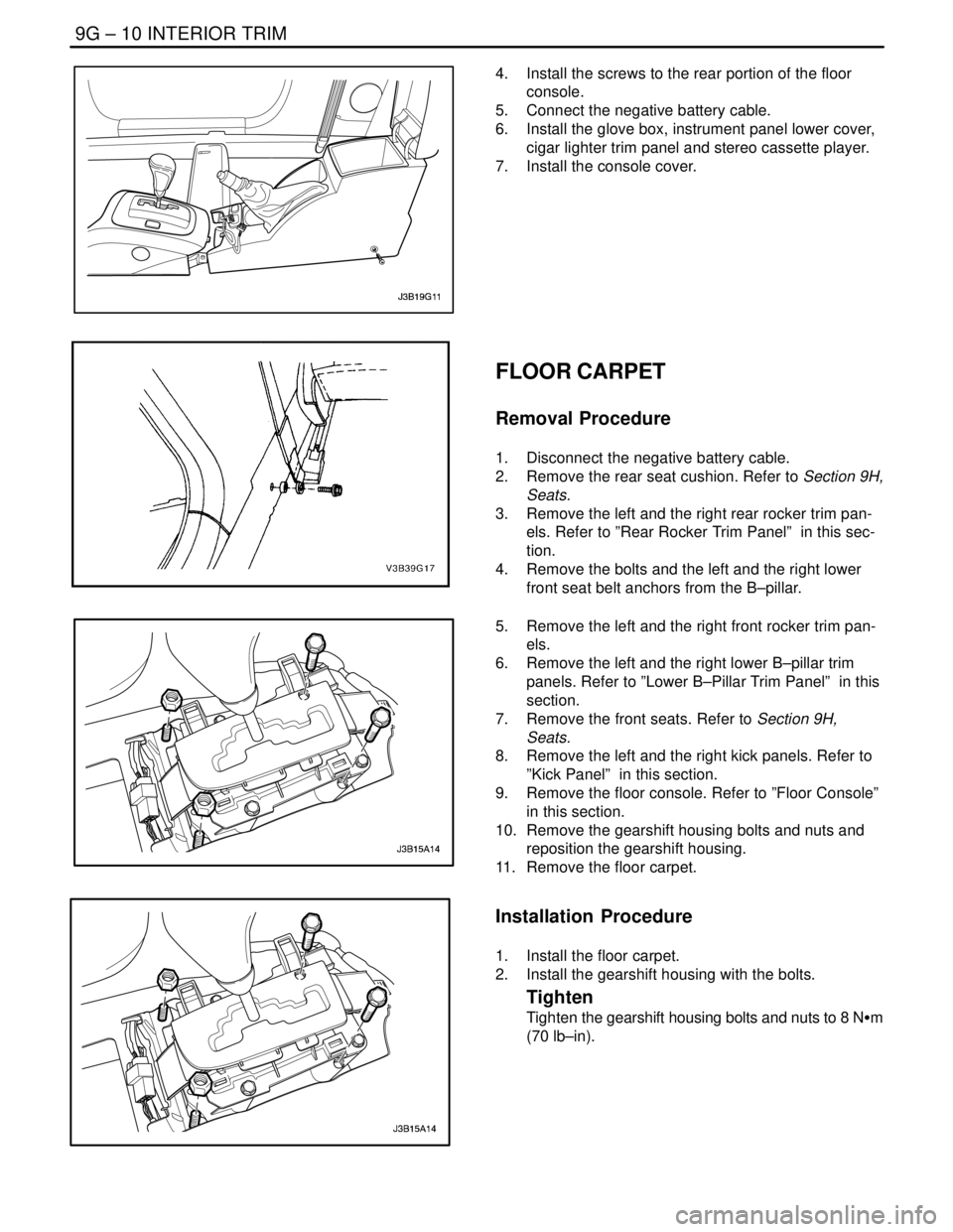
4. Install the screws to the rear portion of the floor
console.
5. Connect the negative battery cable.
6. Install the glove box, instrument panel lower cover,
cigar lighter trim panel and stereo cassette player.
7. Install the console cover.
FLOOR CARPET
Removal Procedure
1. Disconnect the negative battery cable.
2. Remove the rear seat cushion. Refer to Section 9H,
Seats.
3. Remove the left and the right rear rocker trim pan-
els. Refer to ”Rear Rocker Trim Panel” in this sec-
tion.
4. Remove the bolts and the left and the right lower
front seat belt anchors from the B–pillar.
5. Remove the left and the right front rocker trim pan-
els.
6. Remove the left and the right lower B–pillar trim
panels. Refer to ”Lower B–Pillar Trim Panel” in this
section.
7. Remove the front seats. Refer to Section 9H,
Seats.
8. Remove the left and the right kick panels. Refer to
”Kick Panel” in this section.
9. Remove the floor console. Refer to ”Floor Console”
in this section.
10. Remove the gearshift housing bolts and nuts and
reposition the gearshift housing.
11. Remove the floor carpet.
Installation Procedure
1. Install the floor carpet.
2. Install the gearshift housing with the bolts.
Tighten
Tighten the gearshift housing bolts and nuts to 8 NSm
(70 lb–in).