Page 1304 of 2643
5–144WELECTRICAL WIRING DIAGRAMS
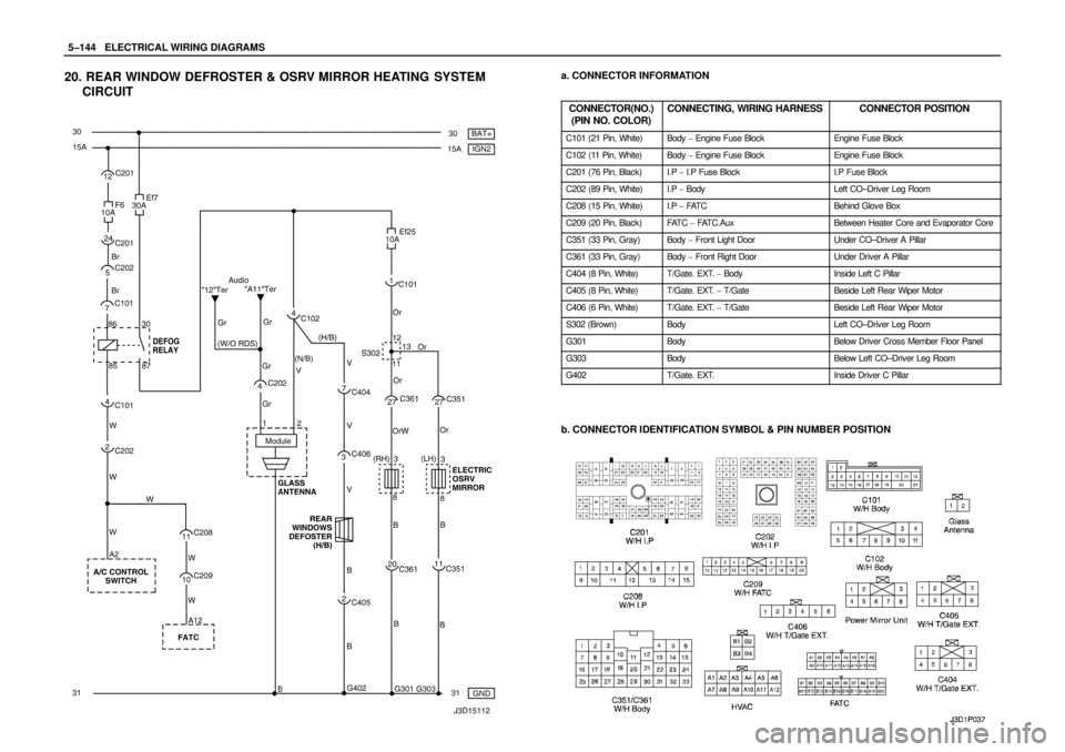
20. REAR WINDOW DEFROSTER & OSRV MIRROR HEATING SYSTEM
CIRCUITa. CONNECTOR INFORMATION
CONNECTOR(NO.)
(PIN NO. COLOR)
CONNECTING, WIRING HARNESSCONNECTOR POSITION
C101 (21 Pin, White)Body � Engine Fuse BlockEngine Fuse Block
C102 (11 Pin, White)Body � Engine Fuse BlockEngine Fuse Block
C201 (76 Pin, Black)I.P � I.P Fuse BlockI.P Fuse Block
C202 (89 Pin, White)I.P � BodyLeft CO–Driver Leg Room
C208 (15 Pin, White)I.P � FAT CBehind Glove Box
C209 (20 Pin, Black)FAT C � FAT C . A u xBetween Heater Core and Evaporator Core
C351 (33 Pin, Gray)Body � Front Light DoorUnder CO–Driver A Pillar
C361 (33 Pin, Gray)Body � Front Right DoorUnder Driver A Pillar
C404 (8 Pin, White)T/Gate. EXT. � BodyInside Left C Pillar
C405 (8 Pin, White)T/Gate. EXT. � T/GateBeside Left Rear Wiper Motor
C406 (6 Pin, White)T/Gate. EXT. � T/GateBeside Left Rear Wiper Motor
S302 (Brown)BodyLeft CO–Driver Leg Room
G301BodyBelow Driver Cross Member Floor Panel
G303BodyBelow Left CO–Driver Leg Room
G402T/Gate. EXT.Inside Driver C Pillar
b. CONNECTOR IDENTIFICATION SYMBOL & PIN NUMBER POSITION
Page 1938 of 2643
POWER STEERING GEAR 6C – 21
DAEWOO V–121 BL4
6. Fill the fluid reservoir with power steering fluid.
7. Inspect for leaks. If there are leaks, correct the
cause of the leaks and bleed the system. Refer to
”Bleeding the Power Steering System” in this sec-
tion.
SPEED SENSITIVE POWER
STEERING CONTROL MODULE
Removal Procedure
1. Disconnect negative battery cable.
2. Remove the glove box. Refer to Section 9G, Interi-
or Trim.
3. Slide the speed sensitive power steering (SSPS)
control module off from the control module bracket.
4. Disconnect the electrical connector from the SSPS
control module.
Installation Procedure
1. Connect the electrical connector to the SSPS con-
trol module.
2. Slide the SSPS control module onto the SSPS con-
trol module bracket.
3. Install the ashtray. Refer to Section 9G, Interior
Trim.
4. Connect the negative battery cable.
Page 1954 of 2643
POWER STEERING GEAR 6C – 37
DAEWOO V–121 BL4
[Vehicle Speed – Actuator Current Relation]
SOLENOID RESISTANCE
13 W
The control module is installed on the right side of the au-
dio and can be accessible after the glove box is removed.
It receives signals from the vehicle speed sensor and the
steering wheel rotation sensor and processes them to de-
cide proper fluid flow through the actuator.
It also has a self–diagnosis. If it detects any malfunction,
it starts default mode, which is basically actuator full open
for light steering effort.
TERMINALCOLORFUNCTION
1SBActuator Low
2VActuator High
3BWSteering Wheel Sensor Ground
4–Not used
5GrSteering Wheel Sensor 5V ref.
6GWVSS
7–Not Used
8PIGN ON
9BrWarning Lamp
10BWGround
11–Not Used
12–Not Used
13LDiagnosis
14SBSteering Wheel Sensor Signal
Page 1997 of 2643
HEATING AND VENTILATION SYSTEM 7A – 23
DAEWOO V–121 BL4
Tighten
Tighten the heater/air distributor case assembly
screws to 4 NSm (35 lb–in).
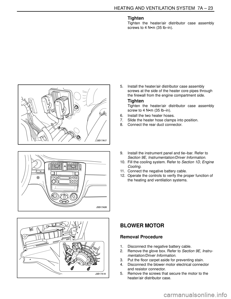
5. Install the heater/air distributor case assembly
screws at the side of the heater core pipes through
the firewall from the engine compartment side.
Tighten
Tighten the heater/air distributor case assembly
screw to 4 NSm (35 lb–in).
6. Install the two heater hoses.
7. Slide the heater hose clamps into position.
8. Connect the rear duct connector.
9. Install the instrument panel and tie–bar. Refer to
Section 9E, Instrumentation/Driver Information.
10. Fill the cooling system. Refer to Section 1D, Engine
Cooling.
11. Connect the negative battery cable.
12. Operate the controls to verify the proper function of
the heating and ventilation systems.
BLOWER MOTOR
Removal Procedure
1. Disconnect the negative battery cable.
2. Remove the glove box. Refer to Section 9E, Instru-
mentation/Driver Information.
3. Put the floor carpet aside for preventing stain.
4. Disconnect the blower motor electrical connector
and resistor connector.
5. Remove the screws that secure the motor to the
heater/air distributor case.
Page 1998 of 2643
7A – 24IHEATING AND VENTILATION SYSTEM
DAEWOO V–121 BL4
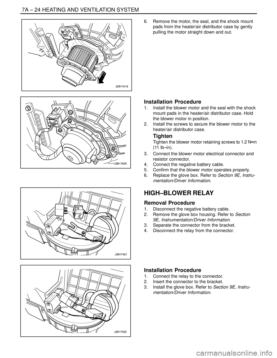
6. Remove the motor, the seal, and the shock mount
pads from the heater/air distributor case by gently
pulling the motor straight down and out.
Installation Procedure
1. Install the blower motor and the seal with the shock
mount pads in the heater/air distributor case. Hold
the blower motor in position.
2. Install the screws to secure the blower motor to the
heater/air distributor case.
Tighten
Tighten the blower motor retaining screws to 1.2 NSm
(11 lb–in).
3. Connect the blower motor electrical connector and
resistor connector.
4. Connect the negative battery cable.
5. Confirm that the blower motor operates properly.
6. Replace the glove box. Refer to Section 9E, Instru-
mentation/Driver Information.
HIGH–BLOWER RELAY
Removal Procedure
1. Disconnect the negative battery cable.
2. Remove the glove box housing. Refer to Section
9E, Instrumentation/Driver Information.
3. Separate the connector from the bracket.
4. Disconnect the relay from the connector.
Installation Procedure
1. Connect the relay to the connector.
2. Insert the connector to the bracket.
3. Install the glove box. Refer to Section 9E, Instru-
mentation/Driver Information.
Page 1999 of 2643
HEATING AND VENTILATION SYSTEM 7A – 25
DAEWOO V–121 BL4
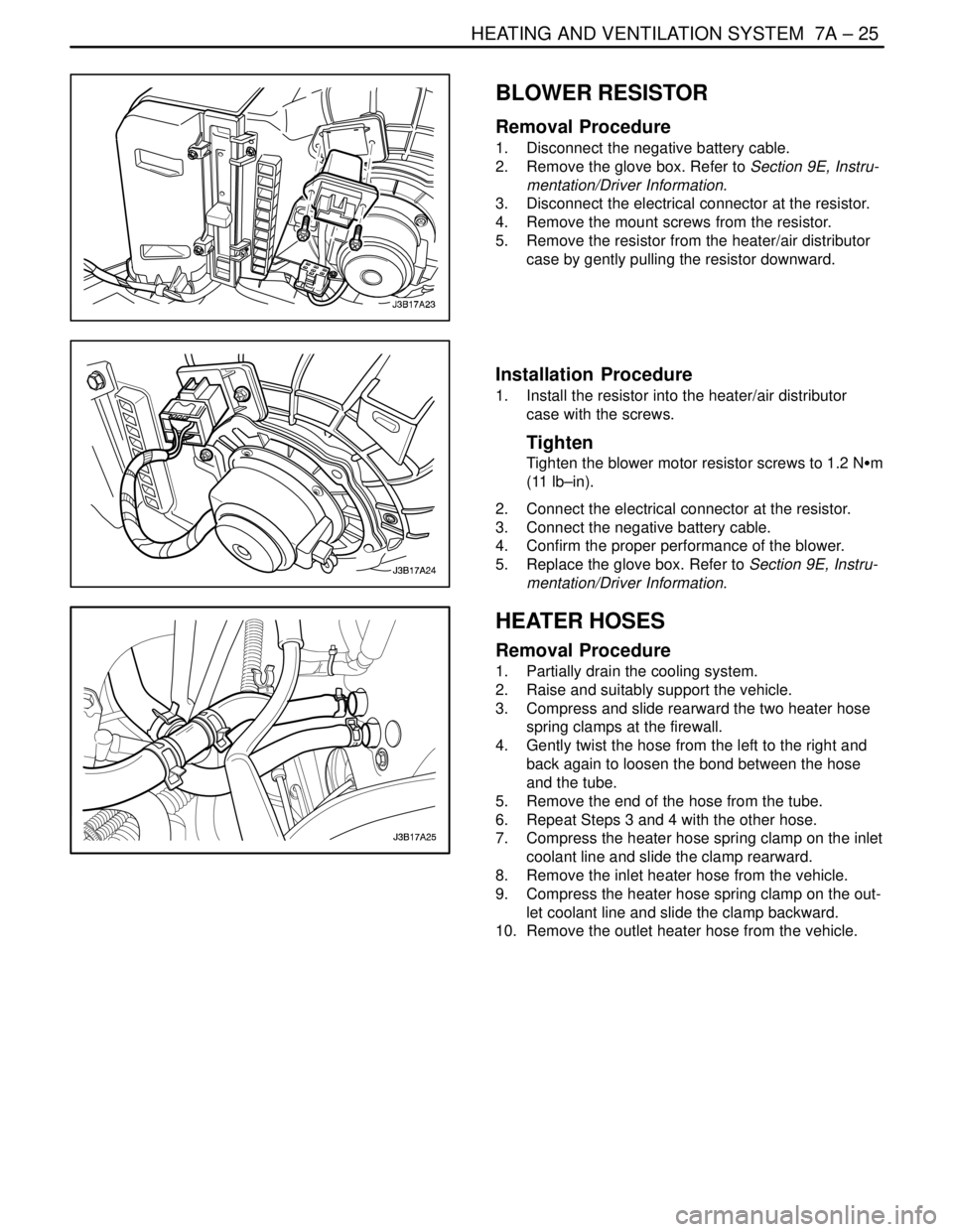
BLOWER RESISTOR
Removal Procedure
1. Disconnect the negative battery cable.
2. Remove the glove box. Refer to Section 9E, Instru-
mentation/Driver Information.
3. Disconnect the electrical connector at the resistor.
4. Remove the mount screws from the resistor.
5. Remove the resistor from the heater/air distributor
case by gently pulling the resistor downward.
Installation Procedure
1. Install the resistor into the heater/air distributor
case with the screws.
Tighten
Tighten the blower motor resistor screws to 1.2 NSm
(11 lb–in).
2. Connect the electrical connector at the resistor.
3. Connect the negative battery cable.
4. Confirm the proper performance of the blower.
5. Replace the glove box. Refer to Section 9E, Instru-
mentation/Driver Information.
HEATER HOSES
Removal Procedure
1. Partially drain the cooling system.
2. Raise and suitably support the vehicle.
3. Compress and slide rearward the two heater hose
spring clamps at the firewall.
4. Gently twist the hose from the left to the right and
back again to loosen the bond between the hose
and the tube.
5. Remove the end of the hose from the tube.
6. Repeat Steps 3 and 4 with the other hose.
7. Compress the heater hose spring clamp on the inlet
coolant line and slide the clamp rearward.
8. Remove the inlet heater hose from the vehicle.
9. Compress the heater hose spring clamp on the out-
let coolant line and slide the clamp backward.
10. Remove the outlet heater hose from the vehicle.
Page 2027 of 2643
MANUAL CONTROL HEATING, VENTILATION AND AIR CONDITIONING SYSTEM 7B – 25
DAEWOO V–121 BL4
AIR FILTER
(Left–Hand Drive Shown, Right–Hand Drive
Similar)
Removal Procedure
1. Remove the glove box. Refer to Section 9E, Instru-
mentation/Driver Information.
2. Remove the screws and the air filter.
3. Remove the air filter.
Installation Procedure
1. Install the air filter.
2. Install the air filter cover and the screws.
3. Install the glove box. Refer to Section 9E, Instru-
mentation/Driver Information.
A/C EXPANSION VALVE
(Left–Hand Drive Shown, Right–Hand Drive
Similar)
Removal Procedure
1. Disconnect the negative battery cable.
2. Recover the refrigerant. Refer to ”Discharging, Add-
ing Oil, Evacuating, and Charging Procedures for
A/C System” in this section.
3. Remove the suction hose/liquid pipe block retaining
nuts at the fire wall.
4. Remove the expansion valve connector block re-
taining stud bolts.
5. Remove the expansion valve.
6. Discard the O–rings.
Page 2089 of 2643
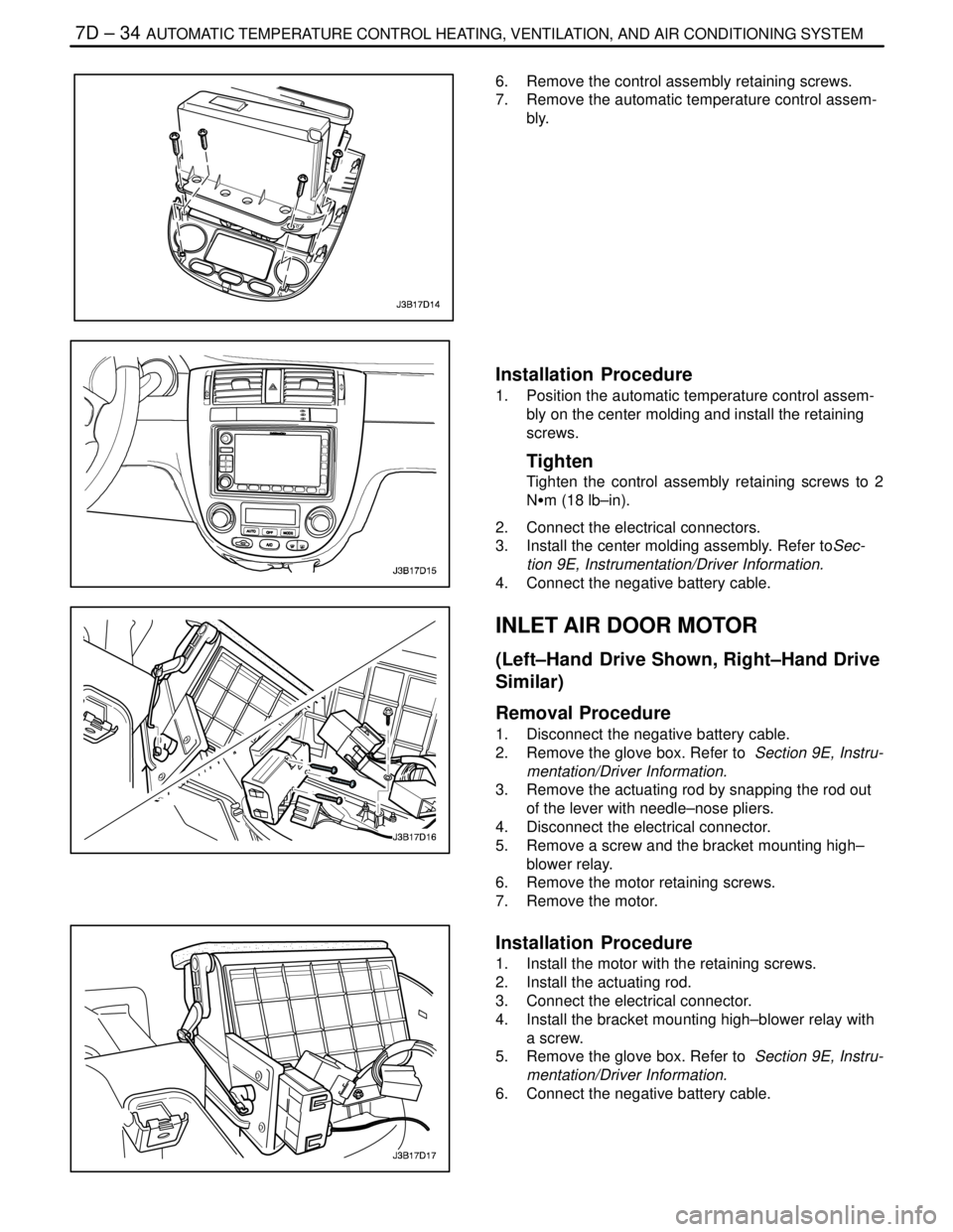
7D – 34IAUTOMATIC TEMPERATURE CONTROL HEATING, VENTILATION, AND AIR CONDITIONING SYSTEM
DAEWOO V–121 BL4
6. Remove the control assembly retaining screws.
7. Remove the automatic temperature control assem-
bly.
Installation Procedure
1. Position the automatic temperature control assem-
bly on the center molding and install the retaining
screws.
Tighten
Tighten the control assembly retaining screws to 2
NSm (18 lb–in).
2. Connect the electrical connectors.
3. Install the center molding assembly. Refer toSec-
tion 9E, Instrumentation/Driver Information.
4. Connect the negative battery cable.
INLET AIR DOOR MOTOR
(Left–Hand Drive Shown, Right–Hand Drive
Similar)
Removal Procedure
1. Disconnect the negative battery cable.
2. Remove the glove box. Refer to Section 9E, Instru-
mentation/Driver Information.
3. Remove the actuating rod by snapping the rod out
of the lever with needle–nose pliers.
4. Disconnect the electrical connector.
5. Remove a screw and the bracket mounting high–
blower relay.
6. Remove the motor retaining screws.
7. Remove the motor.
Installation Procedure
1. Install the motor with the retaining screws.
2. Install the actuating rod.
3. Connect the electrical connector.
4. Install the bracket mounting high–blower relay with
a screw.
5. Remove the glove box. Refer to Section 9E, Instru-
mentation/Driver Information.
6. Connect the negative battery cable.