2004 DAEWOO LACETTI oil temperature
[x] Cancel search: oil temperaturePage 274 of 2643
1F – 28IENGINE CONTROLS
DAEWOO V–121 BL4
COMPONENT LOCATOR
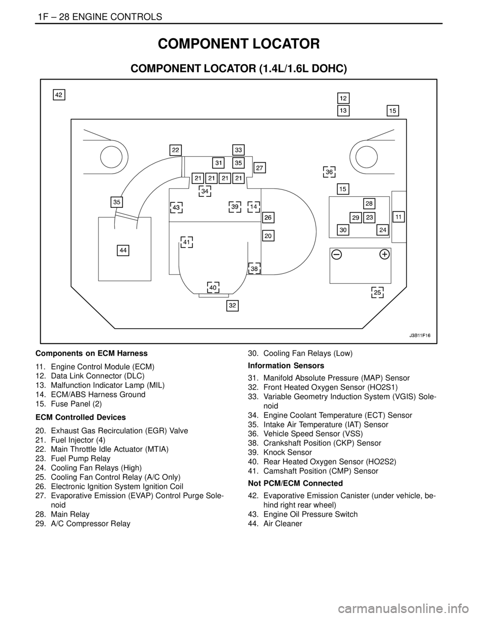
COMPONENT LOCATOR (1.4L/1.6L DOHC)
Components on ECM Harness
11. Engine Control Module (ECM)
12. Data Link Connector (DLC)
13. Malfunction Indicator Lamp (MIL)
14. ECM/ABS Harness Ground
15. Fuse Panel (2)
ECM Controlled Devices
20. Exhaust Gas Recirculation (EGR) Valve
21. Fuel Injector (4)
22. Main Throttle Idle Actuator (MTIA)
23. Fuel Pump Relay
24. Cooling Fan Relays (High)
25. Cooling Fan Control Relay (A/C Only)
26. Electronic Ignition System Ignition Coil
27. Evaporative Emission (EVAP) Control Purge Sole-
noid
28. Main Relay
29. A/C Compressor Relay30. Cooling Fan Relays (Low)
Information Sensors
31. Manifold Absolute Pressure (MAP) Sensor
32. Front Heated Oxygen Sensor (HO2S1)
33. Variable Geometry Induction System (VGIS) Sole-
noid
34. Engine Coolant Temperature (ECT) Sensor
35. Intake Air Temperature (IAT) Sensor
36. Vehicle Speed Sensor (VSS)
38. Crankshaft Position (CKP) Sensor
39. Knock Sensor
40. Rear Heated Oxygen Sensor (HO2S2)
41. Camshaft Position (CMP) Sensor
Not PCM/ECM Connected
42. Evaporative Emission Canister (under vehicle, be-
hind right rear wheel)
43. Engine Oil Pressure Switch
44. Air Cleaner
Page 275 of 2643
ENGINE CONTROLS 1F – 29
DAEWOO V–121 BL4
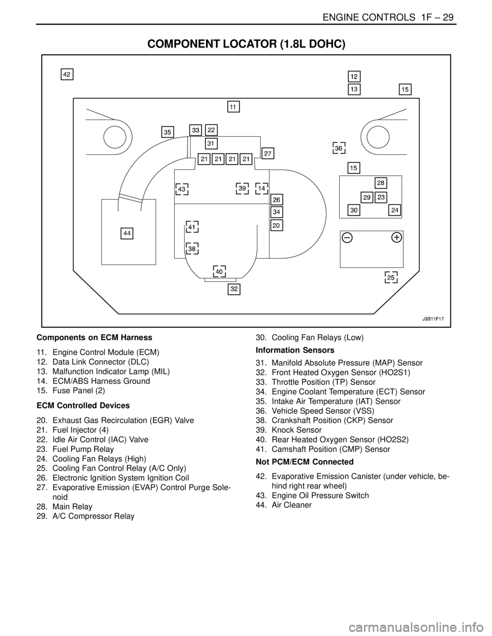
COMPONENT LOCATOR (1.8L DOHC)
Components on ECM Harness
11. Engine Control Module (ECM)
12. Data Link Connector (DLC)
13. Malfunction Indicator Lamp (MIL)
14. ECM/ABS Harness Ground
15. Fuse Panel (2)
ECM Controlled Devices
20. Exhaust Gas Recirculation (EGR) Valve
21. Fuel Injector (4)
22. Idle Air Control (IAC) Valve
23. Fuel Pump Relay
24. Cooling Fan Relays (High)
25. Cooling Fan Control Relay (A/C Only)
26. Electronic Ignition System Ignition Coil
27. Evaporative Emission (EVAP) Control Purge Sole-
noid
28. Main Relay
29. A/C Compressor Relay30. Cooling Fan Relays (Low)
Information Sensors
31. Manifold Absolute Pressure (MAP) Sensor
32. Front Heated Oxygen Sensor (HO2S1)
33. Throttle Position (TP) Sensor
34. Engine Coolant Temperature (ECT) Sensor
35. Intake Air Temperature (IAT) Sensor
36. Vehicle Speed Sensor (VSS)
38. Crankshaft Position (CKP) Sensor
39. Knock Sensor
40. Rear Heated Oxygen Sensor (HO2S2)
41. Camshaft Position (CMP) Sensor
Not PCM/ECM Connected
42. Evaporative Emission Canister (under vehicle, be-
hind right rear wheel)
43. Engine Oil Pressure Switch
44. Air Cleaner
Page 339 of 2643
ENGINE CONTROLS 1F – 93
DAEWOO V–121 BL4
ENGINE COOLING FAN CIRCUIT CHECK – DUAL FAN
(1.4L/1.6L DOHC)
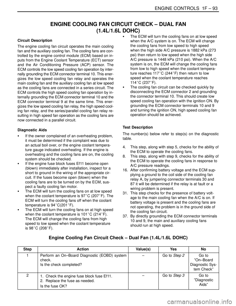
Circuit Description
The engine cooling fan circuit operates the main cooling
fan and the auxiliary cooling fan. The cooling fans are con-
trolled by the engine control module (ECM) based on in-
puts from the Engine Coolant Temperature (ECT) sensor
and the Air Conditioning Pressure (ACP) sensor. The
ECM controls the low speed cooling fan operation by inter-
nally grounding the ECM connector terminal 10. This ener-
gizes the low speed cooling fan relay and operates the
main cooling fan and the auxiliary cooling fan at low speed
as the cooling fans are connected in a series circuit. The
ECM controls the high speed cooling fan operation by in-
ternally grounding the ECM connector terminal 10 and the
ECM connector terminal 9 at the same time. This ener-
gizes the low speed cooling fan relay, the high speed cool-
ing fan relay, and the series/parallel cooling fan relay re-
sulting in high speed fan operation as the cooling fans are
now connected in a parallel circuit.
Diagnostic Aids
S If the owner complained of an overheating problem,
it must be determined if the complaint was due to
an actual boil over, or the engine coolant tempera-
ture gauge indicated overheating. If the engine is
overheating and the cooling fans are on, the cooling
system should be checked.
S If the engine fuse block fuses Ef11 become open
(blown) immediately after installation, inspect for a
short to ground in the wiring of the appropriate cir-
cuit. If the fuses become open (blown) when the
cooling fans are to be turned on by the ECM, sus-
pect a faulty cooling fan motor.
S The ECM will turn the cooling fans on at low speed
when the coolant temperature is 97°C (207°F). The
ECM will turn the cooling fans off when the coolant
temperature is 94°C(201°F).
S The ECM will turn the cooling fans on at high speed
when the coolant temperature is 101°C (214°F).
The ECM will change the cooling fans from high
speed to low speed when the coolant temperature
is 98°C (208°F).S The ECM will turn the cooling fans on at low speed
when the A/C system is on. The ECM will change
the cooling fans from low speed to high speed
when the high side A/C pressure is 1882 kPa (273
psi) then return to low speed when the high side
A/C pressure is 1448 kPa (210 psi). When the A/C
system is on, the ECM will change the cooling fans
from low to high speed when the coolant tempera-
ture reaches 117°C (244°F) then return to low
speed when the coolant temperature reaches
11 4°C (237°F).
S The cooling fan circuit can be checked quickly by
disconnecting the ECM connector 2 and grounding
the connector terminal 10. This should create low
speed cooling fan operation with the ignition ON. By
grounding the ECM connector terminals 10 and 9
and turning the ignition ON, high speed cooling fan
operation should be achieved.
Test Description
The number(s) below refer to step(s) on the diagnostic
table.
4. This step, along with step 5, checks for the ability of
the ECM to operate the cooling fans.
8. This step, along with step 9, checks for the ability of
the ECM to operate the cooling fans in response to
A/C pressure readings.
16. After confirming battery voltage and the ECM sup-
plying a ground to the coil side of the cooling fan
relay A, by jumpering connector terminals 30 and
87 it will be determined if the relay is at fault or a
wiring problem is present.
31. This step checks for the presence of battery volt-
age to the main cooling fan when the A/C is on. If
battery voltage is present and the cooling fans are
not operating, the problem is in the ground side of
the cooling fan circuit.
37. By directly grounding the ECM connector terminals
10 and 9, the main and auxiliary cooling fans
should run at high speed.
Engine Cooling Fan Circuit Check – Dual Fan (1.4L/1.6L DOHC)
StepActionValue(s)YesNo
1Perform an On–Board Diagnostic (EOBD) system
check.
Is the check completed?–Go to Step 2Go to
”On–Board
Diagnostic Sys-
tem Check”
21. Check the engine fuse block fuse Ef11.
2. Replace the fuse as needed.
Is the fuse OK?–Go to Step 3Go to
”Diagnostic
Aids”
Page 346 of 2643
1F – 100IENGINE CONTROLS
DAEWOO V–121 BL4
ENGINE COOLING FAN CIRCUIT CHECK – DUAL FAN
(1.8L DOHC)
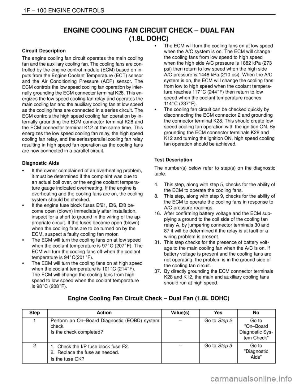
Circuit Description
The engine cooling fan circuit operates the main cooling
fan and the auxiliary cooling fan. The cooling fans are con-
trolled by the engine control module (ECM) based on in-
puts from the Engine Coolant Temperature (ECT) sensor
and the Air Conditioning Pressure (ACP) sensor. The
ECM controls the low speed cooling fan operation by inter-
nally grounding the ECM connector terminal K28. This en-
ergizes the low speed cooling fan relay and operates the
main cooling fan and the auxiliary cooling fan at low speed
as the cooling fans are connected in a series circuit. The
ECM controls the high speed cooling fan operation by in-
ternally grounding the ECM connector terminal K28 and
the ECM connector terminal K12 at the same time. This
energizes the low speed cooling fan relay, the high speed
cooling fan relay, and the series/parallel cooling fan relay
resulting in high speed fan operation as the cooling fans
are now connected in a parallel circuit.
Diagnostic Aids
S If the owner complained of an overheating problem,
it must be determined if the complaint was due to
an actual boil over, or the engine coolant tempera-
ture gauge indicated overheating. If the engine is
overheating and the cooling fans are on, the cooling
system should be checked.
S If the engine fuse block fuses Ef21, Ef6, Ef8 be-
come open (blown) immediately after installation,
inspect for a short to ground in the wiring of the ap-
propriate circuit. If the fuses become open (blown)
when the cooling fans are to be turned on by the
ECM, suspect a faulty cooling fan motor.
S The ECM will turn the cooling fans on at low speed
when the coolant temperature is 97°C (207°F). The
ECM will turn the cooling fans off when the coolant
temperature is 94°C(201°F).
S The ECM will turn the cooling fans on at high speed
when the coolant temperature is 101°C (214°F).
The ECM will change the cooling fans from high
speed to low speed when the coolant temperature
is 98°C (208°F).S The ECM will turn the cooling fans on at low speed
when the A/C system is on. The ECM will change
the cooling fans from low speed to high speed
when the high side A/C pressure is 1882 kPa (273
psi) then return to low speed when the high side
A/C pressure is 1448 kPa (210 psi). When the A/C
system is on, the ECM will change the cooling fans
from low to high speed when the coolant tempera-
ture reaches 117°C (244°F) then return to low
speed when the coolant temperature reaches
11 4°C (237°F).
S The cooling fan circuit can be checked quickly by
disconnecting the ECM connector 2 and grounding
the connector terminal K28. This should create low
speed cooling fan operation with the ignition ON. By
grounding the ECM connector terminals K28 and
K12 and turning the ignition ON, high speed cooling
fan operation should be achieved.
Test Description
The number(s) below refer to step(s) on the diagnostic
table.
4. This step, along with step 5, checks for the ability of
the ECM to operate the cooling fans.
8. This step, along with step 9, checks for the ability of
the ECM to operate the cooling fans in response to
A/C pressure readings.
16. After confirming battery voltage and the ECM sup-
plying a ground to the coil side of the cooling fan
relay A, by jumpering connector terminals 30 and
87 it will be determined if the relay is at fault or a
wiring problem is present.
31. This step checks for the presence of battery volt-
age to the main cooling fan when the A/C is on. If
battery voltage is present and the cooling fans are
not operating, the problem is in the ground side of
the cooling fan circuit.
37. By directly grounding the ECM connector terminals
K28 and K12, the main and auxiliary cooling fans
should run at high speed.
Engine Cooling Fan Circuit Check – Dual Fan (1.8L DOHC)
StepActionValue(s)YesNo
1Perform an On–Board Diagnostic (EOBD) system
check.
Is the check completed?–Go to Step 2Go to
”On–Board
Diagnostic Sys-
tem Check”
21. Check the I/P fuse block fuse F2.
2. Replace the fuse as needed.
Is the fuse OK?–Go to Step 3Go to
”Diagnostic
Aids”
Page 436 of 2643

1F – 190IENGINE CONTROLS
DAEWOO V–121 BL4
StepNo Yes Value(s) Action
19Repair the open ignition feed circuit between the fuel
injector harness connector and the fuel injector con-
nector.
Is the repair complete?–Go to Step 27–
20Measure the resistance of the spark plug cable that
the spark plug tester did not spark.
Is the resistance of the spark plug cable less than the
specified value?30000WGo to Step 21Go to Step 25
21Inspect the Engine Control Module (ECM) connec-
tor and connections.
Are the connections OK?–Go to Step 22Go to Step 23
22Check the affected cylinders ignition control circuit
for an open or short and repair as necessary.
Is the repair complete?–Go to Step 27Go to Step 26
23Repair the connector or connections.
Is the repair complete?–Go to Step 27–
241. Turn the ignition OFF.
2. Replace the ECM.
Is the repair complete?–Go to Step 27–
25Replace the spark plug cable.
Is the repair complete?–Go to Step 27–
26Replace the faulty ignition coil.
Is the repair complete?–Go to Step 27Go to Step 24
271. Using the scan tool, clear the DTCs.
2. Start the engine and idle at normal operating
temperature.
3. Operate the vehicle within the conditions for
setting this DTC as supported in the text.
Does the scan tool indicate that this diagnostic ran
and passed?–Go to Step 28Go to Step 2
28Check if any additional DTCs are set.
Are any DTCs displayed that have not been diag-
nosed?–Go to
Applicable DTC
tableSystem OK
Page 440 of 2643

1F – 194IENGINE CONTROLS
DAEWOO V–121 BL4
StepNo Yes Value(s) Action
19Repair the open ignition feed circuit between the fuel
injector harness connector and the fuel injector con-
nector.
Is the repair complete?–Go to Step 27–
20Measure the resistance of the spark plug cable that
the spark plug tester did not spark.
Is the resistance of the spark plug cable less than the
specified value?30000WGo to Step 21Go to Step 25
21Inspect the Engine Control Module (ECM) connec-
tor and connections.
Are the connections OK?–Go to Step 22Go to Step 23
22Check the affected cylinders ignition control circuit
for an open or short and repair as necessary.
Is the repair complete?–Go to Step 27Go to Step 26
23Repair the connector or connections.
Is the repair complete?–Go to Step 27–
241. Turn the ignition OFF.
2. Replace the ECM.
Is the repair complete?–Go to Step 27–
25Replace the spark plug cable.
Is the repair complete?–Go to Step 27–
26Replace the faulty ignition coil.
Is the repair complete?–Go to Step 27Go to Step 24
271. Using the scan tool, clear the DTCs.
2. Start the engine and idle at normal operating
temperature.
3. Operate the vehicle within the conditions for
setting this DTC as supported in the text.
Does the scan tool indicate that this diagnostic ran
and passed?–Go to Step 28Go to Step 2
28Check if any additional DTCs are set.
Are any DTCs displayed that have not been diag-
nosed?–Go to
Applicable DTC
tableSystem OK
Page 461 of 2643

ENGINE CONTROLS 1F – 215
DAEWOO V–121 BL4
DTC P0351 – Ignition Signal Coil A Fault
StepActionValue(s)YesNo
1Perform an Euro On–Board Diagnostic (EOBD)
System Check.
Is the system check complete?–Go to Step 2Go to
”On–Board
Diagnostic Sys-
tem Check”
2Check for a faulty connection or a damaged terminal
A at the ignition coil.
Is a problem found?–Go to Step 8Go to Step 3
3Check for a faulty connection or a damaged terminal
32 at the engine control module(ECM) connector.
Is the problem found?–Go to Step 8Go to Step 4
41. Turn the ignition switch to LOCK.
2. Disconnect the ECM.
3. Check the ignition control circuit for a short to
ground.
Is the problem found?–Go to Step 8Go to Step 5
5Check the ignition control circuit for a short to battery
voltage.
Is the problem found?–Go to Step 8Go to Step 6
6Check for an open in the ignition control.
Is the problem found?–Go to Step 8Go to Step 7
7Replace the ECM.
Is the replacement complete?–Go to Step 8–
81. Using the scan tool, clear the Diagnostic
Trouble Codes(DTCs).
S Start the engine and Idle at normal operat-
ing temperature.
S Operate the vehicle within the conditions
for setting this DTC as specified in the sup-
porting text.
Does the scan tool indicate that this diagnostic ran
and passed?–Go to Step 9–
9Check if any additional DTCs are set.
Are any DTCs displayed that have not been diag-
nosed?–Go to
Applicable DTC
tableSystem OK
Page 463 of 2643

ENGINE CONTROLS 1F – 217
DAEWOO V–121 BL4
DTC P0352 – Ignition Signal Coil B Fault
StepActionValue(s)YesNo
1Perform an Euro On–Board Diagnostic (EOBD)
System Check.
Is the system check complete?–Go to Step 2Go to
”On–Board
Diagnostic Sys-
tem Check”
2Check for a faulty connection or a damaged terminal
C at the ignition coil.
Is a problem found?–Go to Step 8Go to Step 3
3Check for a faulty connection or a damaged terminal
31 at the engine control module(ECM) connector.
Is the problem found?–Go to Step 8Go to Step 4
41. Turn the ignition switch to LOCK.
2. Disconnect the ECM.
3. Check the ignition control circuit for a short to
ground.
Is the problem found?–Go to Step 8Go to Step 5
5Check the ignition control circuit for a short to battery
voltage.
Is the problem found?–Go to Step 8Go to Step 6
6Check for an open in the ignition control.
Is the problem found?–Go to Step 8Go to Step 7
7Replace the ECM.
Is the replacement complete?–Go to Step 8–
81. Using the scan tool, clear the Diagnostic
Trouble Codes(DTCs).
S Start the engine and Idle at normal operat-
ing temperature.
S Operate the vehicle within the conditions
for setting this DTC as specified in the sup-
porting text.
Does the scan tool indicate that this diagnostic ran
and passed?–Go to Step 9–
9Check if any additional DTCs are set.
Are any DTCs displayed that have not been diag-
nosed?–Go to
Applicable DTC
tableSystem OK