Page 1726 of 2643
5A2 – 136IAISIN AUTOMATIC TRANSAXLE
DAEWOO V–121 BL4
WARNING : USE CAUTION WHEN REMOVING COM-
PONENTS WITH COMPRESSED AIR OR PERSONAL
INJURY MAY RESULT.
Notice : Blowing off the air may cause the piston’s jump–
out.When removing the piston, hold it with your hand using
a waste cloth.
Notice : Take care not to splash ATF when air–blowing.
93. Apply 392 kPa (57 psi) of compressed air to the
transaxle rear cover to remove the O/D brake pis-
ton.
94. Remove the 2 O–rings from the O/D brake piston.
95. Remove the 2 seal rings from the transaxle rear
cover.
Notice : Do not expand the seal ring excessively.
96. Remove the 4 screw plugs and 4 O–rings from the
transaxle rear cover.
Page 1727 of 2643
AISIN AUTOMATIC TRANSAXLE 5A2 – 137
DAEWOO V–121 BL4
MAJOR COMPONENT ASSEMBLY
Tools Required
DW240–020 Brake/Clutch Spring Compressor
DW240–050 Overdrive Brake Adapter
DW240–060–01 Brake Spring Compressor Bolt/Nut
DW240–060–02 Brake Spring Compressor Plate
DW240–070 1st / Reverse Brake Adapter
DW240–100 Counter Drive Gear Installation Adapter
DW240–130 Differential Preload Adapter
DW260–031–01 Transaxle Housing Oil Seal Installer
DW260–031–02 Transaxle Case Oil Seal Installer
DW260–041 Planetary Ring Gear Nut Removal/Installa-
tion Socket
DW240–160 Transaxle Case Outer Tapered Roller Bear-
ing Race Adapter
DW240–140 Transaxle Housing Side Bearing Outer Race
Adapter
DW240–170 Adapter Handle
Assembly Procedure
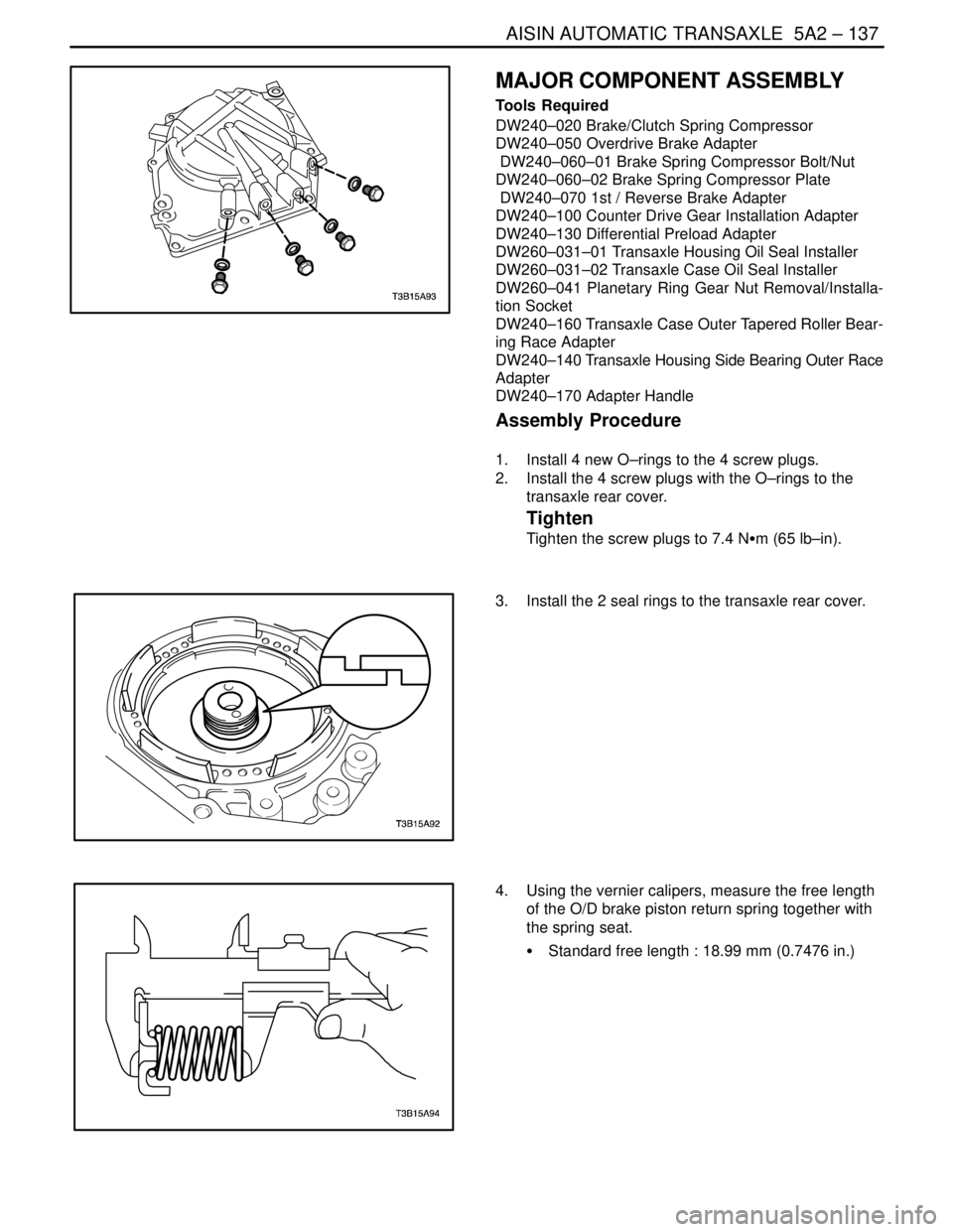
1. Install 4 new O–rings to the 4 screw plugs.
2. Install the 4 screw plugs with the O–rings to the
transaxle rear cover.
Tighten
Tighten the screw plugs to 7.4 NSm (65 lb–in).
3. Install the 2 seal rings to the transaxle rear cover.
4. Using the vernier calipers, measure the free length
of the O/D brake piston return spring together with
the spring seat.
S Standard free length : 18.99 mm (0.7476 in.)
Page 1728 of 2643
5A2 – 138IAISIN AUTOMATIC TRANSAXLE
DAEWOO V–121 BL4
5. Coat 2 new O–rings with ATF, install them to the
O/D brake piston.
6. Coat the O/D brake piston with ATF, install it to the
transaxle rear cover.
Notice : Be careful not to damage the O–rings of the O/D
brake piston.
7. Using brake/clutch spring compressor DW240–020,
overdrive brake adapter DW240–050 and a driver,
install the O/D brake return spring and snap ring to
the transaxle rear cover.
Notice : Stop the press when the O/D brake piston is low-
ered 1–2 mm (0.039 �0.078 in.) from the snap ring groove,
preventing the O/D brake piston from being deformed.
8. Using transaxle housing side bearing outer race
adapter DW240–140 and adapter handle
DW240–170, install a new side bearing outer race
into the transaxle housing.
Page 2568 of 2643

NUBIRA/LACETTI FRAME DOOR OPENING, DOOR AND SIDE PANEL OUTER 6–3
1–2. REPAIR PROCEDURE
1. Remove the related parts.
S Doors.
S Weather strips, pillar trims and related parts.
S Carpet.
S Seat belt assembly
S Door switch and wiring harness.
S Fuel pipe and brake oil pipe.
S Other related parts.
Note : Pull out and straighten the damaged area to
approximately the original shape.
2. Remove the related parts.
S Damage may extend to the inner roof frame, the inner
frame door opening and the floor. Determine the extent
of the damage first, so the frame can be pulled out prop-
erly.
Note : Use heat–resistant protective cover for protect
painting areas, seats, carpets and other parts.
S Pull out and straighten the damaged areas.
S Do not pull out more than necessary.
3. Cut and pry off the frame door opening.
S Check the damage on the frame door opening, then cut
the new frame door opening so it will overlap by
30mm(1.18in.) in the pillar, front and rear.
S Cut the damaged area with a hand saw along the bold
line as shown.
Note : Be careful not to cut the inner panel. This could
result in extensive repair.
Fig. 2
S If the damage involves part of the center pillar, cut them
as shown.
Fig. 3
S Center punch around the spot weld imprints on the
welded flange.
S Use the special spot cutter to drill holes at the spot weld
nuggets.
Note : When drilling holes be careful not to drill down to
the inner panel..
S Pry off the frame door opening panel with an air chisel,
leaving the welding flanges intact.
CAUTION : To prevent eye injury, wear goggles or
safety glasses whenever sanding, cutting, or grind-
ing.
4. Mold damaged related parts.
S Fill any holes drilled by welding.
CAUTION : To prevent eye injury and burns when
welding, wear an approved welding helmet, gloves
and safety shoes.
S Use a hammer and dolly to mold damaged areas of the
remaining inner panel and even out the welding flanges.
S Level and finish the burrs from the pried off spot welds
with disc sander.
S Sand off the paint and undercoat from both sides of the
flange to be welded.
5. Set the new frame door opening.
S Grind both sides of the welding section of the prepared
frame door opening part with a disk sander to remove
the paint and expose the steel plate.
S Clamp the new panel in place with the vise grips.
S Tack weld the clamped section for temporary installa-
tion.
CAUTION : To prevent eye injury and burns when
welding, wear an approved welding helmet, gloves
and safety shoes.

