Page 1032 of 2643
4A – 16IHYDRAULIC BRAKES
DAEWOO V–121 BL4
BRAKE PEDAL
(Left–Hand Drive Shown, Right–Hand Drive
Similar)
Removal Procedure
1. Remove the instrument panel. Refer to Section 9E,
Instrumentation/Driver Information.
2. Remove the nuts from the brace.
3. Remove the brake pedal.
Installation Procedure
1. Install the brace with nuts.
Tighten
Tighten the brace with nuts to 22 NSm (16 lb–ft).
2. Install the brake pedal.
3. Install the instrument panel. Refer to Section 9E,
Instrumentation/Driver Information.
Page 1036 of 2643
MASTER CYLINDER 4B – 3
DAEWOO V–121 BL4
MAINTENANCE AND REPAIR
ON–VEHICLE SERVICE
MASTER CYLINDER ASSEMBLY
(Left–Hand Drive Shown, Right–Hand Drive
Similar)
Removal Procedure
1. Disconnect the electrical connector from the reser-
voir.
2. For vehicles with the ABS braking system, discon-
nect the brake lines from the master cylinder body.
3. For vehicles with the non–ABS braking system, dis-
connect the brake lines from the proportioning
valves.
4. For vehicles with the manual transaxle, disconnect
the clip to the clutch hose connection to the master
cylinder and move the clip out of the way.
5. Remove the clutch hose from the master cylinder if
equipped.
6. Plug the opening to the brake lines to prevent fluid
loss and contamination.
7. Remove the attaching nuts from the power booster.
8. Remove the master cylinder assembly.
9. Drain the brake fluid.
Page 1043 of 2643

SECTION : 4C
POWER BOOSTER
TABLE OF CONTENTS
SPECIFICATIONS4C–1 . . . . . . . . . . . . . . . . . . . . . . . . . .
Fasrener Tightening Specifications 4C–1. . . . . . . . . .
DIAGNOSIS4C–1 . . . . . . . . . . . . . . . . . . . . . . . . . . . . . . . .
Power Booster Functional Check 4C–1. . . . . . . . . . . .
MAINTENANCE AND REPAIR4C–2 . . . . . . . . . . . . . . . ON–VEHICLE SERVICE 4C–2. . . . . . . . . . . . . . . . . . . . .
Vacuum Hose 4C–2. . . . . . . . . . . . . . . . . . . . . . . . . . . .
Power Booster Assembly 4C–2. . . . . . . . . . . . . . . . . . .
GENERAL DESCRIPTION AND SYSTEM
OPERATION4C–6 . . . . . . . . . . . . . . . . . . . . . . . . . . . . . .
Power Booster 4C–6. . . . . . . . . . . . . . . . . . . . . . . . . . . .
SPECIFICATIONS
FASRENER TIGHTENING SPECIFICATIONS
ApplicationNSmLb–FtLb–In
Booster–to–Bracket Nuts (Right–Hand Drive)2216–
Booster–to–Dash Panel Nut (Left–Hand
Drive)2216–
Booster Hex Nut and Pushrod Clevis1813–
Brake Line Fittings1612–
DIAGNOSIS
POWER BOOSTER FUNCTIONAL
CHECK
1. With the engine stopped, eliminate vacuum in the
booster by pumping the brake pedal several times.
2. Push the pedal down and hold in this position.
3. Start the engine.4. The booster is OK if the pedal drops further be-
cause of extra force produced.
If the brake pedal does not drop, the vacuum system (vac-
uum hoses, check valve, etc.) is probably defective and
should be checked.
If no defect is revealed by checking the vacuum system,
the defect is in the booster itself.
Page 1067 of 2643

4E1 – 10IREAR DISC BRAKES
DAEWOO V–121 BL4
UNIT REPAIR
CALIPER OVERHAUL
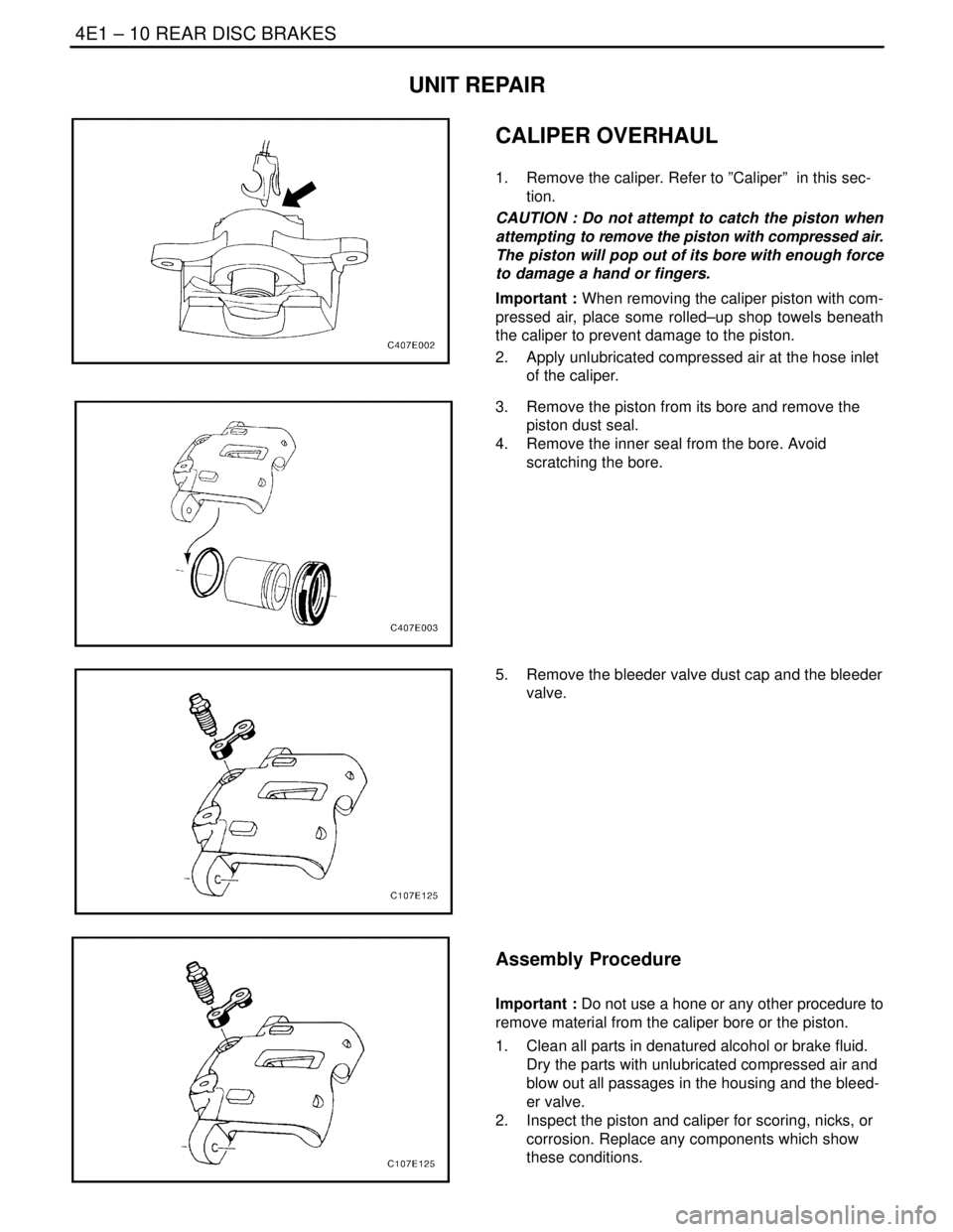
1. Remove the caliper. Refer to ”Caliper” in this sec-
tion.
CAUTION : Do not attempt to catch the piston when
attempting to remove the piston with compressed air.
The piston will pop out of its bore with enough force
to damage a hand or fingers.
Important : When removing the caliper piston with com-
pressed air, place some rolled–up shop towels beneath
the caliper to prevent damage to the piston.
2. Apply unlubricated compressed air at the hose inlet
of the caliper.
3. Remove the piston from its bore and remove the
piston dust seal.
4. Remove the inner seal from the bore. Avoid
scratching the bore.
5. Remove the bleeder valve dust cap and the bleeder
valve.
Assembly Procedure
Important : Do not use a hone or any other procedure to
remove material from the caliper bore or the piston.
1. Clean all parts in denatured alcohol or brake fluid.
Dry the parts with unlubricated compressed air and
blow out all passages in the housing and the bleed-
er valve.
2. Inspect the piston and caliper for scoring, nicks, or
corrosion. Replace any components which show
these conditions.
Page 1087 of 2643
4F – 6IANTILOCK BRAKE SYSTEM
DAEWOO V–121 BL4
COMPONENT LOCATOR
ABS/EBD SYSTEM DRIVE
(Left–Hand Drive Shown, Right–Hand Drive Similar)
1. Right Front Wheel Speed Sensor
2. Brake Master Cylinder
3. Master Cylinder Reservoir
4. Grommet
5. Right Front Wheel Speed Sensor Connector
6. Brake Fluid Level Switch Connector
7. Instrument Cluster
8. Connector C302
9. Right Rear Wheel Speed Sensor Connector
10. Right Rear Wheel Speed Sensor
11. Left Rear Wheel Speed Sensor12. Left Rear Wheel Speed Sensor Connector
13. Body Wiring Harness
14. Connector C202
15. Connectors C110
16. EBCM Connector
17. Left Front Speed Sensor Connector
18. Grommet
19. Hydraulic Modulator with Attached EBCM
20. Connector C107
21. Left Front Wheel Speed Sensor
Page 1142 of 2643

ANTILOCK BRAKE SYSTEM 4F – 61
DAEWOO V–121 BL4
BLEEDING SYSTEM
Replacement modulators are shipped already filled and
bled. In normal procedures requiring removal of the modu-
lator, such as to replace the EBCM, air will not enter the
modulator, and normal bleeding will be all that is needed.
For this procedure, refer to Section 4A, Hydraulic Brakes.
If air enters the hydraulic modulator, or if an unfilled modu-
lator is installed, use the brake bleeding program in the
scan tool to bleed the modulator. Manual bleeding of the
hydraulic modulator is not possible.
ABS 5.3 ASSEMBLY
(Left–Hand Drive Shown, Right–Hand Drive
Similar)
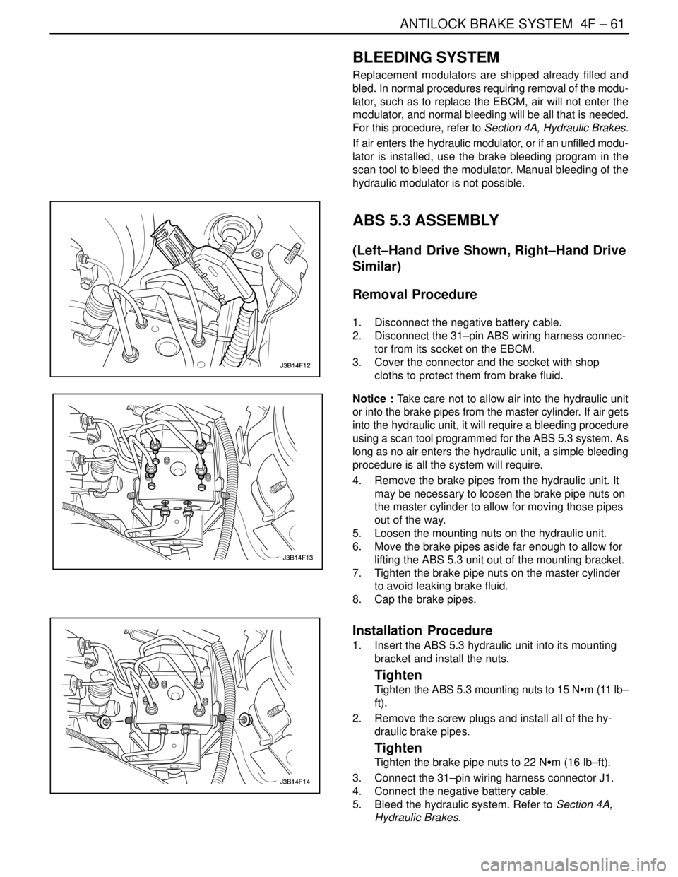
Removal Procedure
1. Disconnect the negative battery cable.
2. Disconnect the 31–pin ABS wiring harness connec-
tor from its socket on the EBCM.
3. Cover the connector and the socket with shop
cloths to protect them from brake fluid.
Notice : Take care not to allow air into the hydraulic unit
or into the brake pipes from the master cylinder. If air gets
into the hydraulic unit, it will require a bleeding procedure
using a scan tool programmed for the ABS 5.3 system. As
long as no air enters the hydraulic unit, a simple bleeding
procedure is all the system will require.
4. Remove the brake pipes from the hydraulic unit. It
may be necessary to loosen the brake pipe nuts on
the master cylinder to allow for moving those pipes
out of the way.
5. Loosen the mounting nuts on the hydraulic unit.
6. Move the brake pipes aside far enough to allow for
lifting the ABS 5.3 unit out of the mounting bracket.
7. Tighten the brake pipe nuts on the master cylinder
to avoid leaking brake fluid.
8. Cap the brake pipes.
Installation Procedure
1. Insert the ABS 5.3 hydraulic unit into its mounting
bracket and install the nuts.
Tighten
Tighten the ABS 5.3 mounting nuts to 15 NSm (11 lb–
ft).
2. Remove the screw plugs and install all of the hy-
draulic brake pipes.
Tighten
Tighten the brake pipe nuts to 22 NSm (16 lb–ft).
3. Connect the 31–pin wiring harness connector J1.
4. Connect the negative battery cable.
5. Bleed the hydraulic system. Refer to Section 4A,
Hydraulic Brakes.
Page 1144 of 2643

ANTILOCK BRAKE SYSTEM 4F – 63
DAEWOO V–121 BL4
FRONT WHEEL SPEED SENSOR
JUMPER HARNESS
(Left–Hand Drive Shown, Right–Hand Drive
Similar)
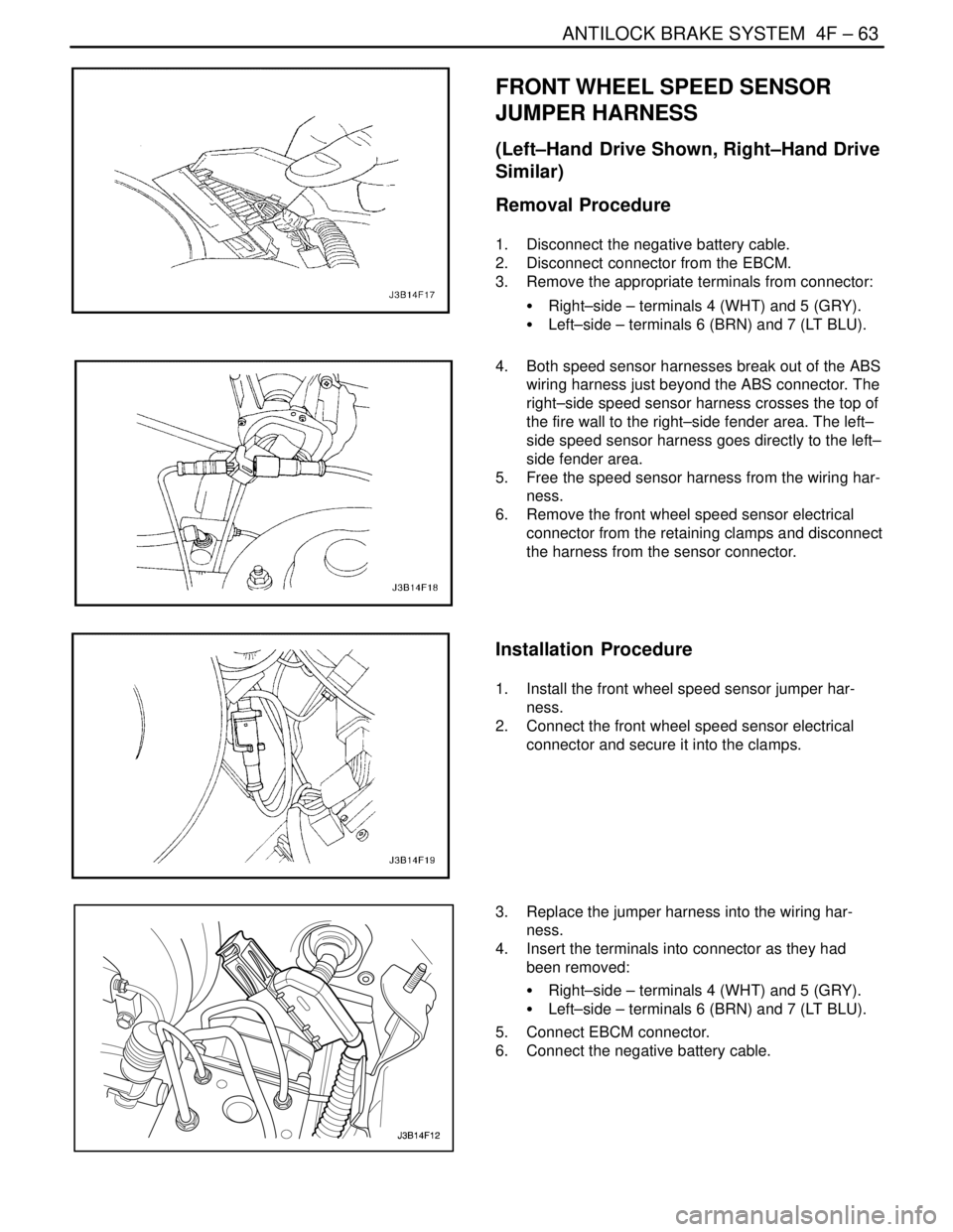
Removal Procedure
1. Disconnect the negative battery cable.
2. Disconnect connector from the EBCM.
3. Remove the appropriate terminals from connector:
S Right–side – terminals 4 (WHT) and 5 (GRY).
S Left–side – terminals 6 (BRN) and 7 (LT BLU).
4. Both speed sensor harnesses break out of the ABS
wiring harness just beyond the ABS connector. The
right–side speed sensor harness crosses the top of
the fire wall to the right–side fender area. The left–
side speed sensor harness goes directly to the left–
side fender area.
5. Free the speed sensor harness from the wiring har-
ness.
6. Remove the front wheel speed sensor electrical
connector from the retaining clamps and disconnect
the harness from the sensor connector.
Installation Procedure
1. Install the front wheel speed sensor jumper har-
ness.
2. Connect the front wheel speed sensor electrical
connector and secure it into the clamps.
3. Replace the jumper harness into the wiring har-
ness.
4. Insert the terminals into connector as they had
been removed:
S Right–side – terminals 4 (WHT) and 5 (GRY).
S Left–side – terminals 6 (BRN) and 7 (LT BLU).
5. Connect EBCM connector.
6. Connect the negative battery cable.
Page 1153 of 2643

SECTION : 4G
PARKING BRAKE
TABLE OF CONTENTS
SPECIFICATIONS4G–1 . . . . . . . . . . . . . . . . . . . . . . . . . .
Fastener Tightening Specifications 4G–1. . . . . . . . . .
MAINTENANCE AND REPAIR4G–2 . . . . . . . . . . . . . . .
ON–VEHICLE SERVICE 4G–2. . . . . . . . . . . . . . . . . . . . .
Parking Brake Adjustment Rear Drum Brakes 4G–2.
Parking Brake Adjustment Rear Disc Brakes 4G–2. . Parking Brake Lever 4G–3. . . . . . . . . . . . . . . . . . . . . . .
Parking Brake Cable 4G–5. . . . . . . . . . . . . . . . . . . . . . .
Parking Brake Handle 4G–8. . . . . . . . . . . . . . . . . . . . . .
GENERAL DESCRIPTION AND SYSTEM
OPERATION4G–9 . . . . . . . . . . . . . . . . . . . . . . . . . . . . . .
Parking Brake 4G–9. . . . . . . . . . . . . . . . . . . . . . . . . . . .
SPECIFICATIONS
FASTENER TIGHTENING SPECIFICATIONS
ApplicationNSmLb–FtLb–In
Parking Brake Cable–to–Underbody Side
Bracket bolts6–53
Parking Brake Lever Assembly–to–Vehicle
Underbody Bolts2216–
Parking Brake Switch–to–Parking Brake Le-
ver Screw4–35
Rear Brake Drum Detent Screw4–35