2004 DAEWOO LACETTI water pump
[x] Cancel search: water pumpPage 197 of 2643
1D – 2IENGINE COOLING
DAEWOO V–121 BL4
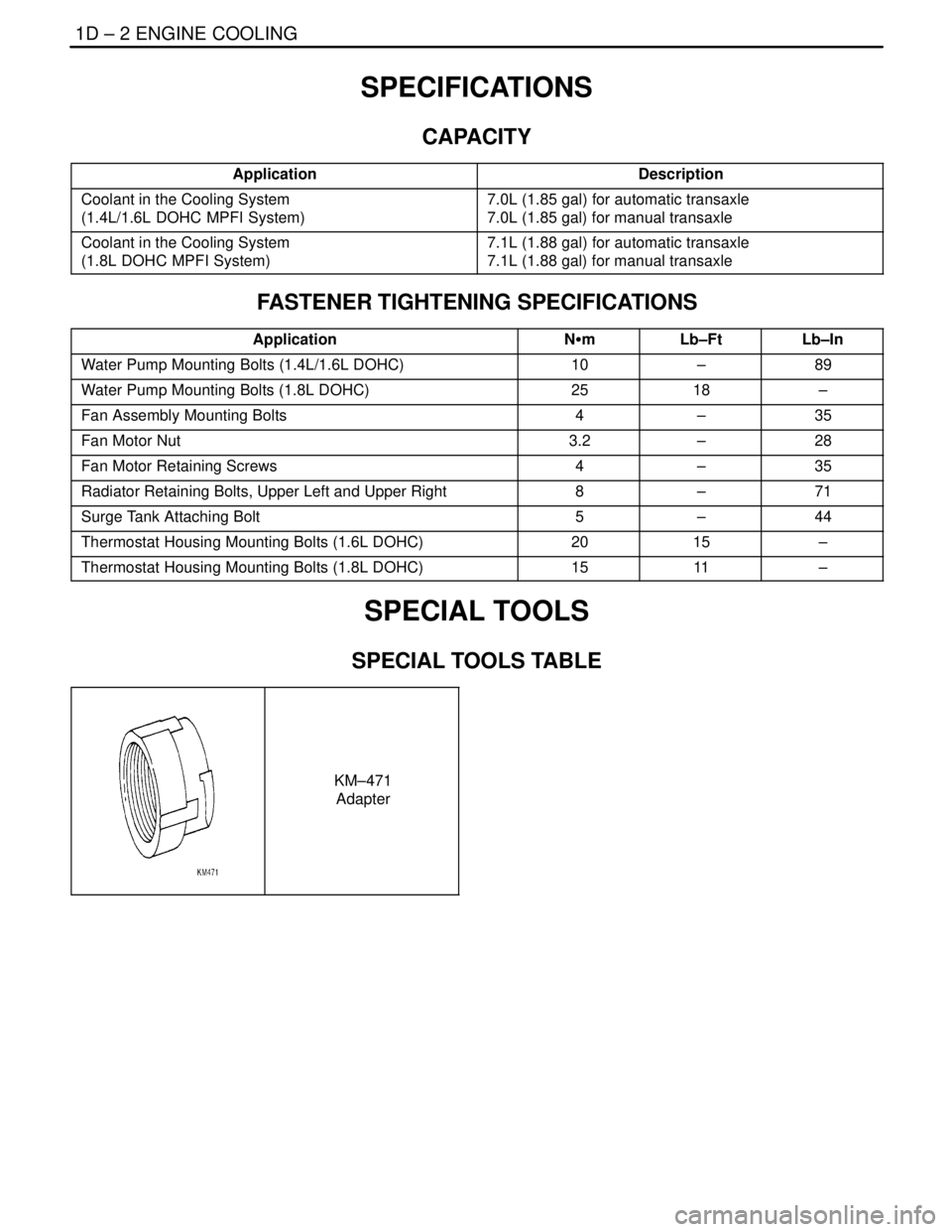
SPECIFICATIONS
CAPACITY
ApplicationDescription
Coolant in the Cooling System
(1.4L/1.6L DOHC MPFI System)7.0L (1.85 gal) for automatic transaxle
7.0L (1.85 gal) for manual transaxle
Coolant in the Cooling System
(1.8L DOHC MPFI System)7.1L (1.88 gal) for automatic transaxle
7.1L (1.88 gal) for manual transaxle
FASTENER TIGHTENING SPECIFICATIONS
ApplicationNSmLb–FtLb–In
Water Pump Mounting Bolts (1.4L/1.6L DOHC)10–89
Water Pump Mounting Bolts (1.8L DOHC)2518–
Fan Assembly Mounting Bolts4–35
Fan Motor Nut3.2–28
Fan Motor Retaining Screws4–35
Radiator Retaining Bolts, Upper Left and Upper Right8–71
Surge Tank Attaching Bolt5–44
Thermostat Housing Mounting Bolts (1.6L DOHC)2015–
Thermostat Housing Mounting Bolts (1.8L DOHC)1511–
SPECIAL TOOLS
SPECIAL TOOLS TABLE
KM–471
Adapter
Page 199 of 2643

1D – 4IENGINE COOLING
DAEWOO V–121 BL4
COOLING SYSTEM DIAGNOSIS
Engine Overheats
ChecksAction
Check for a loss of the coolant.Add the coolant.
Check for a weak coolant solution.Confirm that the coolant solution is a 50/50 mixture of eth-
ylene glycol and water.
Check the front of the radiator for any dirt, any leaves, or
any insects.Clean the front of the radiator.
Check for leakage from the hoses, the coolant pump, the
heater, the thermostat housing, the radiator, the core
plugs, or the head gasket.Replace any damaged components.
Check for a faulty thermostat.Replace a damaged thermostat.
Check for retarded ignition timing.Perform an ECM code diagnosis. Confirm the integrity of
the timing belt.
Check for an improperly operating electric cooling fan.Replace the electric cooling fan.
Check for radiator hoses that are plugged or rotted.Replace any damaged radiator hoses.
Check for a faulty water pump.Replace a faulty water pump.
Check for a faulty surge tank cap.Replace a faulty surge tank cap.
Check for a cylinder head or an engine block that is
cracked or plugged.Repair the damaged cylinder head or the damaged engine
block.
Loss of Coolant
ChecksAction
Check for a leak in the radiator.Replace a damaged radiator.
Check for a leak in the following locations:
S Surge tank.
S Hose.Replace the following parts, as needed:
S Surge tank.
S Hose.
Check for loose or damaged radiator hoses, heater hoses,
and connections.Reseat the hoses.
Replace the hoses or the clamps.
Check for leaks in the coolant pump seal.Replace the coolant pump seal.
Check for leaks in the coolant pump gasket.Replace the coolant pump gasket.
Check for an improper cylinder head torque.Tighten the cylinder head bolts to specifications.
Replace the cylinder head gasket, if needed.
Check for leaks in the following locations:
S Intake manifold.
S Cylinder head gasket.
S Cylinder block plug.
S Heater core.
S Radiator drain plug.Repair or replace any components, as needed, to correct
the leak.
Engine Fails to Reach Normal Operating Temperature or Cool Air
from the Heater
ChecksAction
Check to determine if the thermostat is stuck open or is the
wrong type of thermostat.Install a new thermostat of the correct type and heat range.
Check the coolant level to determine if it is below the MIN
mark on the surge tank.Add sufficient coolant to raise the fluid to the specified
mark on the surge tank.
Page 201 of 2643
1D – 6IENGINE COOLING
DAEWOO V–121 BL4
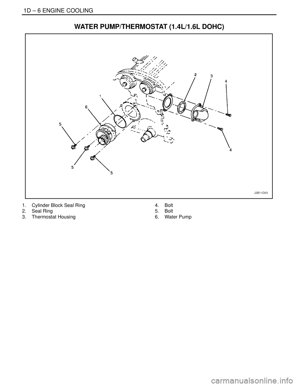
WATER PUMP/THERMOSTAT (1.4L/1.6L DOHC)
1. Cylinder Block Seal Ring
2. Seal Ring
3. Thermostat Housing4. Bolt
5. Bolt
6. Water Pump
Page 202 of 2643
ENGINE COOLING 1D – 7
DAEWOO V–121 BL4
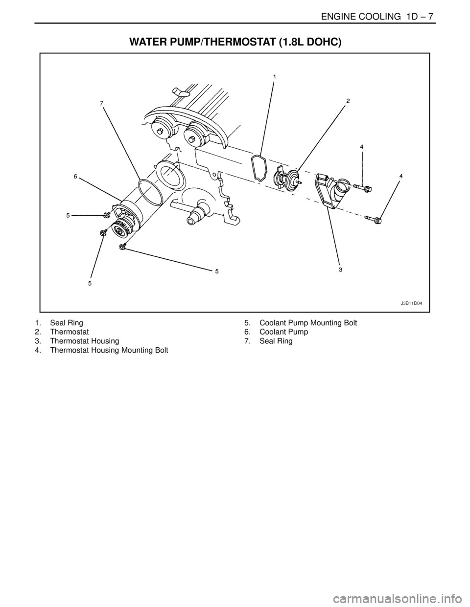
WATER PUMP/THERMOSTAT (1.8L DOHC)
1. Seal Ring
2. Thermostat
3. Thermostat Housing
4. Thermostat Housing Mounting Bolt5. Coolant Pump Mounting Bolt
6. Coolant Pump
7. Seal Ring
Page 206 of 2643
ENGINE COOLING 1D – 11
DAEWOO V–121 BL4
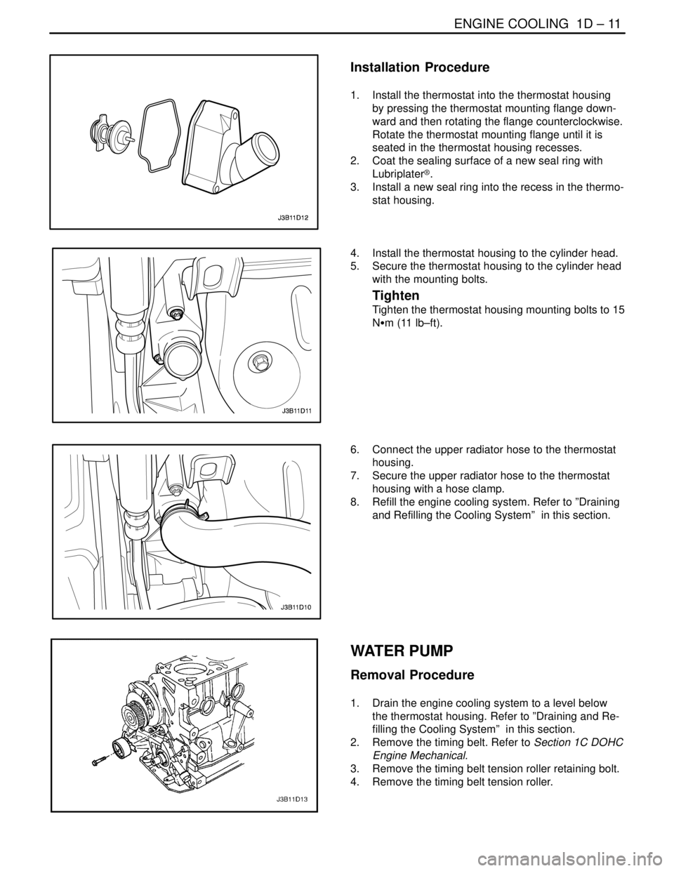
Installation Procedure
1. Install the thermostat into the thermostat housing
by pressing the thermostat mounting flange down-
ward and then rotating the flange counterclockwise.
Rotate the thermostat mounting flange until it is
seated in the thermostat housing recesses.
2. Coat the sealing surface of a new seal ring with
Lubriplater®.
3. Install a new seal ring into the recess in the thermo-
stat housing.
4. Install the thermostat housing to the cylinder head.
5. Secure the thermostat housing to the cylinder head
with the mounting bolts.
Tighten
Tighten the thermostat housing mounting bolts to 15
NSm (11 lb–ft).
6. Connect the upper radiator hose to the thermostat
housing.
7. Secure the upper radiator hose to the thermostat
housing with a hose clamp.
8. Refill the engine cooling system. Refer to ”Draining
and Refilling the Cooling System” in this section.
WATER PUMP
Removal Procedure
1. Drain the engine cooling system to a level below
the thermostat housing. Refer to ”Draining and Re-
filling the Cooling System” in this section.
2. Remove the timing belt. Refer to Section 1C DOHC
Engine Mechanical.
3. Remove the timing belt tension roller retaining bolt.
4. Remove the timing belt tension roller.
Page 207 of 2643
1D – 12IENGINE COOLING
DAEWOO V–121 BL4
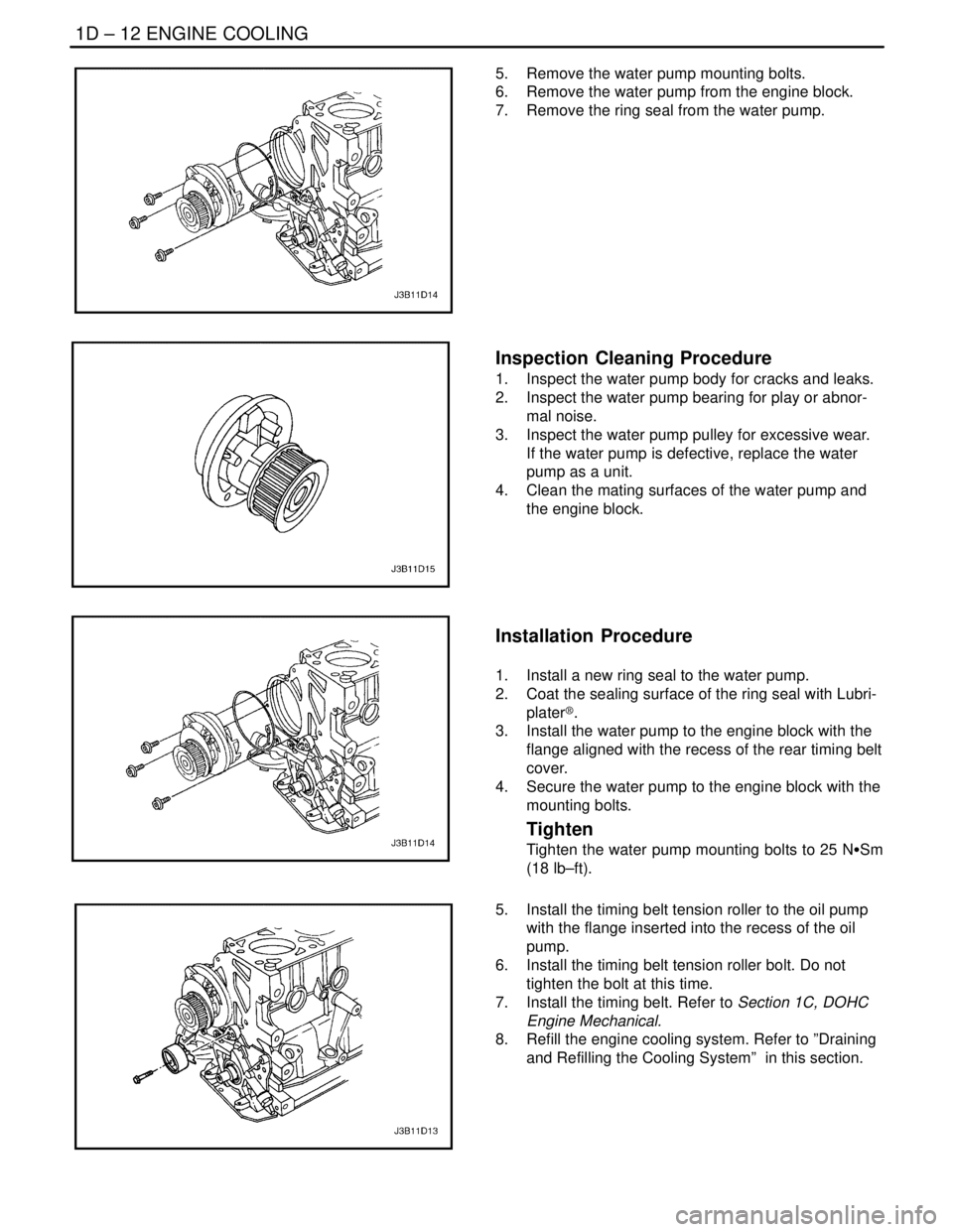
5. Remove the water pump mounting bolts.
6. Remove the water pump from the engine block.
7. Remove the ring seal from the water pump.
Inspection Cleaning Procedure
1. Inspect the water pump body for cracks and leaks.
2. Inspect the water pump bearing for play or abnor-
mal noise.
3. Inspect the water pump pulley for excessive wear.
If the water pump is defective, replace the water
pump as a unit.
4. Clean the mating surfaces of the water pump and
the engine block.
Installation Procedure
1. Install a new ring seal to the water pump.
2. Coat the sealing surface of the ring seal with Lubri-
plater®.
3. Install the water pump to the engine block with the
flange aligned with the recess of the rear timing belt
cover.
4. Secure the water pump to the engine block with the
mounting bolts.
Tighten
Tighten the water pump mounting bolts to 25 NSSm
(18 lb–ft).
5. Install the timing belt tension roller to the oil pump
with the flange inserted into the recess of the oil
pump.
6. Install the timing belt tension roller bolt. Do not
tighten the bolt at this time.
7. Install the timing belt. Refer to Section 1C, DOHC
Engine Mechanical.
8. Refill the engine cooling system. Refer to ”Draining
and Refilling the Cooling System” in this section.
Page 213 of 2643

1D – 18IENGINE COOLING
DAEWOO V–121 BL4
GENERAL DESCRIPTION
AND SYSTEM OPERATION
GENERAL DESCRIPTION
The cooling system maintains the engine temperature at
an efficient level during all engine operating conditions.
When the engine is cold, the cooling system cools the en-
gine slowly or not at all. This slow cooling of the engine al-
lows the engine to warm up quickly.
The cooling system includes a radiator and recovery sub-
system, cooling fans, a thermostat and housing, a coolant
pump, and a coolant pump drive belt. The timing belt
drives the coolant pump.
All components must function properly in order for the
cooling system to operate. The coolant pump draws the
coolant from the radiator. The coolant then circulates
through water jackets in the engine block, the intake man-
ifold, and the cylinder head. When the coolant reaches the
operating temperature of the thermostat, the thermostat
opens. The coolant then goes back to the radiator where
it cools.
This system directs some coolant through the hoses to the
heater core. This provides for heating and defrosting. The
surge tank is connected to the radiator to recover the cool-
ant displaced by expansion from the high temperatures.
The surge tank maintains the correct coolant level.
The cooling system for this vehicle has no radiator cap or
filler neck. The coolant is added to the cooling system
through the surge tank.
RADIATOR
This vehicle has a lightweight tube–and–fin aluminum ra-
diator. Plastic tanks are mounted on the right and the left
sides of the radiator core.
On vehicles equipped with automatic transaxles, the
transaxle fluid cooler lines run through the left radiator
tank. A radiator drain cock is on this radiator.
To drain the cooling system, open the drain cock.
SURGE TANK
The surge tank is a transparent plastic reservoir, similar to
the windshield washer reservoir.
The surge tank is connected to the radiator by a hose and
to the engine cooling system by another hose. As the ve-
hicle is driven, the engine coolant heats and expands. The
portion of the engine coolant displaced by this expansion
flows from the radiator and the engine into the surge tank.
The air trapped in the radiator and the engine is degassed
into the surge tank.When the engine stops, the engine coolant cools and con-
tracts. The displaced engine coolant is then drawn back
into the radiator and the engine. This keeps the radiator
filled with the coolant to the desired level at all times and
increases the cooling efficiency.
Maintain the coolant level between the MIN and the MAX
marks on the surge tank when the system is cold.
WATER PUMP
The belt–driven centrifugal water pump consists of an im-
peller, a drive shaft, and a belt pulley. The water pump is
mounted on the front of the transverse–mounted engine,
and is driven by the timing belt.
The impeller is supported by a completely sealed bearing.
The water pump is serviced as an assembly and, there-
fore, cannot be disassembled.
THERMOSTAT
A wax pellet–type thermostat controls the flow of the en-
gine coolant through the engine cooling system. The ther-
mostat is mounted in the thermostat housing to the front
of the cylinder head.
The thermostat stops the flow of the engine coolant from
the engine to the radiator in order to provide faster warm–
up, and to regulate the coolant temperature. The thermo-
stat remains closed while the engine coolant is cold, pre-
venting circulation of the engine coolant through the
radiator. At this point, the engine coolant is allowed to cir-
culate only throughout the heater core to warm it quickly
and evenly.
As the engine warms, the thermostat opens. This allows
the engine coolant to flow through the radiator, where the
heat is dissipated through the radiator. This opening and
closing of the thermostat permits enough engine coolant
to enter the radiator to keep the engine within proper en-
gine temperature operating limits.
The wax pellet in the thermostat is hermetically sealed in
a metal case. The wax element of the thermostat expands
when it is heated and contracts when it is cooled.
As the vehicle is driven and the engine warms, the engine
coolant temperature increases. When the engine coolant
reaches a specified temperature, the wax pellet element
in the thermostat expands and exerts pressure against the
metal case, forcing the valve open. This allows the engine
coolant to flow through the engine cooling system and cool
the engine.
As the wax pellet cools, the contraction allows a spring to
close the valve.
The thermostat begins to open at 87°C (189°F) and is fully
open at 102°C (216°F). The thermostat closes at 86°C
(187°F).
Page 404 of 2643

1F – 158IENGINE CONTROLS
DAEWOO V–121 BL4
DIAGNOSTIC TROUBLE CODE (DTC) P0171
FUEL TRIM SYSTEM TOO LEAN
System Description
If the adaptation value threshold is permanently exceed-
ed, the deviation of the adaptive terms enables to detect
a slow default coming out. Two time counters (one for the
rich side and another one for the lean side) are increased
while the lambda controller exceeds the adaptation
thresholds. As soon as one of the time counters reaches
its maximum value, the error is detected.
The aim of this test is to simulate a failure that would result
in exceeding the adaptive terms. Two kinds of failure must
be created.
S A lean side deviation: P0171
S A rich side deviation : P0172
It is thus necessary to determine, for each kind of failure,
the limit good and the limit bad. For a given failure, mea-
sure the emission threshold until the legal emission
thresholds are exceeded.
Note that the problem is due to the emission thresholds re-
quired, it is not simple to disturb the system so that the
emission thresholds will be exceeded. The tuning has
been made thanks to a dedicated calibration but, as such
a procedure is not permitted by the regulation, it is neces-
sary to create some material malfunction (fuel pressure
regulator, fuel injector, air leakage...).
Conditions for Setting the DTC
S DTCs P0107, P0108, P0112, P0113, P0117,
P0118, P0122, P0123, P0131, P0132, P0337,
P0338, P0341, P0342, P0400, P1319, P1402,
P1404, P1405, P1671 and P1672 are not set.
S Coolant temperature is greater than 20°C (68°F).
(1.4L DOHC)
S Coolant temperature is greater than 80°C (176°F).
(1.6L DOHC)
S Manifold Absolute Pressure (MAP) is greater than
70 kPa (10.2 psi).
S System is in closed loop.
Action Taken When the DTC Sets
S The Malfunction Indicator Lamp (MIL) will illuminate
after three consecutive trip with a fail.
S The ECM will record operating conditions at the
time the diagnostic fail. This information will be
stored in the Freeze Frame and Failure Records
buffers.S A history DTC is stored.
Conditions for Clearing the MIL/DTC
S The MIL will turn off after four consecutive ignition
cycles in which the diagnostic runs without a fault.
S A history DTC will clear after 40 consecutive warm
up cycles without a fault.
S DTC(s) can be cleared by using the scan tool.
S Disconnecting the ECM battery feed for 10 sec-
onds.
Diagnostic Aids
Important : After repairs, use the scan tool Fuel Trim Re-
set function to reset the long–term fuel trim to 128 (0%).
S Fuel pressure – The system will be lean if the pres-
sure is too low. It may be necessary to monitor fuel
pressure while driving the vehicle at various road
speeds and/or loads to confirm.
S Map sensor – An output that causes the ECM to
sense a lower than normal manifold pressure (high
vacuum) can cause the system to go lean. Discon-
necting the MAP sensor will allow the ECM to sub-
stitute a fixed (default) value for the MAP sensor. If
the lean condition is gone when the sensor is dis-
connected, substitute a known good sensor and
recheck.
S Fuel contamination – Water, in even small amounts,
near the in–tank fuel pump inlet can be delivered to
the injector. The water causes a lean exhaust and
can set DTC P0171.
Check for poor O2S or MAP sensor connection at the
ECM. Inspect the harness connectors for the following
conditions:
S Backed–out terminals
S Improper mating
S Broken locks
S Improperly formed
S Damaged terminals
S Poor terminal–to–wire connection
Inspect the wiring harness for damage. If the harness ap-
pears to be OK, observe the O2S display on the scan tool
while moving the connectors and the wiring harness re-
lated to the engine harness. A change in the display will
indicate the location of the fault.
Check the brake power booster check valve for possible
leaks.