Page 1559 of 2643
5A1 – 210IZF 4 HP 16 AUTOMATIC TRANSAXLE
DAEWOO V–121 BL4
4. Install the rear transaxle mounting bracket bolts (a).
Tighten
Tighten the rear transaxle mounting bracket bolts (a)
to 62 NSm (45 lb–ft).
5. Install the damping block connection bolt and nut
(b).
Tighten
Tighten the damping block connection bolt and nut (b)
to 68 NSm (50 lb–ft).
6. Install the torque converter bolts.
7. Install the starter motor. Refer to Section 1E, En-
gine Electrical.
8. Install the drive axle. Refer to Section 3A, Automat-
ic Drive Axle.
9. Install the oil cooler pipes from the transaxle. Refer
to ”Oil Cooler Pipes/Hoses” in this section.
10. Lower the vehicle.
11. Install the left transaxle mounting bracket. Refer to
”Left Transaxle Mounting Bracket” in this section.
Page 1561 of 2643

5A1 – 212IZF 4 HP 16 AUTOMATIC TRANSAXLE
DAEWOO V–121 BL4
UNIT REPAIR
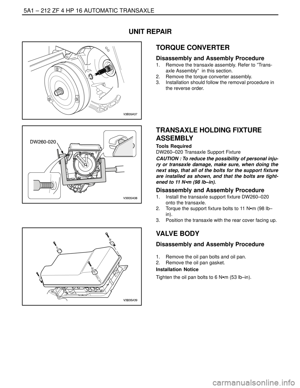
TORQUE CONVERTER
Disassembly and Assembly Procedure
1. Remove the transaxle assembly. Refer to ”Trans-
axle Assembly” in this section.
2. Remove the torque converter assembly.
3. Installation should follow the removal procedure in
the reverse order.
TRANSAXLE HOLDING FIXTURE
ASSEMBLY
Tools Required
DW260–020 Transaxle Support Fixture
CAUTION : To reduce the possibility of personal inju-
ry or transaxle damage, make sure, when doing the
next step, that all of the bolts for the support fixture
are installed as shown, and that the bolts are tight-
ened to 11 NSm (98 lb–in).
Disassembly and Assembly Procedure
1. Install the transaxle support fixture DW260–020
onto the transaxle.
2. Torque the support fixture bolts to 11 NSm (98 lb–
in).
3. Position the transaxle with the rear cover facing up.
VALVE BODY
Disassembly and Assembly Procedure
1. Remove the oil pan bolts and oil pan.
2. Remove the oil pan gasket.
Installation Notice
Tighten the oil pan bolts to 6 NSm (53 lb–in).
Page 1576 of 2643

ZF 4 HP 16 AUTOMATIC TRANSAXLE 5A1 – 227
DAEWOO V–121 BL4
2. Find the disc set’s thickness. Refer to the below
table.
PF
Disc set’s Thickness
3.01~3.19mm1.8mm
3.20~3.48mm2.1mm
3.49~3.88mm2.5mm
3.89~4.08mm2.7mm
4.09~4.30mm3.0mm
PE is 4.20mm so, the disc set’s thickness is
3.0mm.
3. Replace clutch B’s setting disc. (3.0mm)
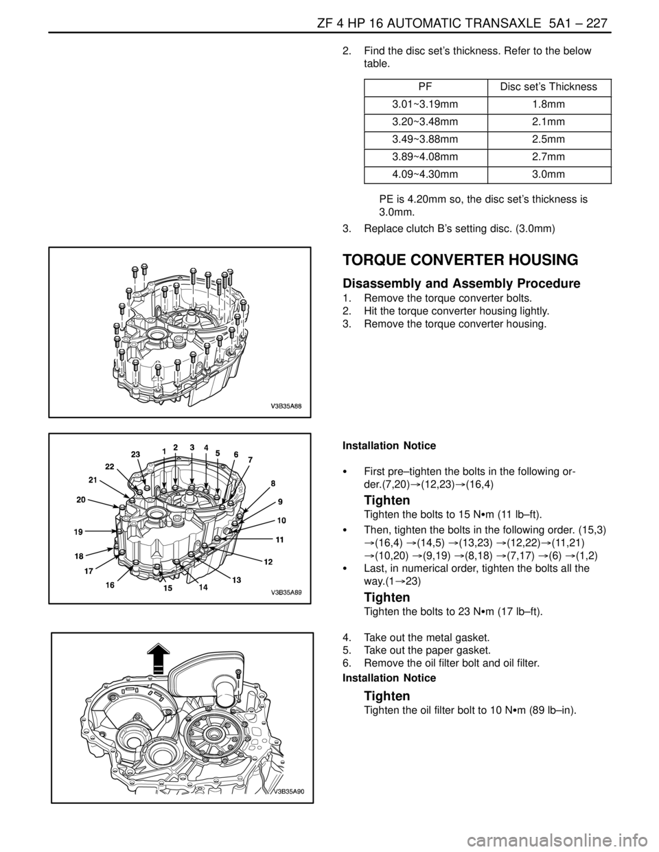
TORQUE CONVERTER HOUSING
Disassembly and Assembly Procedure
1. Remove the torque converter bolts.
2. Hit the torque converter housing lightly.
3. Remove the torque converter housing.
Installation Notice
S First pre–tighten the bolts in the following or-
der.(7,20)�(12,23)�(16,4)
Tighten
Tighten the bolts to 15 NSm (11 lb–ft).
S Then, tighten the bolts in the following order. (15,3)
�(16,4) �(14,5) �(13,23) �(12,22)�(11,21)
�(10,20) �(9,19) �(8,18) �(7,17) �(6) �(1,2)
S Last, in numerical order, tighten the bolts all the
way.(1�23)
Tighten
Tighten the bolts to 23 NSm (17 lb–ft).
4. Take out the metal gasket.
5. Take out the paper gasket.
6. Remove the oil filter bolt and oil filter.
Installation Notice
Tighten
Tighten the oil filter bolt to 10 NSm (89 lb–in).
Page 1594 of 2643

5A2 – 4IAISIN AUTOMATIC TRANSAXLE
DAEWOO V–121 BL4
FASTENER TIGHTENING SPECIFICATIONS
ApplicationNSmLb–FtLb–In
Drain Plug1713–
Control Cable Adjusting Nut8–71
Shift Control Lever Assembly Mounting Bolts8–71
Manual Valve Lever Shaft Nut12–106
Transmission Range (TR) Switch Bolts5.4–48
Input Speed Sensor Retaining Bolt5.4–48
Output Speed Sensor Retaining Bolt7.4–65
TCM Retaining Bolts5–44
Fluid Cooler Inlet Pipe Fitting Nut3526–
Fluid Cooler Inlet Pipe Bolt9–80
Inlet Pipe Union Bolt3526–
Fluid Cooler Rear Outlet Pipe Fitting Nut3526–
Fluid Cooler Rear Outlet Pipe Clip Bolt9–80
Front Outlet Pipe Union Bolt3526–
Lower Transaxle–to–Engine Retaining Bolts (a)7354–
Lower Transaxle–to–Engine Retaining Bolts (b)3123–
Lower Transaxle–to–Engine Retaining Bolts (c)2115–
Upper Transaxle–to–Engine Mounting Bolts7354–
Upper Transaxle Mounting Bracket Bolts6044–
Rear Mounting Bracket Bolts6044–
Damping Block Connection Nut and Bolt8059–
Torque Converter Bolts4543–
Screw Plugs7.4–65
Transaxle Apply Clamp Bolt5.4–48
Oil Reservoir Lock Plate Bolts5.4–48
Transaxle Case Plate Bolt9.8–87
Transaxle Housing Bolts2922–
Manual Detent Spring Bolt9.8–87
Parking Lock Pawl Bracket Bolts7.4–65
Planetary Ring Gear Nut (Standard)9.8–87
Planetary Ring Gear Nut (Maximum)2922–
Transaxle Rear Cover Bolts2518–
Oil Pump Bolts2518–
Valve Body Bolts11–97
Oil Strainer Bolts9.8–87
Oil Pan Bolts7–62
Unions2518–
Stator Shaft Bolts2518–
Shift Solenoid Valve Bolts11–97
Differential Case–to–Differential Ring Gear Bolt10275–
Page 1620 of 2643

5A2 – 30IAISIN AUTOMATIC TRANSAXLE
DAEWOO V–121 BL4
Manual Shifting Test
Manual shifting test is to determine whether failure symp-
tom is within electrical failure or mechanical failure.
1. Disconnect wire harness of shift solenoid, check
the range and gear positions correspond with below
table when driving by manual shifting.
Range
Gear
D3rd gear
RReverse
Notice : Make sure to disconnect only wire harness of shift
solenoid.
UNIT INSPECTION
Drive Plate Deflection
S Inspect drive plate deflection if within standard
value.
Standard Value
within 0.2mm (0.008 in)
Action :
Standard value is not within the specified value, replace
drive plate.
When ”abnormal wear” or ”stick” on torque converter
sleeve or oil pump is found, replace torque converter and
A/T.
Notice :
S When assembling torque converter and drive plate.
Be sure to use correct bolt with correct length. The
bolt pushes up torque converter front cover, and it
damages lock–up clutch lining. As a result, it cause
major failure ”No move”.
S Do not tighten the bolts by using impact wrench.
Cooler Pipe Bending and Choke
S Inspect it whether there is abnormal pipe bending in
the cooler pipe, pipe deformation and small cross–
section area of pipe line.
Action : Replace failure parts.S Apply compressed air of 2kg/cm
2 from cooler pipe
inlet side, inspect whether there is not cooler pipe
choke by confirming air flow smooth.
Action : Remove foreign particles and clean inside of pipe
line.
Normal
Vehicle Speed Sensor
1. Remove the connector of vehicle speed sensor,
connect 12V power supply and voltmeter to the ter-
minal.(Do not mistake polarity)
2. Check voltage change from approx. 0V to 12V with
vehicle speed sensor driven gear rotated.
Notice : The voltage change should be 4 times for 1 revo-
lution of the vehicle speed sensor driven gear.
Action : If the result of inspection is bad, replace the ve-
hicle speed sensor.
Page 1702 of 2643
5A2 – 112IAISIN AUTOMATIC TRANSAXLE
DAEWOO V–121 BL4
7. Disconnect the input shaft speed (ISS) sensor elec-
trical connector.
8. Disconnect the output shaft speed (OSS) sensor
electrical connector.
9. Disconnect the Transmission Range (TR) Switch
electrical connector.
10. Disconnect the transaxle electrical connector.
11. Remove the service hall cover.
12. Remove the three torque converter bolts.
13. Remove the damping block connection nut and
bolt.
14. Remove the rear mounting bracket bolts and rear
mounting bracket.
15. Remove the three upper transaxle mounting brack-
et bolts.
Page 1705 of 2643
AISIN AUTOMATIC TRANSAXLE 5A2 – 115
DAEWOO V–121 BL4
5. Install the rear mounting bracket bolts and the
bracket.
Tighten
Tighten the rear mounting bracket bolts to 60 NSm (44
Ib–ft).
6. Install the damping block connection nut and bolt.
Tighten
Tighten the damping block connection nut and bolt to
80 NSm (59 Ib–ft).
7. Install the torque converter bolts.
Tighten
Tighten the torque converter bolts to 45 NSm (33 Ib–
ft).
8. Install the service hall cover.
9. Connect the transaxle electrical connector.
10. Connect the TR switch electrical connector.
11. Connect the OSS sensor electrical connector.
12. Connect the ISS sensor electrical connector.
13. Remove engine support fixture DW110–060.
14. Connect the shift control cable into the transaxle.
Refer to ”Shift Control Cable” in this section.
Page:
< prev 1-8 9-16 17-24